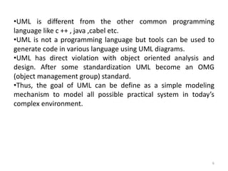
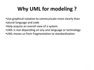
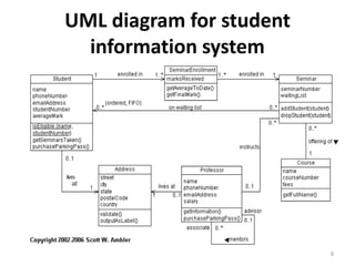
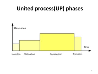
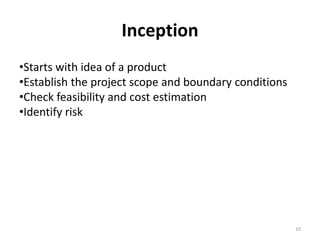
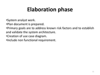
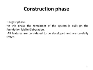
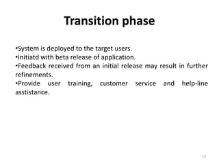
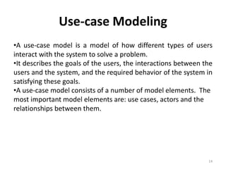
The document provides an introduction to Object-Oriented Analysis and Design (OOAD), emphasizing the importance of classes, objects, encapsulation, abstraction, and polymorphism. It explains the Unified Modeling Language (UML) as a standard mechanism for modeling software systems through diagrams, which facilitates communication and standardization. Additionally, it outlines the phases of the Unified Process, including inception, elaboration, construction, and transition, as well as the concept of use-case modeling to illustrate user interactions with systems.

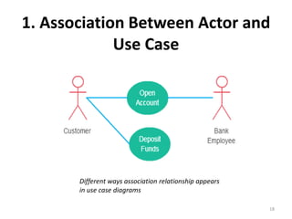
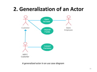
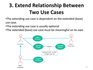


![[RPL2] Pertemuan 3 - UML dan USECASE VIEW](https://cdn.slidesharecdn.com/ss_thumbnails/rpl2pertemuan3-umldanusecaseview-181013010605-thumbnail.jpg?width=640&height=640&fit=bounds)


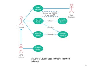
![5G Explained! A High Level Overview [Introduction]](https://cdn.slidesharecdn.com/ss_thumbnails/5gexplainedahighleveloverview-260119165306-cc137a3e-thumbnail.jpg?width=640&height=640&fit=bounds)


