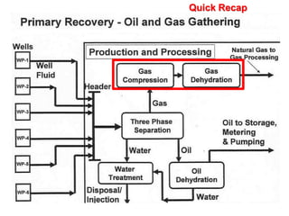
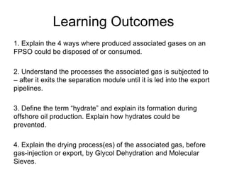
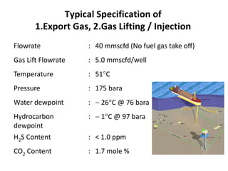
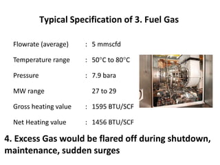
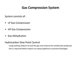
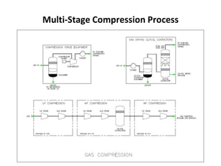
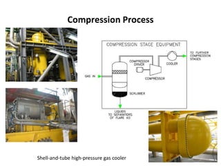
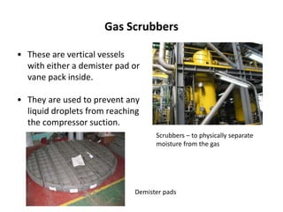
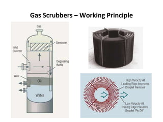
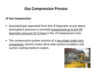
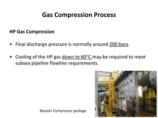
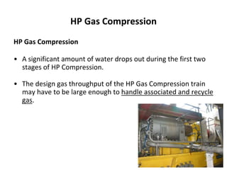
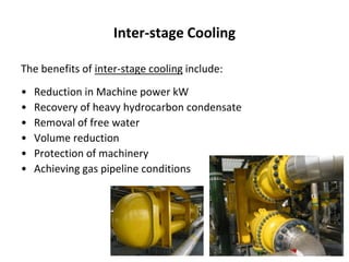
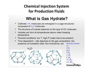
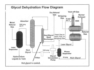
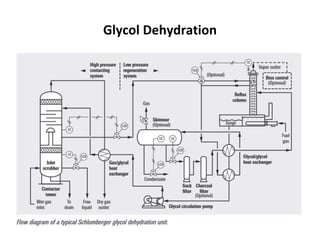
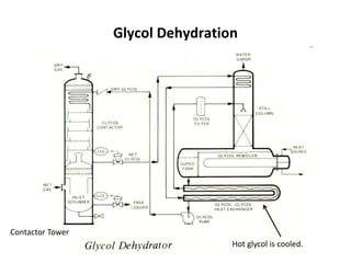
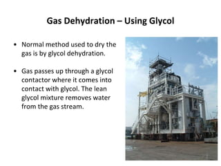
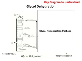
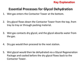
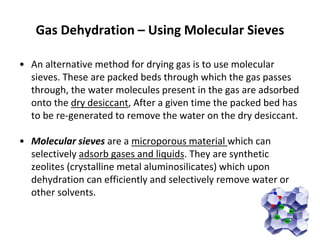
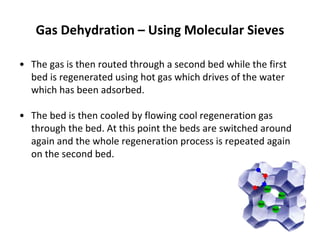
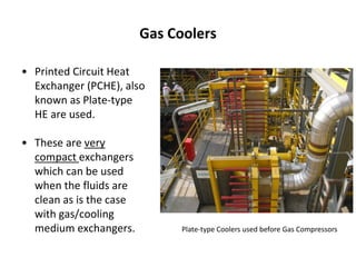
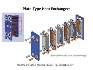
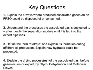
Offshore Production Technology
Gas Compression Systems
Marine & Offshore Technology
Primary Recovery
Quick Recap
Learning Outcomes
1. Explain the 4 ways where produced associated gases on an
FPSO could be disposed of or consumed.
2. Understand the processes the associated gas is subjected to
– after it exits the separation module until it is led into the export
pipelines.
3. Define the term “hydrate” and explain its formation during
offshore oil production. Explain how hydrates could be
prevented.
4. Explain the drying process(es) of the associated gas, before
gas-injection or export, by Glycol Dehydration and Molecular
Sieves.
1. Explain the 4 ways where produced
associated gases on an FPSO could be
disposed of or consumed.
Typical Specification of
1.Export Gas, 2.Gas Lifting / Injection
Flowrate : 40 mmscfd (No fuel gas take off)
Gas Lift Flowrate : 5.0 mmscfd/well
Temperature : 51C
Pressure : 175 bara
Water dewpoint :  26C @ 76 bara
Hydrocarbon
dewpoint
:  1C @ 97 bara
H2S Content : < 1.0 ppm
CO2 Content : 1.7 mole %
Typical Specification of 3. Fuel Gas
Flowrate (average) : 5 mmscfd
Temperature range : 50C to 80C
Pressure : 7.9 bara
MW range 27 to 29
Gross heating value : 1595 BTU/SCF
Net Heating value : 1456 BTU/SCF
4. Excess Gas would be flared off during shutdown,
maintenance, sudden surges
2. Understand the processes the associated
gas is subjected to – after it exits the
separation module until it is led into the
export pipelines.
Gas Compression System
System consists of:
• LP Gas Compression
• HP Gas Compression
• Gas Dehydration
Hydrocarbon Dew Point Control
- using cooling medium to cool the gas and remove the condensate produced
- this is required before export via subsea pipelines to prevent blockages
Principal Equipment of Gas System
LP Gas Compressor (2-stage) 1 × 100%
HP Gas Compressor (3-stage) 1 × 100%
Gas Dehydration Package 1 × 100%
Gas Scrubbers 5 × 100%
Gas Coolers 5 × 100%
Multi-Stage Compression Process
Compression Process
Shell-and-tube high-pressure gas cooler
Gas Scrubbers
• These are vertical vessels
with either a demister pad or
vane pack inside.
• They are used to prevent any
liquid droplets from reaching
the compressor suction.
Scrubbers – to physically separate
moisture from the gas
Demister pads
Gas Scrubbers – Working Principle
Gas Compression Process
LP Gas Compression
• Associated gas separated from the LP Separator at just above
atmospheric pressure is normally compressed up to the HP
Separator pressure of 11 bara in the LP Compression train.
• This compression system consists of a two-stage single train
compressor, electric motor drive with suction scrubbers and
suction cooling medium coolers.
Gas Compression Process
HP Gas Compression
• Gas from the HP Separator, together with gas from the LP
Compressor, will normally flow to the HP Gas Compression
system.
• This system consists of a three-stage single train compressor
electric drive with suction scrubbers and suction cooling
medium coolers.
Gas Compression Process
HP Gas Compression
• Final discharge pressure is normally around 200 bara.
• Cooling of the HP gas down to 60C may be required to meet
subsea pipeline flowline requirements.
Booster Compressor package
Gas Compressors
• Normally these machines are
centrifugal split casing machines
on a common drive, one for the
LP and one for HP machine. The
driver can be either an electric
motor or a gas turbine.
• Reciprocating compressors are
also some times used. This is
very much dependant on the
amount of gas to be
compressed and the final
discharge pressure required.
Gas Compressors
Reciprocating Gas Compressor Package
Gas Compressors
Reciprocating Gas CompressorCentrifugal Gas Compressor
Intermediate Gas Dehydration
HP Gas Compression
• In between the second- and third-stage of compression the
gas may be routed to the dehydration package for final water
removal.
• The location of the dehydration package between the second
and third stages of HP Compression and not on the suction
side of the HP Compression train will reduce the water
removal load on the dehydration package.
HP Gas Compression
HP Gas Compression
• A significant amount of water drops out during the first two
stages of HP Compression.
• The design gas throughput of the HP Gas Compression train
may have to be large enough to handle associated and recycle
gas.
Inter-stage Cooling
The benefits of inter-stage cooling include:
• Reduction in Machine power kW
• Recovery of heavy hydrocarbon condensate
• Removal of free water
• Volume reduction
• Protection of machinery
• Achieving gas pipeline conditions
3. Define the term “hydrate” and explain its
formation during offshore oil production.
Explain how hydrates could be prevented.
Chemical Injection System
for Production Fluids
Chemical Injection System
for Production Fluids
Chemical Injection System
for Production Fluids
Gas Dehydration
• A gas dehydration package is
normally provided to dry the
associated gas prior to gas injection
or gas lift.
• The density of the gas after gas
dehydration is normally around (2
lb/MMSCF).
• This level of dehydration will remove
any risk of hydrate formation when
the gas is used for gas lift purposes.
Gas Dehydration
4. Explain the drying process(es) of the
associated gas, before gas-injection or
export, by Glycol Dehydration and Molecular
Sieves.
Glycol Dehydration
Hot glycol is cooled.
Glycol Dehydration
Glycol Dehydration
Hot glycol is cooled.
Contactor Tower
Gas Dehydration – Using Glycol
• Normal method used to dry the
gas is by glycol dehydration.
• Gas passes up through a glycol
contactor where it comes into
contact with glycol. The lean
glycol mixture removes water
from the gas stream.
Gas Dehydration – Using Glycol
• The glycol is then pumped to a
regeneration package where
the water in the rich glycol
stream is removed to produce
a lean glycol stream again.
• This lean glycol is then pumped
back to dry the incoming gas
stream.
Glycol Dehydration
Glycol Regeneration Package
Key Diagram to understand
Contactor Tower
Essential Processes for Glycol Dehydration
1. Wet gas enters the Contactor Tower at the bottom.
2. Dry glycol flows down the Contactor Tower from the top, from
tray to tray or through packing material.
3. Wet gas contacts dry glycol, and the glycol absorbs water from
the gas.
4. Dry gas would then proceed to the next station.
5. Wet glycol would then be dehydrated via a Glycol Regeneration
Package and cooled before the dry glycol flows back to the
Contactor Tower.
Key Explanation
Gas Dehydration – Using Molecular Sieves
• An alternative method for drying gas is to use molecular
sieves. These are packed beds through which the gas passes
through, the water molecules present in the gas are adsorbed
onto the dry desiccant, After a given time the packed bed has
to be re-generated to remove the water on the dry desiccant.
• Molecular sieves are a microporous material which can
selectively adsorb gases and liquids. They are synthetic
zeolites (crystalline metal aluminosilicates) which upon
dehydration can efficiently and selectively remove water or
other solvents.
Gas Dehydration – Using Molecular Sieves
• The gas is then routed through a second bed while the first
bed is regenerated using hot gas which drives of the water
which has been adsorbed.
• The bed is then cooled by flowing cool regeneration gas
through the bed. At this point the beds are switched around
again and the whole regeneration process is repeated again
on the second bed.
Gas Coolers
• Printed Circuit Heat
Exchanger (PCHE), also
known as Plate-type
HE are used.
• These are very
compact exchangers
which can be used
when the fluids are
clean as is the case
with gas/cooling
medium exchangers. Plate-type Coolers used before Gas Compressors
Plate-Type Heat Exchangers
Working principle of Plate-type Cooler – for illustration only
Key Questions
1. Explain the 4 ways where produced associated gases on an
FPSO could be disposed of or consumed.
2. Understand the processes the associated gas is subjected to
– after it exits the separation module until it is led into the
export pipelines.
3. Define the term “hydrate” and explain its formation during
offshore oil production. Explain how hydrates could be
prevented.
4. Explain the drying process(es) of the associated gas, before
gas-injection or export, by Glycol Dehydration and Molecular
Sieves.

C3.2.2. Topside Gas Compression_2020

  • 1.
    Offshore Production Technology GasCompression Systems Marine & Offshore Technology
  • 2.
  • 3.
    Learning Outcomes 1. Explainthe 4 ways where produced associated gases on an FPSO could be disposed of or consumed. 2. Understand the processes the associated gas is subjected to – after it exits the separation module until it is led into the export pipelines. 3. Define the term “hydrate” and explain its formation during offshore oil production. Explain how hydrates could be prevented. 4. Explain the drying process(es) of the associated gas, before gas-injection or export, by Glycol Dehydration and Molecular Sieves.
  • 4.
    1. Explain the4 ways where produced associated gases on an FPSO could be disposed of or consumed.
  • 5.
    Typical Specification of 1.ExportGas, 2.Gas Lifting / Injection Flowrate : 40 mmscfd (No fuel gas take off) Gas Lift Flowrate : 5.0 mmscfd/well Temperature : 51C Pressure : 175 bara Water dewpoint :  26C @ 76 bara Hydrocarbon dewpoint :  1C @ 97 bara H2S Content : < 1.0 ppm CO2 Content : 1.7 mole %
  • 6.
    Typical Specification of3. Fuel Gas Flowrate (average) : 5 mmscfd Temperature range : 50C to 80C Pressure : 7.9 bara MW range 27 to 29 Gross heating value : 1595 BTU/SCF Net Heating value : 1456 BTU/SCF 4. Excess Gas would be flared off during shutdown, maintenance, sudden surges
  • 7.
    2. Understand theprocesses the associated gas is subjected to – after it exits the separation module until it is led into the export pipelines.
  • 8.
    Gas Compression System Systemconsists of: • LP Gas Compression • HP Gas Compression • Gas Dehydration Hydrocarbon Dew Point Control - using cooling medium to cool the gas and remove the condensate produced - this is required before export via subsea pipelines to prevent blockages
  • 9.
    Principal Equipment ofGas System LP Gas Compressor (2-stage) 1 × 100% HP Gas Compressor (3-stage) 1 × 100% Gas Dehydration Package 1 × 100% Gas Scrubbers 5 × 100% Gas Coolers 5 × 100%
  • 10.
  • 11.
  • 12.
    Gas Scrubbers • Theseare vertical vessels with either a demister pad or vane pack inside. • They are used to prevent any liquid droplets from reaching the compressor suction. Scrubbers – to physically separate moisture from the gas Demister pads
  • 13.
    Gas Scrubbers –Working Principle
  • 14.
    Gas Compression Process LPGas Compression • Associated gas separated from the LP Separator at just above atmospheric pressure is normally compressed up to the HP Separator pressure of 11 bara in the LP Compression train. • This compression system consists of a two-stage single train compressor, electric motor drive with suction scrubbers and suction cooling medium coolers.
  • 15.
    Gas Compression Process HPGas Compression • Gas from the HP Separator, together with gas from the LP Compressor, will normally flow to the HP Gas Compression system. • This system consists of a three-stage single train compressor electric drive with suction scrubbers and suction cooling medium coolers.
  • 16.
    Gas Compression Process HPGas Compression • Final discharge pressure is normally around 200 bara. • Cooling of the HP gas down to 60C may be required to meet subsea pipeline flowline requirements. Booster Compressor package
  • 17.
    Gas Compressors • Normallythese machines are centrifugal split casing machines on a common drive, one for the LP and one for HP machine. The driver can be either an electric motor or a gas turbine. • Reciprocating compressors are also some times used. This is very much dependant on the amount of gas to be compressed and the final discharge pressure required.
  • 18.
  • 19.
    Gas Compressors Reciprocating GasCompressorCentrifugal Gas Compressor
  • 20.
    Intermediate Gas Dehydration HPGas Compression • In between the second- and third-stage of compression the gas may be routed to the dehydration package for final water removal. • The location of the dehydration package between the second and third stages of HP Compression and not on the suction side of the HP Compression train will reduce the water removal load on the dehydration package.
  • 21.
    HP Gas Compression HPGas Compression • A significant amount of water drops out during the first two stages of HP Compression. • The design gas throughput of the HP Gas Compression train may have to be large enough to handle associated and recycle gas.
  • 22.
    Inter-stage Cooling The benefitsof inter-stage cooling include: • Reduction in Machine power kW • Recovery of heavy hydrocarbon condensate • Removal of free water • Volume reduction • Protection of machinery • Achieving gas pipeline conditions
  • 23.
    3. Define theterm “hydrate” and explain its formation during offshore oil production. Explain how hydrates could be prevented.
  • 24.
  • 25.
  • 26.
  • 27.
    Gas Dehydration • Agas dehydration package is normally provided to dry the associated gas prior to gas injection or gas lift. • The density of the gas after gas dehydration is normally around (2 lb/MMSCF). • This level of dehydration will remove any risk of hydrate formation when the gas is used for gas lift purposes.
  • 28.
  • 29.
    4. Explain thedrying process(es) of the associated gas, before gas-injection or export, by Glycol Dehydration and Molecular Sieves.
  • 30.
  • 31.
  • 32.
    Glycol Dehydration Hot glycolis cooled. Contactor Tower
  • 33.
    Gas Dehydration –Using Glycol • Normal method used to dry the gas is by glycol dehydration. • Gas passes up through a glycol contactor where it comes into contact with glycol. The lean glycol mixture removes water from the gas stream.
  • 34.
    Gas Dehydration –Using Glycol • The glycol is then pumped to a regeneration package where the water in the rich glycol stream is removed to produce a lean glycol stream again. • This lean glycol is then pumped back to dry the incoming gas stream.
  • 35.
    Glycol Dehydration Glycol RegenerationPackage Key Diagram to understand Contactor Tower
  • 36.
    Essential Processes forGlycol Dehydration 1. Wet gas enters the Contactor Tower at the bottom. 2. Dry glycol flows down the Contactor Tower from the top, from tray to tray or through packing material. 3. Wet gas contacts dry glycol, and the glycol absorbs water from the gas. 4. Dry gas would then proceed to the next station. 5. Wet glycol would then be dehydrated via a Glycol Regeneration Package and cooled before the dry glycol flows back to the Contactor Tower. Key Explanation
  • 37.
    Gas Dehydration –Using Molecular Sieves • An alternative method for drying gas is to use molecular sieves. These are packed beds through which the gas passes through, the water molecules present in the gas are adsorbed onto the dry desiccant, After a given time the packed bed has to be re-generated to remove the water on the dry desiccant. • Molecular sieves are a microporous material which can selectively adsorb gases and liquids. They are synthetic zeolites (crystalline metal aluminosilicates) which upon dehydration can efficiently and selectively remove water or other solvents.
  • 38.
    Gas Dehydration –Using Molecular Sieves • The gas is then routed through a second bed while the first bed is regenerated using hot gas which drives of the water which has been adsorbed. • The bed is then cooled by flowing cool regeneration gas through the bed. At this point the beds are switched around again and the whole regeneration process is repeated again on the second bed.
  • 39.
    Gas Coolers • PrintedCircuit Heat Exchanger (PCHE), also known as Plate-type HE are used. • These are very compact exchangers which can be used when the fluids are clean as is the case with gas/cooling medium exchangers. Plate-type Coolers used before Gas Compressors
  • 40.
    Plate-Type Heat Exchangers Workingprinciple of Plate-type Cooler – for illustration only
  • 41.
    Key Questions 1. Explainthe 4 ways where produced associated gases on an FPSO could be disposed of or consumed. 2. Understand the processes the associated gas is subjected to – after it exits the separation module until it is led into the export pipelines. 3. Define the term “hydrate” and explain its formation during offshore oil production. Explain how hydrates could be prevented. 4. Explain the drying process(es) of the associated gas, before gas-injection or export, by Glycol Dehydration and Molecular Sieves.

Editor's Notes

  • #14 Working principle: Fins catching the water in the gas.
  • #37 principal fluids injected are:   Treated seawater for reservoir pressure maintenance Recycled gas for pressure maintenance or gas lift Treated aquifer and produced water for pressure maintenance