This document presents a numerical study of enhanced impingement jet cooling with ribs and pins on target surfaces. Computational fluid dynamics (CFD) simulations were conducted using commercial codes to predict heat transfer with different obstacle wall configurations. The obstacles investigated were ribs and rectangular pin-fins in both co-flow and cross-flow alignments. The CFD predictions showed good agreement with previous experimental results and revealed that obstacles increase turbulence but also reduce the highest thermal gradients and downstream cross-flow.
Wall static pressure distribution due to confined impinging circular air jeteSAT Publishing House
IJRET : International Journal of Research in Engineering and Technology is an international peer reviewed, online journal published by eSAT Publishing House for the enhancement of research in various disciplines of Engineering and Technology. The aim and scope of the journal is to provide an academic medium and an important reference for the advancement and dissemination of research results that support high-level learning, teaching and research in the fields of Engineering and Technology. We bring together Scientists, Academician, Field Engineers, Scholars and Students of related fields of Engineering and Technology.
IJERA (International journal of Engineering Research and Applications) is International online, ... peer reviewed journal. For more detail or submit your article, please visit www.ijera.com
Experimental Investigation of Heat Transfer Enhancement by Using Clockwise an...ijiert bestjournal
Present Experimental work shows result obtain from experimentation of heat transfer enhancement in
circular horizontal tube by using clockwise and counterclockwise corrugated twisted tape inserts with
working fluid is air. Experiments conducted on plain circular tube with or without c-cc corrugated
twisted tube. During experiment constant heat flux and different mass flow rate condition. The c-cc
corrugated twisted tape are of same pitch and twist ratio but three different angle of rotation in
clockwise and counter clockwise direction as 30˚, 60˚, 90˚ respectively. The Reynolds no. varied from
4000 to 10000. Heat transfer coefficient and pressure drop are calculated and results are compared with
the plain tube without inserts. Finally heat transfer enhances with clockwise and counterclockwise
corrugated twisted tape inserts as compared to plain tube varied from 8 % to 44 % for various inserts.
Plain twisted tape results are also compared with the same results.
A Computational Study Of Heat Transfer Due To The Inlet Oscillating Condition...theijes
Heat transferis numerically investigated in aconfined oscillating laminar slot jet. The inlet velocity profile is uniform, and oscillating with an angle φ (in radians) as follows:휑 = 휑푚푎푥 ∗ 푠푖푛(2휋푓푡).φmax is the maximum jet angle, and f is the frequency of oscillation. The height-to-jet-width ratio was set to 5, the fluid’s Prandtl number is 0.74 and Reynolds number was fixed at 250.Strouhal’s numberSt, which is the other dimensionless group characterizing this problem, was varied in the range 0.05<st><0.75.The jet hydraulic diameter (2w), was used in the definition of both Strouhal and Reynolds numbers. φmax was defined, based on a solid finding presented later in this paper. At St=0.4, and 0.5, a modest enhancement of heat transfer was noticed in the stagnation region, when compared to a steady jet
International Journal of Engineering Research and Applications (IJERA) is an open access online peer reviewed international journal that publishes research and review articles in the fields of Computer Science, Neural Networks, Electrical Engineering, Software Engineering, Information Technology, Mechanical Engineering, Chemical Engineering, Plastic Engineering, Food Technology, Textile Engineering, Nano Technology & science, Power Electronics, Electronics & Communication Engineering, Computational mathematics, Image processing, Civil Engineering, Structural Engineering, Environmental Engineering, VLSI Testing & Low Power VLSI Design etc.
Experimental Investigation on Heat Transfer Analysis in a Cross flow Heat Ex...IJMER
Heat exchanger is devices used to exchange the heat between two liquids that are at different
temperature .These are used as a reheated in many industries and auto mobile sector and power
plants. The main aim of our project is thermal analysis of heat exchanger with waved baffles for
different types of materials at different mass flow rates and different tube diameters using FLOEFD
software and comparing the results that are obtained. The work is a simplified model for the study of
thermal analysis of shell-and-tubes heat exchangers having water as cold and hot fluid. Shell and
Tube heat exchangers are having special importance in boilers, oil coolers, condensers, pre-heaters.
They are also widely used in process applications as well as the refrigeration and air conditioning
industry. The robustness and medium weighted shape of Shell and Tube heat exchangers make them
well suited for high pressure operations. The project shows the best material, best boundary conditions
and parameters of materials we have to use for better heat conduction. For this we are chosen a
practical problem of counter flow shell and tube heat exchanger having water, by using the data that
come from cfd analysis. A design of sample model of shell and tube heat exchanger with waved baffles
is using Pro-e and done the thermal analysis by using FLOEFD software by assigning different
materials to tubes with different diameters having different mass flow rates and comparing the result
that obtained from FLOEFD software.
Experimental Analysis Of Heat Transfer From Square Perforated Fins In Stagger...IJERA Editor
This project gives the experimental analysis of heat transfer over a flat surface equipped with Square perforated
pin fins in staggered arrangement in a rectangular channel. The Fin dimensions are 100mm in height & 25mm in
width. The range of Reynolds number is fixed & about 13,500– 42,000, the clearance ratio (C/H) 0, 0.33 and 1,
the inter-fin spacing ratio (Sy /D) 1.208, 1.524, 1.944 and 3.417. Sy i.e. stream wise distance is varies and Sx i.e.
span wise distance is constant. The friction factor, enhancement efficiency and heat transfer correlate in
equations with each other. Here we are comparing Square pin fins with cylindrical pin fins. Staggered
arrangement and perforation will enhance the heat transfer rate. Clearance ratio and inter-fin spacing ratio affect
on Enhancement efficiency. Both lower clearance ratio and lower inter-fin spacing ratio and comparatively lower
Reynolds number give higher thermal performance. Friction factor & Nusselt number are Key parameter which
relates with efficiency enhancement and heat transfer rate.
Heat transfer enhancement_fusion reactor.pdfSandeepRimza1
jet impingement technique with a sectorial extended surface (SES) concept for the modular heliumcooled
divertor has been studied within the framework of the post ITER tokamak, at the Institute for
plasma research (IPR), INDIA. Experimental and numerical studies have been conducted to predict the
thermal-hydraulic performance of a finger-type divertor design with proposed SES. Critical thermal
hydraulic parameters, effective heat transfer coefficient and pressure loss have been measured in the
experiment for the reference divertor as well as for a divertor with SES. The experimental mock-ups are
made to full scale respecting Reynolds and Prandtl number similarities. Air is used as the simulant to
represent helium, which is used as the coolant in prototype. A novel heat concentrator has been
developed to simulate the high heat flux, by electrical heating.
Turbulent Heat Transfer from a Flat Plate Placed Downstream of a FenceIJERA Editor
This paper presents an experimental study of the heat transfer and flow friction for turbulent flows of air over a
heated flat plate mounted downstream of a fence. A rectangular brass plate is attached to a heating unit and fixed
inside the test section of a subsonic wind tunnel. A number of non-metallic fences with different heights are used
separately to promote turbulence over the plate. A series of experiments are conducted to examine the following
parameters: fence height to plate length ratio (H/L), the distance between the fence and plate relative to plate
length (S/L) and the Reynolds number, which is calculated based on the stream wise length of the plate
(1.5×10⁵≤ ReL≤ 4.5×10⁵). The first set of the results, which is obtained for the case of the flat plate without a
fence, satisfied with other published results. The results in the cases of the plate placed downstream of a fence
revealed that the Nusselt number and friction factor are critically dependent on the fence height and the distance
between the fence and the plate. A maximum Nusselt number enhancement ratio of 1.7 was achieved
corresponding to a friction factor ratio of 2.5. New correlation was obtained for the thermal efficiency (η) based
on the Nusselt number enhancement ratio and friction factor ratio at different arrangements of the considered
parameters.
International Journal of Engineering Research and Applications (IJERA) is an open access online peer reviewed international journal that publishes research and review articles in the fields of Computer Science, Neural Networks, Electrical Engineering, Software Engineering, Information Technology, Mechanical Engineering, Chemical Engineering, Plastic Engineering, Food Technology, Textile Engineering, Nano Technology & science, Power Electronics, Electronics & Communication Engineering, Computational mathematics, Image processing, Civil Engineering, Structural Engineering, Environmental Engineering, VLSI Testing & Low Power VLSI Design etc.
CFD Analysis of Concentric Tube Heat Exchanger Using Twisted TapesIJARIIT
In this paper, the three dimensional CFD modeling studies on heat transfer, friction factor and thermal performance
of concentric tube heat exchanger using twisted tapes (Plain, V-cut, , Jagged V-cut) with different twist ratios (y=2.0, 4.0) are
used. Twisted tapes are used to augment the heat transfer by creating turbulence in the fluid flow. Various methods are applied
to increase thermal performance of heat transfer devices such as treated surfaces, rough surfaces, swirling flow devices, coiled
tubes, and surface tension devices. Out of these twisted tape method is used to increase the thermal performance. Twisted tape
inserts on effectiveness of heat exchanger has analyzed for different Reynolds Number. The maximum thermal performance
factor was obtained by the Jagged V-cut twisted tape (H=50) insert compare to other twisted tapes. Simultaneously the friction
factor has been analyzed
Heat transfer augmentation in different geometries of dimpled surface under n...eSAT Publishing House
IJRET : International Journal of Research in Engineering and Technology is an international peer reviewed, online journal published by eSAT Publishing House for the enhancement of research in various disciplines of Engineering and Technology. The aim and scope of the journal is to provide an academic medium and an important reference for the advancement and dissemination of research results that support high-level learning, teaching and research in the fields of Engineering and Technology. We bring together Scientists, Academician, Field Engineers, Scholars and Students of related fields of Engineering and Technology.
Heat transfer augmentation in different geometries of dimpled surface under n...eSAT Journals
Abstract The prime objective of present work is to study experimentally the heat transfer augmentation through various geometries of dimpled surfaces in longitudinal and lateral directions. In this paper horizontal rectangular plates of copper and aluminum with different dimpled geometries (like square, circular and triangular) for in-line arrangements were studied in natural convection with steady laminar external flow condition. The various parameters considered for study are Nusselt number, heat transfer coefficient and heat transfer rate for a constant Prandtl number (0.7) and Grashof number (104-107).It has been found that the heat transfer coefficient and heat transfer rate increases for various dimpled surfaces as compared to plane surface. It has been also found that the heat transfer coefficient and heat transfer rate increases along longitudinal direction as compared to lateral direction. And it is seen that heat transfer rate is maximum for triangular shape dimple when the apex of triangle is faced towards inlet of air flow Finally it is concluded that heat transfer enhancement takes place along the dimpled surface
International Journal of Engineering Research and Applications (IJERA) is a team of researchers not publication services or private publications running the journals for monetary benefits, we are association of scientists and academia who focus only on supporting authors who want to publish their work. The articles published in our journal can be accessed online, all the articles will be archived for real time access.
Our journal system primarily aims to bring out the research talent and the works done by sciaentists, academia, engineers, practitioners, scholars, post graduate students of engineering and science. This journal aims to cover the scientific research in a broader sense and not publishing a niche area of research facilitating researchers from various verticals to publish their papers. It is also aimed to provide a platform for the researchers to publish in a shorter of time, enabling them to continue further All articles published are freely available to scientific researchers in the Government agencies,educators and the general public. We are taking serious efforts to promote our journal across the globe in various ways, we are sure that our journal will act as a scientific platform for all researchers to publish their works online.
International Journal of Engineering Research and Applications (IJERA) aims to cover the latest outstanding developments in the field of all Engineering Technologies & science.
International Journal of Engineering Research and Applications (IJERA) is a team of researchers not publication services or private publications running the journals for monetary benefits, we are association of scientists and academia who focus only on supporting authors who want to publish their work. The articles published in our journal can be accessed online, all the articles will be archived for real time access.
Our journal system primarily aims to bring out the research talent and the works done by sciaentists, academia, engineers, practitioners, scholars, post graduate students of engineering and science. This journal aims to cover the scientific research in a broader sense and not publishing a niche area of research facilitating researchers from various verticals to publish their papers. It is also aimed to provide a platform for the researchers to publish in a shorter of time, enabling them to continue further All articles published are freely available to scientific researchers in the Government agencies,educators and the general public. We are taking serious efforts to promote our journal across the globe in various ways, we are sure that our journal will act as a scientific platform for all researchers to publish their works online.
EFFECT OF BAFFLES GEOMETRY ON HEAT TRANSFER ENHANCEMENT INSIDE CORRUGATED DUCTIAEME Publication
The turbulent heat transfer and friction inside a corrugated square duct inserted
with various baffles geometries have been studied experimentally. Five types of baffles
(flat, rectangular, semicircular, triangular and trapezoidal) are attached on top and
bottom walls of the duct. The effects of duct wavy surface, baffle geometry, baffle
position and flow Reynolds number are examined. Air is used as the working fluid
with Reynolds number ranged from 3442.6 to 17213.19 under constant wall heat flux.
Experimental results show obtained for average Nusselt numbers and friction factor.
The results indicate that the trapezoidal baffled geometry provides a higher thermal
performance than the other type baffled one. The present work showed that the highest
thermal performance factor under the same pumping power obtained from the
experiments, is about 2.26 times more than that of plain duct. Also, it is found that the
thermal performance of the baffles attach on the bottom wall of the duct is higher than
the other baffles attach on the top
CFD Simulation on Gas turbine blade and Effect of Hole Shape on leading edge ...IJMER
International Journal of Modern Engineering Research (IJMER) is Peer reviewed, online Journal. It serves as an international archival forum of scholarly research related to engineering and science education.
International Journal of Modern Engineering Research (IJMER) covers all the fields of engineering and science: Electrical Engineering, Mechanical Engineering, Civil Engineering, Chemical Engineering, Computer Engineering, Agricultural Engineering, Aerospace Engineering, Thermodynamics, Structural Engineering, Control Engineering, Robotics, Mechatronics, Fluid Mechanics, Nanotechnology, Simulators, Web-based Learning, Remote Laboratories, Engineering Design Methods, Education Research, Students' Satisfaction and Motivation, Global Projects, and Assessment…. And many more.
Cooling Of Power Converters by Natural ConvectionIJERA Editor
This paper discusses the numerical analysis of the effect of a discontinuous heat flux on heat transfer by natural convection along a vertical flat plate or in a rectangular channel. The objective of this study is to determine the effect of a discrete distribution of the heat flux on the cooling of twelve resistors, which represent electronic components, that are mounted on an aluminium vertical plate. The results of the simulations show that the distribution of the heat flux significantly influences the heat transfer.
Turbidity and Colour Reduction of Pond Water Using Extracts of Diospyros mesp...AZOJETE UNIMAID
The study examined the coagulation performance of leaves and root bark extracts of Diospyros mespiliformis, Mitragyna inermis, Piliostigma reticulatum and Tamarindus indica. The plant materials were collected along River Kubwa in Damboa local Government area of Borno State, Nigeria. The crude extracts of these plant materials were prepared based on soxhlet method using soxhlet solvent extractor. About 400mg of each pulverized sample was used for the extraction process. Three (3) liters of distilled water was used for the extraction process. The extracts were each added to highly turbid (422 NTU) pond water samples at various dosages of 60, 75, 90, 105, 120, and 135mg/l and a conventional coagulation-flocculation jar tests were conducted. The nature of the flocs formation for all the plant extracts were observed to be smoky rather than aggregating into denser masses and resulted in turbidity and colour removal efficiencies of 0.71-18.57% and 1.17-22.38% respectively. The coagulation activities were subjected to T-Test Analysis and it indicated that there was statistically (P< 0.05) significance difference at different concentrations. The results also revealed slight decrease in pH in the range of 8.1-7.55 exhibited by all the extracts. From the results of the turbidity and colour removal efficiencies, it can be concluded that these plant materials have the potential of improving the quality of pond or surface water (which most rural communities in developing countries depend for many purposes) that are heavily turbid; However, for them to perform effectively, a coagulant aid is required.
Phyto-Chemical Screening and Antibacterial Activities of Aqueous Extracts of ...AZOJETE UNIMAID
The phytochemical contents and antimicrobial activities of leaves and root bark extracts of Diospyros mespiliformis, Mitragyna inermis, Piliostigma reticulatum and Tamarindus indica were investigated. The plant materials were collected along River Kubwa in Damboa local Government area of Borno State, Nigeria. The crude extracts of these plant materials were prepared based on soxhlet method using soxhlet extractor. About 400mg of each pulverized sample was used for the extraction process. Three (3) liters of distilled water was used for the extraction process. All the extracts showed the presence of carbohydrates, cardiac glocosides, saponins, tannins and flavonoids. Terpenoids was detected in Diospyros mespiliformis, Tamarindus indica extracts and Piliostigma reticulatum root bark extract. Disc sensitivity technique was conducted on eight bacteria isolates. These bacteria are: staphylococcus aureus, bacillus subtilis, Escherichia coli, salmonella typhi streptococcus faecolis pseudomonas aeruginosa coreynebacteria species and shigelladysenteriae. The growth inhibition studies on the test isolates indicated that most of the plant extracts had significant effects against some of the isolates (microorganisms). The antimicrobial activities were subjected to Two-way Analysis of Variance (ANOVA) and it indicated that there was statistically (P < 0.05) significant difference at different concentrations. It is concluded that these plant materials have the potential of improving the bacteriological quality of pond or surface water (which most rural communities in developing countries depend for many purposes) that are heavily polluted with pathogenic microbes.
Sedimentology and Paleoenvironment of Deposition of the Deba-Fulani Member of...AZOJETE UNIMAID
The sedimentology and paleoenvironment of the Deba-Fulani Member of the Pindiga Formation were investigated on the basis of their grain size distribution. Granulometric analysis has indicated that the samples are generally well to moderately sorted with skewness values ranging from negatively to positively skewed which may indicate influence of both marine and fluvial conditions. Bivariate plot relationships of standard deviation vs. mean, standard deviation vs. skewness, first percentile vs. mean also indicated both fluvial and marine setting for the middle part of the Pindiga Formation member. However, most of the bivariate plot showed dominance of fluvial environment. The probability curve plot shows a prevalence of three-sand population curves which are usually associated with wave processes indicating marine conditions for most part of the Deba-Fulani Member.
Characterisation of Natural Moulding Sands from selected Deposits in Maidugur...AZOJETE UNIMAID
Natural moulding sands consist of refractory sand grains associated with clay right from their deposit locations. In Maiduguri, there are some sand casting activities taking place. However, there seems to be no single graded source of moulding sand that the practitioners can use for producing qualitative sand castings. Therefore, this study was carried out to characterise moulding sands from five selected deposits in Maiduguri for possible use in sand casting applications. Chemical compositions of sand samples were determined using XRF Analyser while American Foundrymen’s Society (AFS) standard laboratory tests were used to determine the physico-mechanical properties. The results of the characterisation revealed the following ranges of values; clay content from 21.8% to 47.2% corresponding to Pompomari and Gwange/Fori, grain fineness number from 50.94 AFS to 95.02 AFS corresponding to Pompomari and Gwange/Fori deposits.. Other physico-mechanical properties determined included; green and dry compressive strengths, permeability, loss on ignition and refractoriness. Results of chemical composition analysis show SiO2 having dominance in all the samples (90.10 % to 66.77 %) with trace elements of CaO, Fe2O3, Al2O3, MgO, TiO2, K2O, NaO2 also present within acceptable limits. The overall results show that all deposits have potential for use in sand casting applications for the casting of nonferrous metals and malleable and ductile iron. However, the clay content range given above is a major problem compared with the standards recommended by the American Foundry Society. This did not only limit their uses to low melting point alloys because of relatively lower refractoriness values but also possesses danger to their life expectancy. In conclusion, the use of the deposits characterised especially the Gwange/Fori deposit with clay content of 47.2 % should be used with caution because of the possibility of developing gas defects like blowholes and pinholes. All the other four deposits have been recommended for full exploitation for use in sand casting applications for casting of nonferrous metals as well as malleable and ductile irons. Finally, on the basis of the overall properties, the five deposits have rated in the following order of preferences; Dala Lawanti, Pompomari, Gwange/Fori, Gamboru and University of Maiduguri respectively.
Statistical Modelling of the Energy Content of Municipal Solid Wastes in Nort...AZOJETE UNIMAID
The ability to predict the quantity of energy to be produced is of paramount importance in every country. It would assist in setting up a waste management plan which will lead to a sustainable energy policy. This paper presents the development of a statistical linear regression mathematical model to predict the amount of energy contained in municipal solid wastes from the knowledge of such characteristics of the wastes as physical composition and/or moisture content. Major cities of Kano, Katsina, Dutse, Damaturu, Maiduguri, Bauchi, Birnin Kebbi, Gusau and Sokoto in Northern Nigeria, with high population densities and intense industrial activities constituted the area of study. Ten kilogram each, of the municipal solid waste was collected from the government designated refuse dumping sites in both highly dense populated low income areas and government residential areas, during the hottest months of February, March and April and during the rainy season in the month of August for three years. The waste material was prepared for the determination of its physical characteristics by sifting through. Proximate, ultimate analyses and calorific values were determined using ASTM analytical techniques and formulas from the literature. An empirical linear regression based mathematical model was developed using statistical methods and experimental data. Comparison between experimental and predicted values of the calorific values showed an agreement of about 70% with an average deviation of 5.03% while the standard deviation was found to be 5.29%.
Development of Wind Operated Passive Evaporative Cooling Structures for Stora...AZOJETE UNIMAID
A Wind operated passive evaporative cooler was developed. Two cooling chambers were made with clay container (cylindrical and square shapes). These two containers were separately inserted inside bigger clay pot inter- spaced with clay soil of 7 cm (to form pot-in-pot and wall-in wall) with the outside structure wrapped with jute sack. The soil and the jute sacks were wetted with salt solution. Five blades were constructed inside the cooling chambers with aluminium material which were connected with a shaft to a vane located on a wooden cover outside the cooling chamber. The vanes (made of aluminium) were to be powered by the wind which in turn rotates the blades inside the cooling chamber. The total volume of 40500cm3 and storage capacity of 31500cm3 were recorded for the square structures while total volume of 31792.5cm3 and storage capacity of 24727.5cm3 were recorded for the cylindrical structures. During the test period, the average temperatures of 27.07oC, 27.09oC and 33.6oC were obtained for the pot-in-pot (cylindrical), wall-in-wall (square) and the ambient respectively. The average relative humidity of 92.27%, 91.99% and 69.41% were obtained for the pot-in-pot (cylindrical), wall-in-wall (square) and the ambient respectively. The average minimum and maximum wind speed recorded for the month of October was 2.5m/s and 2.6m/s respectively
Development and Performance Evaluation of a Re-Circulatory Vegetable MoisturizerAZOJETE UNIMAID
A re-circulatory vegetable moisturizer for preventing wilting in vegetables was developed and its performance evaluation carried out. Freshly harvested Amaranthus vegetables were used for the experiments. The temperature and relative humidity were monitored daily. The vitamin A of this produce was determined at intervals of two days for 9 days. The effects of the storage parameters (temperature and relative humidity) on the nutritional value of the produce were determined using statistical analysis of variance (ANOVA). Further analysis by Duncan’s New Multiple Range Test (DNMRT) was carried out to compare the means. The vegetable moisturizer was evaluated by comparing the change in nutritional (vitamin A) of Amaranthus vegetable with hand wetting system and no wetting condition. The results showed that the moisturizer had higher mean vitamin A content (4.93mg/100g)compared to the mean vitamin A content of the manual wetting (4.88mg/100g) and no wetting condition (4.57mg/100g). The sensory characteristics showed that the Moisturizer was more desirable when compared to the manual wetting and no wetting condition after nine days. It was concluded that the Moisturizer preserved the nutritional and sensory characteristics (texture and colour) better than the manual and no wetting condition as a result of lower temperature, higher relative humidity and better water draining of the Moisturizer.
Optimization of some mineral contents of dried osmo-pretreated green bell pep...AZOJETE UNIMAID
A study to optimize three mineral contents (magnesium, potassium and manganese) of dried osmo-pretreated green bell pepper was done using Response Surface Methodology (RSM). Five levels of osmotic solution concentration (A) (5% (w/w), 10% (w/w), 15% (w/w), 20% (w/w) and 25% (w/w)) of common salt and osmotic process durations (B) (60 min, 90 min, 120 min, 150 min and 180 min) were considered. After osmotic dehydration, all pre-treated and some control (unpre-treated) samples were dried at a constant temperature of 50˚C in a fabricated cabinet dryer. RSM under central composite design in Design Expert 8.0.3 computer software package was used to design the experiment, analyse data, optimize the process and present all results with 2-dimesional and 3-dimensional plots. From results obtained, optimized combinations were selected on the basis of their desirability values which were 0.931, 0.432 and 1.00 for magnesium, potassium and manganese respectively. From the desirability values on the response surface plots, the optimum (maximum) value of magnesium was found to be 29.18 mg/100g at osmotic process duration of 180 min and osmotic solution concentration of 25% (w/w); for potassium, the optimized value was 46.13 mg/100g at osmotic process duration of 60 min and osmotic solution concentration of 5% (w/w); while the optimized value for manganese was 10.96 mg/100g at osmotic process duration of 150 min and osmotic solution concentration of 15% (w/w). Dried pre-treated products had values closer to fresh samples than control (dried unpre-treated) samples for all the three mineral contents considered.
Evaluation of Irrigation Application Efficiency: Case Study of Chanchaga Irri...AZOJETE UNIMAID
Water is an integral issue needed to attain the desired targets but good quality water for irrigation purpose is gradually become scarce. The seasonal nature of rainfall can give rise to water stress at critical periods of growth. This research attempts to evaluate the irrigation application efficiency of Chanchaga irrigation scheme, Minna, Niger state. A hand auger was used to bore to a desired depth to remove samples of the moist soil. Samples of the moist soil removed was placed in a can, covered and taken to the laboratory. The specific gravity (apparent) of the soil particle and the depth of water applied were determined using volumetric method, water application efficiency is determined using Gravimetric Method of Soil Moisture Content (Pw) Determination. The moisture content of the field after irrigation water is applied falls between the ranges of 51.1% and 51.5%, with an average of 51.28%, in this case the average amount of water applied is about 4.68%, this shows a little increase in the moisture content of the soil in the field. It was concluded that the efficiency of water application obtained is adequate and a good result considering the available management practice in terms of system operation, monitoring and evaluation.
Preliminary Study on the Characterization of oil from Nurse tetra (Brycinus n...AZOJETE UNIMAID
Fish is an important source of protein providing essential amino acids. Imported fish oil are expensive, scarce and sometimes unavailable. However, extraction of oil from indigenous fish species will provide cheap, abundant and readily available product. This study therefore, aimed at the extraction of fish oil from Brycinus nurse. A total of 1368g of B. nurse was procured from Lake Alau, Borno State. The fish were divided into four samples A, B, C and D respectively. Sample A was oven dried for a period of 60 minutes, at maximum temperature of 70oC, sample B for 90 minutes at a maximum temperature of 96oC, sample C for 60 minutes at maximum of 96oC, and sample D for 90 minutes at a maximum temperature of 70oC. After oven drying, the samples were immediately transferred to mechanical workshop for oil extraction using hydraulic press. The characterization and the quality of fish oil were measured using the acid value, saponification value and relative density. Results showed that the fish oil from samples A, B, C, and D had acid value of 3.57mg/KOH, 3.59mgKOH, 2.9mg/KOH, and 2.75mg/KOH respectively, the saponification value of 82.8mg/KOH/g, 94.42mg/KOH/g, 82.8mg/KOH/g, and 70mg/KOH/g respectively while the relative density was found to be 0.04305 for sample A, 0.04301 for sample B, sample C 0.0433 and sample D 0.04307. It can be concluded that the fish oil values falls within the acceptable standard value which are suitable for application in pharmaceutical and food industries. Therefore, Brycinus nurse has the potential of producing fish oil for domestic and industrial use.
Development of an Electrically Operated Cassava Peeling and Slicing MachineAZOJETE UNIMAID
The development and construction of an electrically operated cassava peeling and slicing machine was described in this paper. The objective was to design, construct and test an electrically operated machine that will peel and slice cassava root into chips, to aid the processes of drying, pelletizing and storage. The methodology adopted includes; design, construction, calculation, specification, assembly of component parts and performance test. The machine was able to Peel and slice cassava to fairly similar sizes. Performance test reveals that 7 kg of cassava tuber was peeled and chipped in one minute, which shows that, the machine developed can significantly reduce the cost of labour and time wastage associated with traditional processing of cassava tubers into dried cassava pellets, and finished products, such as; garri, and cassava flour. The machine has a capacity of 6.72 kg/min, with peeling and chipping efficiency of 66.2% and 84.0% respectively. The flesh loss of the peeled tuber was 8.52%, while overall machine efficiency obtained as 82.4%. The machine is recommended for use by small scale industries and by cassava farmers in the rural areas. It has an overall cost of N46100 ($150). The machine can easily be operated by an individual and maintained, by using warm water to wash the component parts, and sharpening of the chipping disc when required.
Investigating the bacterial inactivation potential of purified okra (Hibiscus...AZOJETE UNIMAID
The ability of purified okra protein (POP) as coagulant and as disinfectant material in comparison with aluminium sulphate (AS) in water treatment was assessed. A laboratory jar test experiments and Colilert-18/Quanti-Tray method of bacterial analysis were conducted using POP as coagulant in treating river water. The results show an excellent dual performance function of POP against the conventional coagulant, AS in drinking water treatment. It was observed that a marked inactivation of approximately 100% of faecal and E-coli count in raw water was achieved with POP and zero regrowth of bacteria after 72-hour post treatment. However, there was regrowth in total coliform count as a result of the presence of other microbes other than E-coli and faecal coliform in the system. In all cases AS showed a reduced performance against the two indicator organisms achieving only 93% with remarkable regrowth of E-coli and faecal coliform after prolonged storage time in the clarified water. Turbidity removal was also noted to be approximately similar, 92% across all coagulants tested. Therefore, the use of POP in water treatment could improve access to clean water in developing countries and could help in reducing the import of water treatment chemicals.
Performance Evaluation of a Developed Grain Milling MachineAZOJETE UNIMAID
A locally developed grain milling machine was evaluated using maize (Sammaz - 12 variety) and millet (Lake Chad Dwarf variety) at different moisture range of 8.3% to 24.6% and 6.4% to 27.2% (db) respectively. The performance indices considered for the evaluation of the machine were milling efficiency, machine efficiency and milling rate. The results obtained were subjected to statistical analysis. The results showed that all the parameters evaluated decreased with increase in moisture content for both grains used in testing evaluating the performance of the machine. It was found that, the milling efficiency and milling rate decreased from 86.3% to 40% and 20.4 to 12.5kg/h for maize respectively and 89% to 26.6% and 23.4kg/h to 12.1kg/h for millet respectively as the moisture content was increased. Statistical analysis showed significant (P < 0.05) differences between the crop moisture content and milling efficiency and machine efficiency. The milling rate was not significantly affected by the moisture content for both grains used in the study.
Immunizing Image Classifiers Against Localized Adversary Attacksgerogepatton
This paper addresses the vulnerability of deep learning models, particularly convolutional neural networks
(CNN)s, to adversarial attacks and presents a proactive training technique designed to counter them. We
introduce a novel volumization algorithm, which transforms 2D images into 3D volumetric representations.
When combined with 3D convolution and deep curriculum learning optimization (CLO), itsignificantly improves
the immunity of models against localized universal attacks by up to 40%. We evaluate our proposed approach
using contemporary CNN architectures and the modified Canadian Institute for Advanced Research (CIFAR-10
and CIFAR-100) and ImageNet Large Scale Visual Recognition Challenge (ILSVRC12) datasets, showcasing
accuracy improvements over previous techniques. The results indicate that the combination of the volumetric
input and curriculum learning holds significant promise for mitigating adversarial attacks without necessitating
adversary training.
Explore the innovative world of trenchless pipe repair with our comprehensive guide, "The Benefits and Techniques of Trenchless Pipe Repair." This document delves into the modern methods of repairing underground pipes without the need for extensive excavation, highlighting the numerous advantages and the latest techniques used in the industry.
Learn about the cost savings, reduced environmental impact, and minimal disruption associated with trenchless technology. Discover detailed explanations of popular techniques such as pipe bursting, cured-in-place pipe (CIPP) lining, and directional drilling. Understand how these methods can be applied to various types of infrastructure, from residential plumbing to large-scale municipal systems.
Ideal for homeowners, contractors, engineers, and anyone interested in modern plumbing solutions, this guide provides valuable insights into why trenchless pipe repair is becoming the preferred choice for pipe rehabilitation. Stay informed about the latest advancements and best practices in the field.
Hybrid optimization of pumped hydro system and solar- Engr. Abdul-Azeez.pdffxintegritypublishin
Advancements in technology unveil a myriad of electrical and electronic breakthroughs geared towards efficiently harnessing limited resources to meet human energy demands. The optimization of hybrid solar PV panels and pumped hydro energy supply systems plays a pivotal role in utilizing natural resources effectively. This initiative not only benefits humanity but also fosters environmental sustainability. The study investigated the design optimization of these hybrid systems, focusing on understanding solar radiation patterns, identifying geographical influences on solar radiation, formulating a mathematical model for system optimization, and determining the optimal configuration of PV panels and pumped hydro storage. Through a comparative analysis approach and eight weeks of data collection, the study addressed key research questions related to solar radiation patterns and optimal system design. The findings highlighted regions with heightened solar radiation levels, showcasing substantial potential for power generation and emphasizing the system's efficiency. Optimizing system design significantly boosted power generation, promoted renewable energy utilization, and enhanced energy storage capacity. The study underscored the benefits of optimizing hybrid solar PV panels and pumped hydro energy supply systems for sustainable energy usage. Optimizing the design of solar PV panels and pumped hydro energy supply systems as examined across diverse climatic conditions in a developing country, not only enhances power generation but also improves the integration of renewable energy sources and boosts energy storage capacities, particularly beneficial for less economically prosperous regions. Additionally, the study provides valuable insights for advancing energy research in economically viable areas. Recommendations included conducting site-specific assessments, utilizing advanced modeling tools, implementing regular maintenance protocols, and enhancing communication among system components.
Welcome to WIPAC Monthly the magazine brought to you by the LinkedIn Group Water Industry Process Automation & Control.
In this month's edition, along with this month's industry news to celebrate the 13 years since the group was created we have articles including
A case study of the used of Advanced Process Control at the Wastewater Treatment works at Lleida in Spain
A look back on an article on smart wastewater networks in order to see how the industry has measured up in the interim around the adoption of Digital Transformation in the Water Industry.
Final project report on grocery store management system..pdfKamal Acharya
In today’s fast-changing business environment, it’s extremely important to be able to respond to client needs in the most effective and timely manner. If your customers wish to see your business online and have instant access to your products or services.
Online Grocery Store is an e-commerce website, which retails various grocery products. This project allows viewing various products available enables registered users to purchase desired products instantly using Paytm, UPI payment processor (Instant Pay) and also can place order by using Cash on Delivery (Pay Later) option. This project provides an easy access to Administrators and Managers to view orders placed using Pay Later and Instant Pay options.
In order to develop an e-commerce website, a number of Technologies must be studied and understood. These include multi-tiered architecture, server and client-side scripting techniques, implementation technologies, programming language (such as PHP, HTML, CSS, JavaScript) and MySQL relational databases. This is a project with the objective to develop a basic website where a consumer is provided with a shopping cart website and also to know about the technologies used to develop such a website.
This document will discuss each of the underlying technologies to create and implement an e- commerce website.
About
Indigenized remote control interface card suitable for MAFI system CCR equipment. Compatible for IDM8000 CCR. Backplane mounted serial and TCP/Ethernet communication module for CCR remote access. IDM 8000 CCR remote control on serial and TCP protocol.
• Remote control: Parallel or serial interface.
• Compatible with MAFI CCR system.
• Compatible with IDM8000 CCR.
• Compatible with Backplane mount serial communication.
• Compatible with commercial and Defence aviation CCR system.
• Remote control system for accessing CCR and allied system over serial or TCP.
• Indigenized local Support/presence in India.
• Easy in configuration using DIP switches.
Technical Specifications
Indigenized remote control interface card suitable for MAFI system CCR equipment. Compatible for IDM8000 CCR. Backplane mounted serial and TCP/Ethernet communication module for CCR remote access. IDM 8000 CCR remote control on serial and TCP protocol.
Key Features
Indigenized remote control interface card suitable for MAFI system CCR equipment. Compatible for IDM8000 CCR. Backplane mounted serial and TCP/Ethernet communication module for CCR remote access. IDM 8000 CCR remote control on serial and TCP protocol.
• Remote control: Parallel or serial interface
• Compatible with MAFI CCR system
• Copatiable with IDM8000 CCR
• Compatible with Backplane mount serial communication.
• Compatible with commercial and Defence aviation CCR system.
• Remote control system for accessing CCR and allied system over serial or TCP.
• Indigenized local Support/presence in India.
Application
• Remote control: Parallel or serial interface.
• Compatible with MAFI CCR system.
• Compatible with IDM8000 CCR.
• Compatible with Backplane mount serial communication.
• Compatible with commercial and Defence aviation CCR system.
• Remote control system for accessing CCR and allied system over serial or TCP.
• Indigenized local Support/presence in India.
• Easy in configuration using DIP switches.
CFD Simulation of By-pass Flow in a HRSG module by R&R Consult.pptxR&R Consult
CFD analysis is incredibly effective at solving mysteries and improving the performance of complex systems!
Here's a great example: At a large natural gas-fired power plant, where they use waste heat to generate steam and energy, they were puzzled that their boiler wasn't producing as much steam as expected.
R&R and Tetra Engineering Group Inc. were asked to solve the issue with reduced steam production.
An inspection had shown that a significant amount of hot flue gas was bypassing the boiler tubes, where the heat was supposed to be transferred.
R&R Consult conducted a CFD analysis, which revealed that 6.3% of the flue gas was bypassing the boiler tubes without transferring heat. The analysis also showed that the flue gas was instead being directed along the sides of the boiler and between the modules that were supposed to capture the heat. This was the cause of the reduced performance.
Based on our results, Tetra Engineering installed covering plates to reduce the bypass flow. This improved the boiler's performance and increased electricity production.
It is always satisfying when we can help solve complex challenges like this. Do your systems also need a check-up or optimization? Give us a call!
Work done in cooperation with James Malloy and David Moelling from Tetra Engineering.
More examples of our work https://www.r-r-consult.dk/en/cases-en/
Hierarchical Digital Twin of a Naval Power SystemKerry Sado
A hierarchical digital twin of a Naval DC power system has been developed and experimentally verified. Similar to other state-of-the-art digital twins, this technology creates a digital replica of the physical system executed in real-time or faster, which can modify hardware controls. However, its advantage stems from distributing computational efforts by utilizing a hierarchical structure composed of lower-level digital twin blocks and a higher-level system digital twin. Each digital twin block is associated with a physical subsystem of the hardware and communicates with a singular system digital twin, which creates a system-level response. By extracting information from each level of the hierarchy, power system controls of the hardware were reconfigured autonomously. This hierarchical digital twin development offers several advantages over other digital twins, particularly in the field of naval power systems. The hierarchical structure allows for greater computational efficiency and scalability while the ability to autonomously reconfigure hardware controls offers increased flexibility and responsiveness. The hierarchical decomposition and models utilized were well aligned with the physical twin, as indicated by the maximum deviations between the developed digital twin hierarchy and the hardware.
2. Arid Zone Journal of Engineering, Technology and Environment, February, 2017; Vol. 13 (1):149-162
ISSN 1596-2490; e-ISSN 2545-5818, www.azojete.com.ng
150
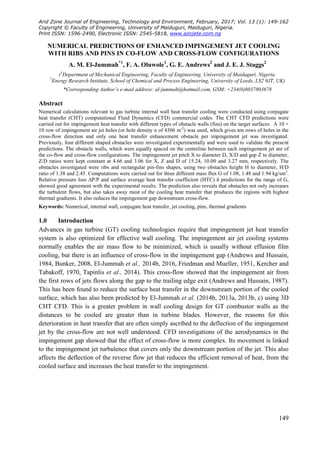
(i) Experimental test rig (ii) Experimental obstacles target plates
Figure 1: Impingement Heat Transfer cooling experimental rig and test walls schematic diagrams
jet surface. Andrews et al. (2003, 2006) experimentally, used the test rig of Figure 1 (i) and the test
walls of Figure 1 (ii), as typical obstacle walls (fins) to investigate these effects and also augment
the impingement cooling heat transfer of gas turbine hot walls. The present CHT CFD work,
investigates their experimental results for the ribs and pins in co- and cross-flows alignments.
1.1 Review on Impingement Heat Transfer Enhancement
The use of obstacles as flow turbulators have been shown to augment heat transfer in GT cooling
channels and the typically used obstacles are the ribs wall, rectangular pin, dimples, pin-fins or
cylindrical pins, bumps and perforated ribs. However the literature on the addition of various
turbulators in the impingement gap, shows that enhancing the already high impingement heat
transfer is quite difficult and a 20 % increased would be a good optimization. Andrews et al.
(2003), Abdul Husain and Andrews (1991), Trabold and Obot (1987), Spring et al. (2012) and
Taslim and Fong (2011) have experimentally investigated ribs walls at 90o
with the impingement
jet flows across the ribs. Spring et al. (2012) investigation was with the application of CFD using
SST model, the predictions were to near 10 % agreement with their experimental average h and
with over 50 % local h, but with test wall differences for the two conditions. The results for their
in-lined ribs arrangement showed heat transfer degradation due to increased cross-flow effects,
while for the staggered arrangement 20 - 50 % enhancement downstream from row 5 was recorded.
Trabold and Obot (1987) investigated ribbed wall cross-flow for two jet exit flows and found better
enhancement for the maximum scheme exit flows. They showed heat transfer degradation at the
upstream due to induced cross-flow and downstream enhancement based on X/D effects. Taslim et
al. (2001) combined radial ribs with bumps for combined impingement jet and film cooling,
enhancement due to the bumps in the presence of film cooling holes was shown. They also showed
65 % enhancement h in the present of showerhead film cooling holes and 35 % enhancement, for
only the conical bumps and without film holes. Hoefler et al. (2012) investigated ribbed surfaces
using staggered oblique impingement jets that were inclined with the ribs aligned to the jets,
enhancement from 12 - 27 % were recorded at 25 % surface increment. Impingement heat transfer
enhancements have also been used on heated cubes, using numerical approach for varied Reynolds
3. El-Jummah et al.: Numerical Predictions of Enhanced Impingement Jet Cooling with Ribs and Pins in Co-
flow and Cross-flow Configurations.
AZOJETE, 13(1):149-162 ISSN 1596-2490; e-ISSN 2545-5818, www.azojete.com.ng
151
number Re (Rundstrom and Moshfegh, 2008), flow aerodynamics were predicted from the
analysis.
The used of ribbed walls have also been applied by several authors to gas turbine cooling
applications. Wang et al. (1998) investigation was using inclined ribs configurations in a film
cooling system, whereby flow and thermal fields were predicted using 2D CFD. Chung et al.
(2014) investigated inclined ribs that intersected in a duct for internal cooling of GT turbine blades.
Andrews et al. (2003) investigated ribs parallel to the impingement jet cross-flow that gave a small
increment in heat transfer, as compared to smooth surface. In the downstream section of the cross-
flow duct, the enhancement at low G was as high as 30 % for the best rib geometry. But for the
surface averaged heat transfer, this was only 10 - 20 % enhancement at low G and no enhancement
at high G. They found that there was an improved enhancement if the ribs were slotted and of
greater height relative to the duct, this gave a rectangular pin geometry, which is modelled in the
present work. Shizuya and Kawaike (1987) investigated a wide range of enhanced impingement
cooling configurations, the most effective was a 50 % improvement in heat transfer using
cylindrical pin-fins in a square array as compared to a smooth wall. Azad et al. (2002) also
investigated impingement jet cooling heat transfer enhancement using pin-fins for a 4 × 12 holes
for three coolant mass flows and with five pins serving each jet flow. A recent development in
enhanced heat transfer is the application of dimple obstacles in the target surface, Xie et al. (2013)
studied three different dimple obstacles configurations and found that the optimum heat transfer
was for a dimple depth δ to its diameter Do, ratio δ/Do of 0.3, which was the largest investigated.
Ligrani et al. (2003) and Ligrani (2013) reviewed heat transfer enhancement as applied to internal
cooling of turbine components, they concluded that ribbed wall obstacles gave a higher heat
transfer enhancement.
1.2 The Test Walls Previous Experimental Procedure
The experimental techniques have been fully detailed by previous investigators, the test rig shown
in Figure 1 (i), have been used experimentally as stated above, in investigating the enhanced
impingement heat transfer. This was for two types of obstacles (fins): ribs and rectangular pins,
with two cross-flow alignments of co- and cross-flow as in Figure 1 (iia - d). The pins obstacle
heights were higher than for ribs and both were designed to have the same total fin area. The test
walls had ribs machined from a solid block of stainless steel. The rectangular pins or slotted ribs
were intended to generate more turbulence in channel flow or co-flow as seen in Figure 1 (iia and
c) and large scale recirculation and enhanced turbulence in cross-flow as in Figure 1 (iib and d).
The co-flow arrangement of the obstacle walls, gave low blockage of 5.8 % for ribs and 10.4 % for
the rectangular pin-fins to the flow, hence would have a low enhancement of the pressure loss.
While the rib transverse to the cross-flow with 50 % of the total cross-flow area blocked and 80 %
for the rectangular pin. The aim was to utilise the internal impingement jet recirculating flow in the
gap and the cross-flow to scrub the fins and enhance the heat removed from the wall. The main
design aim was to utilise additional surface area for heat transfer and to use the rectangular pin-fins
to investigate whether the turbulence generated was beneficial relative to the increase in pressure
loss that would occur. Experimentally, the heat transfer surface area was taken as the same as that
of the smooth wall by ignoring the increase in surface area due to the obstacle walls. Currently, this
experimental procedure could likely affect the predictions, as the exact methods followed in
4. Arid Zone Journal of Engineering, Technology and Environment, February, 2017; Vol. 13 (1):149-162
ISSN 1596-2490; e-ISSN 2545-5818, www.azojete.com.ng
152
removing the obstacle wall may also include in the CHT CFD the heated portion of the solid
therein.
2.0 CFD Methodology
2.1 Model Grid Geometry
The geometries modelled in this work, have the same configuration with the smooth impingement
target wall geometries that were used for single exit cooling experimental investigation. Table 1
summarised the 10 × 10 array of impingement jet holes (El-Jummah, 2014a, b, 2013a) geometry
that was tested, for varied coolant mass flux G from 1.08 - 1.93 kg/sm2
. The smooth wall results
have been predicted by El-jummah et al. (2013a) with good agreement with the experimental
surface average HTC and the gap exit pressure loss. This work investigates using the same
geometrical configurations as Figure 2 (i) show, the potential improvement in the heat transfer
using obstacle walls on the target surface, as in Figure 1 (ii) with dimensions in Table 2 and Figure
2 (ii). The obstacle walls were those investigated by Andrews et al. (2003, 2006) and Abdul
Hussain and Andrews (1991) with a fin thickness t, of 3 mm, as shown in Figure 2 (iia). The ribs
consisted of a continuous rib of height H that was 45 % of Z as in Figure 2 (iia) or rectangular pin
with H as 80 % of Z as in 2 (iib or c) with equal pin width W and pin gap. These two obstacles
were investigated for two cross-flow directions relative to the fins: co-flow parallel to the fins and
cross-flow which is across. Figure 3 show the symmetrical elements of the control volumes that
were used in modelling the model grids geometries of Figure 4, 3a for the ribs wall in cross-flow
and 3b for rectangular pin in co-flow. The blockage of the obstacles was greater in the cross-flow
direction and so the pressure loss increased was higher.
Table 1: Geometric Variables
Variables Dimensions
D (mm) 3.27
X (mm)
Z (mm)
15.24
10.0
L (mm)
L/D
6.35
1.94
X/D 4.66
Z/D
X/Z
3.06
1.52
n 4306 m-2
Array 10 × 10
Table 2: Obstacle Walls Parameters
Types W (mm) H (mm) t (mm) H/W
RW: co-flow continuous 8.00 3.0
RW: cross-flow continuous 8.00 3.0
RP: co-flow 8.59 4.50 3.0 0.93
RP: cross-flow 8.59 4.50 3.0 0.93
5. El-Jummah et al.: Numerical Predictions of Enhanced Impingement Jet Cooling with Ribs and Pins in Co-
flow and Cross-flow Configurations.
AZOJETE, 13(1):149-162 ISSN 1596-2490; e-ISSN 2545-5818, www.azojete.com.ng
153
(i) Geometrical setup and flow scheme (ii) Cross-section and dimensions of the obstacles
Figure 2: The 3D symmetrical elements of the model geometry
(a) Ribs wall: cross-flow (b) Rectangular pin: co-flow
Figure 3: Symmetrical elements of the computational domains
(a) Ribs wall: cross-flow model geometry (b) Rectangular pin: co-flow model geometry
Figure 4: Grid model geometries with the obstacle walls on target surface
Figure 5: The model grids of the obstacle walls on the impingement target surface
6. Arid Zone Journal of Engineering, Technology and Environment, February, 2017; Vol. 13 (1):149-162
ISSN 1596-2490; e-ISSN 2545-5818, www.azojete.com.ng
154
The gap between the top of the rectangular pin is necessary to allow for thermal expansion as the
wall and rib are hotter than the impingement wall. If there was a solid connection, differential
thermal expansion would create thermal stresses and cracking. Figure 4 (a and b) show the
hexahedral computational grid that was modelled using the symmetrical representation of Figure 3
(a and b), which are one row of impingement half holes that were generated using ANSYS ICEM
meshing tool for y+
~35 as Table 3 show. For each obstacle arrangement and for each G, as in
Figure 5 (a - d) and as Table 4 show, an entirely new model grid geometry has to be modelled in
order to achieve a successful computation. The obstacles in co-flow were modelled on the
symmetry plane between holes, which involved half the obstacle width, while the cross-flow
obstacles were modelled using the whole obstacle width. For all the obstacle grid model
geometries, a minimum total cells size of 1.35 × 10⁶
for the low G and ~1.45 × 10⁶
maximum for
the highest G were modelled, Table 3 show the parts percentage grids.
Table 4 Flow Conditions
G (kg/sm2
) 1.93 1.48 1.08
Vj (m/s) 43.41 33.5 24.3
Uc (m/s) 24.0 18.4 13.4
Vj/Uc 1.8 1.8 1.8
Reh 9680 7440 5400
T∞(K) 288 288 288
Tw (K) 353 353 353
ρ (kg/m3
) 1.225 1.225 1.225
2.2 Model Computation and Procedures
Bailey and Bunker (2002) and Spring et al. (2012) applied a low Re turbulence model (SST) and
predicted the locally HTC h on the target plates, El-jummah et al. (2014a, b) applied high Reynolds
Re (= ρVjD/μ) model in predicting their available locally surface average h and aerodynamics,
while Shariff and Mothe (2009, 2010) predicted locally h with low and aerodynamics with high Re
models. Bailey and Bunker (2002) also used high Re in predicting the aerodynamics pressure loss.
El-jummah et al. (2014a, b, 2013a) predicted cases of wall conductive heat transfer for conditions
were Biot numbers < 0.2, using a high Re standard k - ɛ turbulence model, which this work is also
employing. This CHT CFD incorporates both fluid and solid zones as in Figure 5 using the high Re
turbulence model already validated. This is because the flow aerodynamics in the impingement
gap is a major aspect of the flow and these includes strong flow recirculation, which the k - ε model
has shown good predictions.
The obstacle walls model grids were computed for varied G of 1.08, 1.48 and 1.98 kg/sm2
,
respectively using ANSYS Fluent solver with a wall function y+
value ~35 as in Table 3. These y+
values have been reported to be in the range 30 < y+
< 300 of the near wall law of the wall values.
Table 4 show the model computational flow conditions that were used and are those used by El-
jummah et al. (2013a). The convergence criteria were set at 10-5
for continuity, 10-11
for energy
and 10-6
for k, ɛ and momentum (x, y and z velocities), respectively. The minimum orthogonal
quality and aspect ratio, for all the geometries modelled were fixed at 0.61 and 3.53, respectively.
The number of cells in all computational zones have been shown to be adequate based on grid
sensitivity tests by El-jummah et al. (2013b, c). Typical of these cell zones are in the holes, where
flow separation and reattachment dominates, impingement gap duct flow where the exit pressure
Table 3 Percentage of Parts Grids for y+
~35
Types Parts (%)
Test walls Obstacles Gap Holes
RW: co-flow 28.5 8.1 19.7 8.4
RW: cross-flow 28.5 8.1 19.7 8.4
RP: co-flow 28.5 7.2 20.6 8.4
RP: cross-flow 28.5 7.2 20.6 8.4
7. El-Jummah et al.: Numerical Predictions of Enhanced Impingement Jet Cooling with Ribs and Pins in Co-
flow and Cross-flow Configurations.
AZOJETE, 13(1):149-162 ISSN 1596-2490; e-ISSN 2545-5818, www.azojete.com.ng
155
loss and target surface heat transfer are most significant and the test walls where the thermal
gradients prevails. Second-order discretization for momentum and first-order discretization, for
TKE and dissipation of TKE using the PISO schemes based on PRESTO have been employed.
3.0 Computational Results
3.1 Influence of Aerodynamics on the Velocity Profiles
The aerodynamics in the impingement gap is complex, as was predicted by El-jummah et al. (2015,
2016, 2013b) using CHT CFD modelling. The additions of obstacles to the target wall was aimed
at increasing the heat transfer by inserting the obstacles at the location of the reverse flow between
each impingement jet. This increases the complexities of the aerodynamics as the cross-flow builds
up with succesive rows of impingement jets. Figures 6 (ia - d) show the flow velocity profiles for
all the obstacle geometries, which are for the symmetry planes of the jet holes. Figures 6 (i) clearly
show that the flow-maldistribution (predicted velocity in the hole normalized to the mean using
Equation 1) between the holes that were presented in Figure 6 (ii), are the influence of the peak
velocity scales in the downstream holes. The comparison of the predictions of all the obstacles
geometries shows that the influence of the cross-flow are greater, as the mean cross-flow velocities
are higher and at a peak in the plane of the obstacles (or between the holes) as in Figure 7 (i). For
the obstacle walls of cross-flow, the deflection of the jet by the higher cross-flow velocity over the
walls is quite high, which is expected to generate higher turbulence hence good cooling. In the
downstream cooling, the deflected jets impinges on the upstream face of the walls and this will
produce good cooling there, as shown by Figure 7 (ii) and predicted using the normalized
temperature (or thermal gradient) T*
of Equation 2. Figure 6 (i) and ii reveals that the co-flow
geometries have insignificant jet deflections as the flow in the downstream holes is relatively close
to the upstream one, as Figure 6ii shows, this flow is quite higher at downstream than for the cross-
flow geometry. Figure 7 (ii) shows that lowest thermal gradients exist in the rectangular pin
obstacles, this expected as the gap blockage is the minimum.
( ) ( ) ( )
( )
( )
( )
3.2 Predicted Axial Pressure Loss Profiles
The cross-flow obstacles create a blockage to the cross-flow downstream the impingement gap
(Abdul Husain and Andrews, 1991, Andrews et al., 2003), as in Table 2. This increases the
pressure loss shown in Equation 1 due to the cross-flow as Figure 8a show to leads to an increased
flow-maldistribution between the impingement holes for all the cross-flow configurations, which
block the downstream cross-flow. Figure 7 shows that the co-flow obstacles that have the minimum
blockage to the cross-flow have a flow-maldistribution similar to the smooth wall predictions of El-
jummah et al. (2014b, 2013a), which have similar relative pressure loss ∆P/P as in Figure 8a. The
downstream impingement gap cross-flow over the obstalces leads to higher ∆P/P as shown in
Figure 8a. The increased flow-maldistribution with obstacles also creates a lower pressure loss
across the leading
8. Arid Zone Journal of Engineering, Technology and Environment, February, 2017; Vol. 13 (1):149-162
ISSN 1596-2490; e-ISSN 2545-5818, www.azojete.com.ng
156
(i) Velocity magnitude (m/s) in the plane of the holes (ii) Flow-maldistribution in the impingement
jet holes
Figure 6: Influence of flow aerodynamics with obstacles in impingement holes for G of 1.93 kg/sm2
(i) Velocity magnitude (m/s) in the obstacles plane (ii) Normalized temperature in the obstacles plane
Figure 7: Impingement gap distributions of flow and heat in the fluid and walls for G of 1.93 kg/sm2
The holes in the gap, which is the effect that gives rise to the increased flow-maldistributoin in
Figure 7 (ii). Figure 8a shows that the cross-flow obstacle geometries are predicted to have higher
pressure loss than the co-flow geometries, which was expected as there was increased cross-flow
velocity in the gap with blockage. However, the reduced ∆P/P for co-flow with ribs was
unexpected, it appears that as the rib prevents the impingement flow of adjacent jets in the
transverse direction, it changes the reverse flow jet in a way that reduces its impact on the cross-
flow ∆P/P. This pressure loss will also be seen to influence the heat transfer that will be predicted
using Equation 3.
( )
( )
9. El-Jummah et al.: Numerical Predictions of Enhanced Impingement Jet Cooling with Ribs and Pins in Co-
flow and Cross-flow Configurations.
AZOJETE, 13(1):149-162 ISSN 1596-2490; e-ISSN 2545-5818, www.azojete.com.ng
157
(a) Impingement hole outlet pressure loss (b) Impingement gap exit pressure loss for all G
Figure 8 Effects of mass flux G in the impingement hole and gap exits aerodynamics
(a) Surface average HTC validation (b) Nusselt number over smooth average one
Figure 9: Comparison of predicted and measured/CFD heat transfer for the range of flow values
3.3 Validation of CFD Predictions
Figure 8b compares the measured (Abdul Husain and Andrews, 1991, Andrews et al., 2003, 2006)
and predicted pressure loss, from the air feed plenum static pressure to the impingement gap exit
static pressure well downstream of the last obstacle, which is the overall wall relative pressure loss
∆P/P. The ∆P/P predictions for range of G values that were shown in Table 4 for the co-flow
obstacles and that for the rectangular pin cross-flow gave excellent agreement with the
measurements, but the ribs wall cross-flow obstacle shows slightly higher predicted pressure loss.
The reason for this was that in cross-flow continuous ribs, the distance downstream of the last
obstacle for the flow to have recovered the dynamic pressure due to flow acceleration was longer
than the computational domain. These predicted and measured pressure loss agreements indicate
that the aerodynamics was adequately modelled. The two continuous rib designs would be
expected to increase the pressure loss as they have a 45% blockage (Table 2 based on H design) of
the cross-flow and both force the cross-flow to deflect towards the impingement jet wall. The full
height of the impingement gap is available for the downstream cross-flow in these designs, whereas
the continuous ribs force this cross-flow to separate from the surface, which appears to be the key
reason for the increased in pressure loss for the continuous ribs in cross-flow.
10. Arid Zone Journal of Engineering, Technology and Environment, February, 2017; Vol. 13 (1):149-162
ISSN 1596-2490; e-ISSN 2545-5818, www.azojete.com.ng
158
It has previously been shown that the present CFD procedures, predicted the measured smooth wall
impingement heat transfer results (El-Jummah et al., 2014b, 2013a, 2013b, c). The predictions of
the target surface average HTC h on the influence of obstacle walls are compared with the
measured HTC (Abdul Husain and Andrews, 1991, Andrews et al., 2003, 2006) in Figure 9a and
were based on Equation 3. All the predictions for the surface averaged HTC are within 12 % of the
measurements at all G, as generally any error is an under prediction. For the continuous rib with
co-flow, the agreement was perfect with no significant error at any G. For the rib wall in cross-
flow, the predictions were 6 % low at low G and 3 % low at high G. For the rectangular pin fin in
co-flow the predictions were also in good agreement at all G. For the rectangular pin fins in cross-
flow the predictions were 8 % low at high G and 12 % low at low G. The more complex is the
interactions of cross-flow with the obstacle, the higher the error that was found. However, these
predictions for most of the geometries are sufficiently close to the measured ± 10 % error (El-
Jummah et al., 2014b) bars in Figure 9a to have confidence that surface averaged h were reliably
predicted. The predicted enhanced target surface averaged Nusselt number Nu variations based on
Equation 4, averaged over the smooth target average Nusselt number Nu (El-Jummah et al., 2014b)
as a function of Reynolds number Re is shown in Figure 9b. The co-flow obstacles predicted the
average Nu to be above that of the smooth target walls, while cross-flow obstacles are below. This
indicates that most of the cooling has been taking away by the cross-flow obstacle walls.
(a) Target surface X2
average HTC h (b) Wall normalized thermal gradients
Figure 10: Predicted conjugate heat transfer of the obstacle walls for range of G values
( )
11. El-Jummah et al.: Numerical Predictions of Enhanced Impingement Jet Cooling with Ribs and Pins in Co-
flow and Cross-flow Configurations.
AZOJETE, 13(1):149-162 ISSN 1596-2490; e-ISSN 2545-5818, www.azojete.com.ng
159
Figure 11: Contours of Nusselt number on the target wall with the obstacles for G of 1.93 kg/sm2
The above assertion for the cross-flow obstacles, are further shown in Figure 10a which is the
predicted locally X2
averaged h in the absences of the obstacles. It shows that the downstream X2
averaged h cooling of the cross-flow geometries is insignificant as compared to the co-flow,
whereby at the upstream last holes the cooling is above the later. This must be the reason for the
surface average better cooling shown in Figure 9b that the co-flow Nu predictions are above cross-
flow ones. The thermal gradients through the combined target and obstacles walls for the obstacles
at the hole 9 position are predicted in Figure 10b, whereby the smooth wall predictions are shown
for comparison. The lowest thermal gradients T*
are predicted in Figure 10b to be in the region
close to the jet plates. The ribs obstacles gave higher thermal gradients, with the pin fins having the
greatest gradients, which was based on the impingement gap blockage as pins have the highest.
3.4 Surface Distribution of Nusselt Number
Figure 11 shows the CHT CFD predicted surface distribution of Nusselt number Nu on the
enhanced target surface, predicted using Equation 4, where left side is Nu with the obstacles and
right side without. The Nu surface distribution is very similar to that of the TKE in Figure 12 (i)
which gave rise to Figure 12 (ii). Figure 11 shows that most the cooling Nu are either between the
obstacles typical of the co-flow or on the obstacles for the cross-flow and lower Nu values are on
the upstream obstacles. Any enhancement of heat transfer has to come from the heat transfer to the
rib or pin fin surfaces, which is not shown in Figure 11. The quite poor Nu distribution for the
rectangular pin on the target surface is partially compensated for by the heat transfer on the cross-
flow obstacle surfaces, which extract heat from the target surface by conduction. The heat transfer
to the obstacle surfaces was shown in Figure 9b, which shows the high heat transfer on the rib and
rectangular pin fins surfaces in the downstream part of the flow, where the cross-flow deflects the
jets strongly onto the rib in cross-flow surface.
12. Arid Zone Journal of Engineering, Technology and Environment, February, 2017; Vol. 13 (1):149-162
ISSN 1596-2490; e-ISSN 2545-5818, www.azojete.com.ng
160
(i) Turbulence kinetic energy for G of 1.93 kg/sm2
(ii) Normalized temperature for G of 1.93 kg/sm2
Figure 12: Enhanced target surface distribution of TKE and T*
showing the influence of obstacles
3.5 Temperature Gradients through Enhanced Walls
Fig (ii) shows the enhanced target surface distribution of normalised temperature T*
of all the
obstacle walls, found using Equation 2. The region of the lowest distributions of T*
indicates the
region with the higher HTC or Nu (based on Equations 3 or 4). Fig) show that the lowest surface
temperatures and temperature distribution were for the upstream co-flow region, this is the region
of the highest TKE shown in Figure 12 (i). This was due to the reduced impingement cooling by
the obstacle walls, which normally is unexpected as the walls takes away most of the cooling
(Figure 11 left hand side). The configuration for the downstream cross-flow rib-wall obstacle
showed very good cooling, but the implication could be inadequate overall cooling and increased
flow-maldistribution as in Figure 6ii. This affects the upstream thermal gradient as in Figure 12ii
(a) as the influence of TKE is very much pronounced at that region as Figure 12 (ia) show and is
the region of the pick turbulence. Figure 7 (iic and d), shows that the better cooled obstacles are
that for the high blockage wall, as also shown by Figure 11 (c and d).
4.0 Conclusions
The CHT CFD predictions of the enhanced impingement heat transfer for G of 1.08, 1.48 and 1.93
kg/sm2
at fixed X/D of 4.66 and Z/D of 3.06 showed good agreement with the experimental surface
average HTC. The predictions of the pressure loss were in very good agreement with the
measurements, indicating that the aerodynamics were adequately predicted.
The predictions showed that it was difficult to enhance the smooth wall impingement heat transfer
and that obstacles could deteriorate the heat transfer. The main effect of the obstacles was to
enhance the heat transfer to the impingement jet wall and decrease it to the target wall. A small
increase in the overall surface average heat transfer was predicted for the co-flow configuration
with ribs.
The geometrical model design and the predicted results for the enhancement cooling in gas turbine
system showed that design optimisation using CHT CFD tool could be reliable.
13. El-Jummah et al.: Numerical Predictions of Enhanced Impingement Jet Cooling with Ribs and Pins in Co-
flow and Cross-flow Configurations.
AZOJETE, 13(1):149-162 ISSN 1596-2490; e-ISSN 2545-5818, www.azojete.com.ng
161
References
Abdul Husain, RAA. and Andrews, GE. 1991. Enhanced Full Coverage Impingement Heat
Transfer With Obstacle in the Gap. Proc. ASME Int. Gas Turbine & Aeroengine Congress &
Eposition, 91-GT-346, 1 - 12.
Andrews, GE., Abdul Husain, RAA. and Mkpadi, MC. 2003. Enhanced Impingement Heat
Transfer: Comparison of Co-Flow and Cross-flow with Rib Turbulators. Proc. GTSJ Int. Gas
Turbine Congress, IGTC TS-075 1 - 8.
Andrews, GE., Abdul Husain, RAA. and Mkpadi, MC. 2006. Enhanced Impingement Heat
Transfer: The Influence of Impingement X/D for Interrupted Rib Obstacles (Rectangular Pin Fins).
Trans. ASME J. Turbomachinery, 128, 321 - 331.
Andrews, GE. and Hussain, CI. 1984. Impingement Cooling of Gas Turbine Components. High
Temperature Technology, 2 (2), 99 - 106.
Andrews, GE. and Hussain, CI. 1987. Full Coverage Impingement Heat Transfer: The Influence of
Cross-Flow. AIAA/SAE/ASME/ASEE 23rd Joint Propulsion Conference, AIAA-87-2010, 1 - 9.
Azad, GMS., Huang, Y. and Han, J. 2002. Jet Impingement Heat Transfer on Pinned Surfaces
Using a Transient Liquid Crystal Technique. Taylor & Franscis Int. J. Rotating Machinery, 8 (3),
161 - 173.
Bailey, JC. and Bunker, RS. 2002. Local Heat Transfer and Flow Distributions for Impinging Jet
Arrays of Dence and Sparse Extent. Proc. ASME Turbo Expo, GT-30473, 1 - 10.
Bunker, RS. 2008. The Effects of Manufacturing Tolerances on Gas Turbine Cooling. Proc ASME
Turbo Expo, GT-50124, 1 - 16.
Chung, H., Park, SJ., Park, S., Choi, SM., Cho, HH. and Rhee, DH. 2014. Augmentated Heat
Transfer for a Angled Rib With Intersecting Rib in Rectangular Channels of Different Aspect
Ratios. Proc. ASME Turbo Expo, GT-26924, 1 - 13.
El-Jummah, AM., Abdul Hussain, RAA., Andrews, GE. and Staggs, JEJ. 2014a. Conjugate Heat
Transfer CFD Predictions of Impingement Heat Transfer: Influence of the Number of Holes for a
Constant Pitch to Diameter Ratio X/D. Proc. ASME Gas Turbine Conference, GT-25268, 1 - 14.
El-Jummah, AM., Abdul Hussain, RAA., Andrews, GE. and Staggs, JEJ. 2014b. Conjugate Heat
Transfer Computational Fluid Dynamic Predictions of Impingement Heat Transfer: The Influence
of Hole Pitch to Diameter Ratio X/D at Constant Impingement Gap Z. Trans. ASME J.
Turbomachinery, 136 (12), 1 - 16.
El-Jummah, AM., Andrews, GE. and Staggs, JEJ. 2015. CHT/CFD Predictions of Impingement
Cooling With Four Sided Flow Exit. Proc. ASME Turbo Expo, GT-42256 1 - 12.
El-Jummah, AM., Andrews, GE. and Staggs, JEJ. 2016. Impingement Jet Cooling with Ribs and
Pin Fin Obstacles in Co-flow Configurations: Conjugate Heat Transfer Computational Fluid
Dynamic Predictions. Proc. ASME Turbo Expo: Turbomachinery Technical Conference &
Exposition, GT- 57021, 1 - 15.
El-Jummah, AM, Abdul Hussain, RAA., Andrews, GE. and Staggs, JEJ. 2013a. Conjugate Heat
Transfer CFD Predictions of the Surface Averaged Impingement Heat Transfer Coefficients for
Impingement Cooling with Backside Cross-flow. Proc. ASME IMECE Conference, IMECE-63580,
1 - 14.
El-Jummah, AM. Andrews, GE and Staggs, JEJ 2013b. Conjugate Heat Transfer CFD Predictions
of Impingement Jet Array Flat Wall Cooling Aerodynamics with Single Sided Flow Exit. Proc.
ASME Turbo Expo Conference, GT-95343, 1 - 12.
El-Jummah, AM. Andrews, GE. and Staggs, JEJ. 2013c. Conjugate Heat Transfer CFD Predictions
of the Influence of the Impingement Gap on the Effect of Cross-Flow. Proc. ASME Heat Transfer
Conference, HT-17180, 1 - 12.
14. Arid Zone Journal of Engineering, Technology and Environment, February, 2017; Vol. 13 (1):149-162
ISSN 1596-2490; e-ISSN 2545-5818, www.azojete.com.ng
162
Friedman, SJ. and Mueller, AC. 1951. Heat Transfer to flat surfaces Proc. IMechE: General
Discussions on Heat Transfer, 138 - 142.
Hoefler, F., Schueren, S., Wolfersdorf, J. and Naik, S. 2012. Heat Transfer Characteristics of an
Oblique Jet Impingement Configuration in a Passage With Ribbed Surfaces. Trans. ASME J.
Turbomachinery, 134, 1 - 9.
Kercher D. M. and Tabakoff W. 1970. Heat Transfer by a Square Array of Round Air Jets
Impinging Perpendicular to a Flat Surface Including Effect of Spent Air. Trans. ASME J. Eng.
Power, 73 - 82.
Ligrani, PM. 2013. Review Article: Heat Transfer Augmentation Technologies for Internal Cooling
of Turbine Components of Gas Turbine Engines. Hindawi Int. J. Rotating Machinery, 2013, ID.
275653, 1 - 32.
Ligrani, PM., Oliveira, MM. and Blaskovich, T. 2003. Comparison of Heat Transfer Augmentation
Techniques. AIAA Journal, 41 (3), 337 - 362.
Rundstrom, D. and Moshfegh, B. 2008. Investigation of Heat Transfer and Pressure Drop of an
Impinging Jet in a Cross-Flow Cooling of Heated Cube. Trans. ASME J. Heat Transfer, 130, 1 -
13.
Sharif, MAR. and Mothe, KK. 2009. Evaluation of Turbulent Models in the Prediction of Heat
Transfer Due to Slot-Jet Impingement on Plane Concave Surfaces. Taylor & Franscis Numerical
Heat Transfer, Part B, 55, 273 - 294.
Sharif, MAR. and Mothe, KK. 2010. Parametric Study of Turbulent Slot-Jet Impingement Heat
transfer from Concave Cylindrical Surfaces. Elsevier Int. J. Thermal Sciences, 49, 428 - 442.
Shizuya, M. and Kawaike, K. 1987. Experimental Investigation of Blade Internal Cooling Methods
Using Ribs and Fins. Proc. GTSJ Int. Gas Turbine Congress, IGTC-65, 159 - 166.
Spring, S., Xing, Y. and Weigand, B. 2012. Experimental and Numerical Study of Heat Transfer
from Arrays of Impinging Jets With Surface Ribs. ASME J. Heat Transfer, 134, 1 - 11.
Tapinlis, O., Choi, M., Gillespie, DRH., Lewis, LV. and Ciccomascolo, C. 2014. The Effect of
Impingement Jet Heat Transfer on Casing Contraction in a Turbine Case Cooling System. Proc.
ASME Turbo Expo, GT-26749, 1 - 11.
Taslim, ME. and Fong, MKH. 2011. Experimental and Numerical Crossover Jet Impingement in a
Rib-Roughened Airfoil Trailing-Edge Cooling Channel. Proc. ASME Turbo Expo, GT-45995, 1 -
12.
Taslim, ME., Pan, Y. and Spring, SD. 2001. An Experimental Study of Impingement on
Roughened Airfoil Leading-Edge Walls With Film Holes. Trans. ASME J. Turbomachinery, 123,
766 - 773.
Trabold, TA. and Obot, NT. 1987. Impingement Heat Transfer Within Arrays of Circular Jets: Part
II - Efects of Cross-Flow in the Presence of Roughness Elements. Trans. ASME J.
Turbomachinery, 109, 594 - 601.
Wang, Z., Ireland, PT., Kohler, ST. and Chew, JW. 1998. Heat Transfer Measurements to a Gas
Turbine Cooling Passage With Inclined Ribs. Trans. ASME J. Turbomachinery, 120, 63 - 69.
Xie, Y., Li, P., Lan, J. and Zhang, D. 2013. Flow and Heat Transfer Characteristics of Single Jet
Impinging on Dimpled Surface Trans. ASME J. Heat Transfer, 135, 1 - 15.