Download to read offline

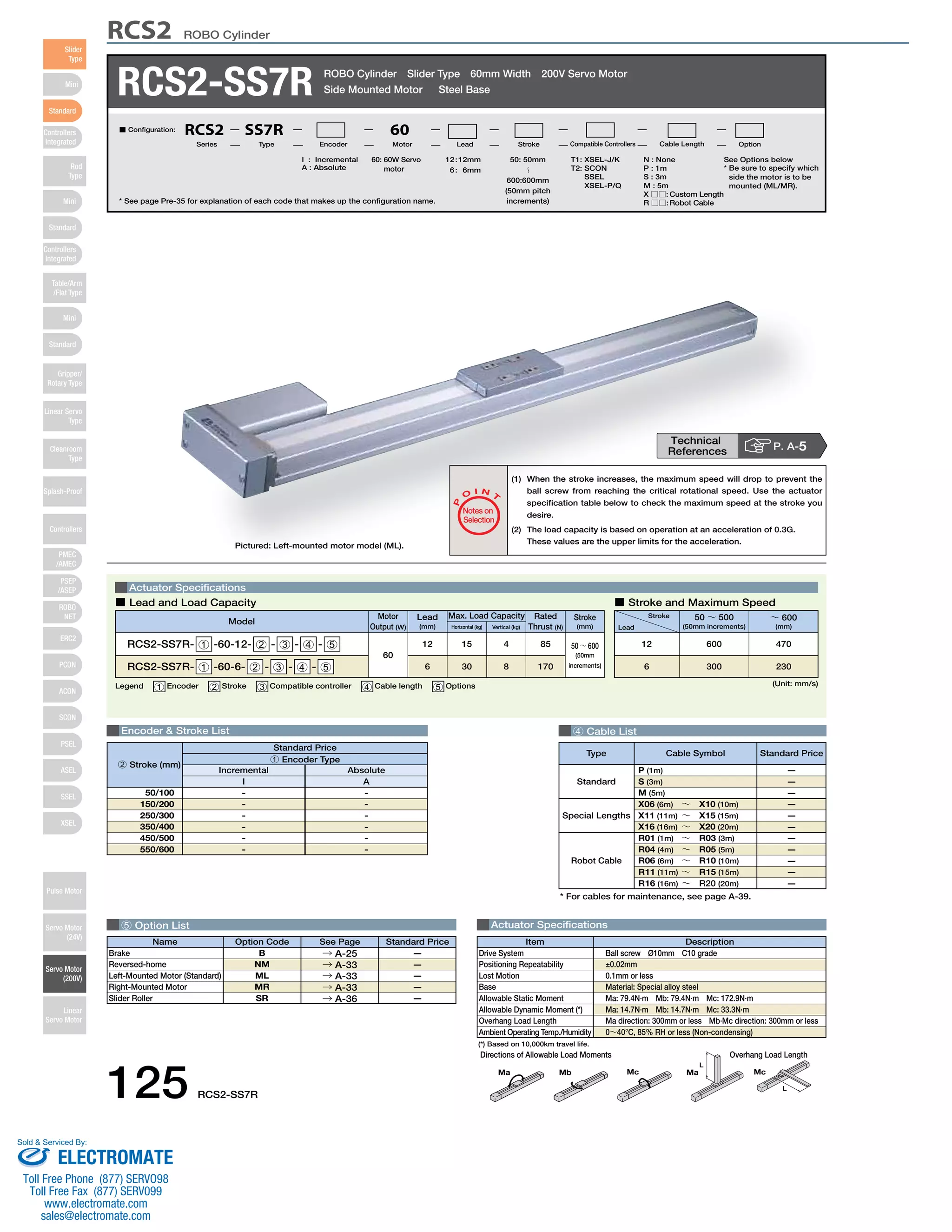
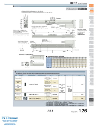

This document provides specifications for the RCS2-SS7R ROBO Cylinder actuator. It includes details on its servo motor, stroke lengths from 50-600mm, load capacities, dimensions, compatible controllers, and cable options. Accessories include brakes and options for left or right mounted motors. Technical references and a sales contact are provided at the end.


