SlideShare a Scribd company logo
1 of 64
1 | P a g e
EXPERIMENT-1
OBJECTIVE
A comparative study of working principle and applications of
various non-conventional machining processes.
ELECTRICAL DISCHARGE MACHINING
 Basic Principle
Itis a process of metal removalbased on the principle of material removal
by an interrupted electric spark discharge between the electrode tool and
the work piece as shown in figure 1.1. In EDM, a potential difference is
applied between the tool and work piece. Essential - Both tool and work
material are to be conductors. The tool and work material are immersed
in a dielectric medium. Generally kerosene or deionised water is used as
the dielectric medium. A gap is maintained between the tool and the work
piece.
Figure 1.1 Basic Principle of Electro-Discharge Machining process
2 | P a g e
Depending upon the applied potential difference (50to 450V) and the gap
between the tool and work piece, an electric field would be established.
Generally the tool is connected to the negative terminal (cathode) of the
generator and the work piece is connected to positive terminal (anode).
 Effect of process parameters on Material Removal Rate
and Surface Roughness
There are severalparameters which affect performanceof process. Some
of them are given as below
1. Mean current
2. Frequency
3. Spark gap
4. Dielectric fluid supply
5. Pulse on time
6. Pulse off time
 Meancurrent
Figure 1.2 shows variation of MRR with mean Current across capacitor
in relaxation circuit. Fromthe graph it can be seen that as mean current
is increased MRR increases.
Figure 1.2 Effect of mean current on material removal rate
3 | P a g e
Two important process parameters in EDM are discharge current and
frequency of discharges. As either of these parameters is increased,
metal removal rate increases Surface roughness is also affected by
currentand frequency, as shown in Figure1.3.Thebest surfacefinish is
obtained in EDM by operating at high frequencies and low discharge
currents.
Figure 1.3 Effect of mean current on surface finish
 Spark Gap
A suitable gap is maintained between tool and work piece and is
maintained by servomotor and it is actuated by comparing a reference
voltage and gap breakdown voltagewhich feed tool downward toward
work piece. As spark gap is increaseMRR increases up to highest value,
which is optimum value. Then it starts decrease as shown in fig. 1.4
Figure 1.4 Effect of spark gap on MRR
4 | P a g e
 Pulse on time
The machining process becomes faster after increasing the pulse on
time. By increasingthepulseon time the materialremovalrateincrease
and poor surface finish on the material. Figure 1.5 shows the effect.
Figure 1.5 Effect of Pulse on time on MRR
Accordingto Influenceof InputParameterson theCharacteristicsof the
EDM Process surfacefinish improves on increase in pulse on time. This
result is shown in fig. 1.6
Figure 1.6 Effect of pulse on time on surface roughness
5 | P a g e
 Applications
1. Drilling of micro-holes, thread cutting, helical profile milling, rotary
forming, and curved hole drilling.
2. Delicate work piece like copper parts can be produced by EDM.
3. Can be applied to all electrically conducting metals and alloys
irrespectiveof their melting points,hardness,toughness,orbrittleness.
4. Other applications: deep, small-dia holes using tungsten wire as tool,
narrow slots, cooling holes in super alloy turbine blades, and various
intricate shapes.
5. EDM can be economically employed for extremely hardened work
piece.
6. Sincethere is no mechanical stresspresent(no physicalcontact), fragile
and slender work places can be machined without distortion.
7. Hard and corrosion resistant surfaces, essentially needed for die
making, can be developed
 Advantages
1. Complex shapes that would otherwise be difficult to produce with
conventional cutting tools.
2. Extremely hard material to very close tolerances.
3. Very small work pieces where conventional cutting tools may damage
the part from excess cutting tool pressure.
4. There is no direct contact between tool and work piece. Therefore
delicate sections and weak materials can be machined without any
distortion.
5. A good surface finish can be obtained.
 Limitations
1. The slow rate of material removal.
2. For economic production, diesurfacefinish specified should notbe too
fine.
3. The additional time and cost used for creating electrodes for
ram/sinlcer EDM.
6 | P a g e
4. Reproducing sharp comers on the work piece is difficult due to
electrode wear.
5. Specific power consumption is very high.
6. Power consumption is high.
7. Overcut is formed.
8. Excessive tool wear occurs during machining.
9. Electrically non-conductive materials can be machined only with
specific set-up of the process
 ABRASIVE JET MACHINING
 Basic Principle
In abrasive jet machining (AJM) a focused stream of abrasive grains of
Al2O3 or SiC carried by high-pressuregas or air at a high velocity is made
to impinge on the work surface through a nozzle of 0.3- to 0.5-mm
diameter. The process differs from sandblasting (SB) in that AJM has
smaller diameter abrasives and a more finely controlled delivery system.
The workpiece material is removed by the mechanical abrasion (MA)
action of the high-velocity abrasiveparticles as shown in fig. 1.7. Thework
material is removed by erosion by the high velocity abrasive particles.
Figure 1.7 Basic scheme of Abrasive Jet Machining process
7 | P a g e
Effect of Process Parameterson Material Removal Rate
Process Parameters:
1. Abrasiveflow rate
2. Mixing ratio
3. Gas pressure
4. Velocity of fluid
5. Abrasivegrain size
6. Stand-off distance
 Abrasiveparticle with small grain sizeis used to producesmooth and
fine surface.
 As mass flow rate of the gas in abrasivejet is increases, MRR first
increases until an optimum value and then decrease.
(a) (b)
Figure 1.8 (a) Shows effect of Abrasive flow rate on MRR
(b) Shows effect of mixing ratio on MRR
 MRR increases with increasing in mixing ratio up to optimum value
and then decrease.
 MRR is directly proportionalto velocity of abrasiveparticle and gas
pressure.
 Ifthe densityof abrasiveparticleis gradually increased, theexit velocity
will go on decreasing for the same pressure condition.
8 | P a g e
 It is evident that the increased mass flow rate of abrasivewill result in
decreased velocity of fluid and will thereby cause a decrease in
available energy for erosion and ultimately the material removal rate.
(c) (d)
Figure 1.9 (c) Effect of Abrasive flow rate on MRR while constant mixing
ratio (b) Effect of Gas Pressure on MRR
Applications
 Drilling holes, cutting slots, cleaning hard surfaces, deburring,
polishing and radiusing
 Deburring of cross holes, slots, and threads in small precision parts
that require a burr-freefinish, such as hydraulic valves, aircraftfuel
systems, and medical appliances
 Machining intricate shapes or holes in sensitive, brittle, thin, or
difficult-to-machine materials
 Insulation stripping and wire cleaning without affecting the conductor
 Micro-deburring of hypodermic needles
 Frosting glass and trimming of circuit boards, hybrid circuitresistors,
capacitors, silicon, and gallium
 Removal of films and delicate cleaning of irregular surfaces because
the abrasivestreamis able to follow contours
 Advantage
 Because AJM is a cool machining process, itis best suited for
machining brittle and heat-sensitive materials like glass, quartz,
sapphire, and ceramics.
9 | P a g e
 The process is used for machining super alloys and refractory
materials.
 Itis not reactive with any workpiecematerial.
 No tool changes are required.
 Intricateparts of sharp corners can be machined.
 The machined materials do not experience hardening.
 No initial hole is required for starting the operation as required by
wire EDM.
 Material utilization is high.
 Itcan machine thin materials.
 Limitations
 The removal rate is slow.
 Stray cutting can’t be avoided (low accuracy of 0.1 mm).
 The tapering effect may occur especially when drilling in metals.
 The abrasivemay get impeded in the work surface.
 Suitable dust-collecting systems should be provided.
 Soft materials can’tbe machined by the process.
 Silica dustmay be a health hazard.
 Ordinary shop air should be filtered to remove moistureand oil
ELECTRO-CHEMICAL MACHINIG
 Basic Principle
Electro-chemical machining (ECM) is an inherently versatile process of
machining because of its capability of stress free machining of various
kinds of metals and alloys. It can produce shapes and cavities which are
costly and extremely difficult to machine with the conventional machining
processes and a true replica of the tool (or cathode) can be made on the
workpiece (or anode) by the controlled dissolution of the anode of an
electrolytic cell. The basic scheme of the ECM process has been shown in
Fig. 1.10, in which the tool serving as the cathode and the workpiece
servingasthe anodeof an electrolytic cell havebeen shown.Anelectrolyte
(usually a neutral salt solution such as sodium chloride, sodium nitrate,
10 | P a g e
sodium chlorate) is passed through a very small gap (0.05 to 0.3 mm)
created between the work- piece (or anode) and the tool (or cathode)
whereas a direct current flow is made between them.
Figure 1.10 Basic scheme of the ECM process
When sufficient electrical energy (about 6 eV) is avail- able, a metallic ion
may bepulled outof the workpiecesur-face. The positivemetallic ions will
react with the negative ions present in the electrolytic solution forming
metallic hydroxides and other compounds. Hence, the metal will be
anodically dissoluted with the formation of sludges and precipitates.
Figure 1.11 Schematic principle of Electro-Chemical Machining process
11 | P a g e
 Effect of Process Parameters on Material Removal Rate and
Surface roughness
Process Parameters
1. Electrolyte concentration
2. Voltage
3. Feed rate
4. Electrolyte flow velocity
 MRR is decrease with increasein the electrolyte concentration and
surfaceroughness increaseup to certain level and then decrease.
Figure 1.12 Effect of Electrolyte concentration on MRR and Surface Roughness
 Surfaceroughness is increasewith increase in the voltage. MRR is
increase with increase in voltage in somerang and then decrease.
Figure 1.13 Effect of voltage on MRR and Surface Roughness
12 | P a g e
 MRR and surfaceroughness decreases fastwith increasein feed rate
up to certain value and then increase.
Figure 1.14 Effect of Feed rate on MRR and Surface roughness
 Application
 ECM can be used for machining complicated profiles such as turbine
wheels, turbine and jet engine blades, etc.
 Machining of hard-to-machine and heat-resistant materials.
 Drilling deep holes of small diameter as in nozzles.
 Machining of cavities and holes of irregular shapes.
 Advantage
 There is no wear in the tool because there is no contact between the
tool and the workpiece
 Machining is done at low voltages, compared to other processes, with
high metal removal rates.
 Very small dimensions up to 0.05 mm can be controlled.
 Complicated profiles can be machined easily in a single operation.
 Becauseof the low temperature developed, no thermal damageoccurs
to the workpiece structure.
 Hard conductive materials can be machined.
 The surface finish can be maintained at 0.1 to 1.25 μm Ra.
 Because of its high capital cost, ECM is only suitable for mass
production work
 Labour requirements are low.
13 | P a g e
 Limitations
 A huge amount of energy is consumed (about 100 times that required
for turning or drilling steel).
 Metal removal rates are slow compared with conventional methods.
 ECM can only be applied to electrically conductiveworkpiecematerials.
 There are difficulties in safely removing and disposing of the explosive
hydrogen gas generated during machining.
 The workpiece needs to be cleaned and oiled immediately after
machining.
 There are difficulties with handling and containing the electrolyte,
which may attack the equipment.
 It is not easy to duplicate the shape of the tool electrode in the
workpiecewith a high degreeof accuracybecauseof the sidemachining
effect.
 The process can’t produce sharp internal or external edges.
 The pumping of high-pressure electrolyte into the narrow machining
gap gives rise to large forces acting on the tool and the workpiece.
 ELECTRON BEAM MACHINING
Basic Principle
Electron Beam Machining is process in which high velocity electrons are
concentrated in a narrow beam and then directed towards the workpiece
for machining. When this high velocity electron strikes the workpiece, it
melts and vaporizes the material from the workpiece.
In an electron beam machining, the electrons strike the workpiece with a
high velocity. As the electron strikes the workpiece, the kinetic energy of
the electron changes into heat energy. The heat energy so produced is
used to melt and vaporizethe materials fromthe w/p. The whole process
takes place in vacuum. Vacuum environment is used to prevent the
contamination and avoid collision of electrons with air molecules. If the
electrons collide with the air molecules, it will lost its Kinetic energy.
Electron beamis generated in an electron beam gun. The constructionand
14 | P a g e
working principleof the electron beam gun would be discussed in the next
section. Electron beam gun provides high velocity electrons over a very
small spot size. Electron Beam Machining is required to be carried out in
vacuum. Otherwise the electrons would interact with the air molecules,
thus they would loose their energy and cutting ability. Thus the workpiece
to be machined is located under the electron beam and is kept under
vacuum. The high-energy focused electron beam is made to impinge on
the workpiece with a spot size of 10 – 100 μm. The kinetic energy of the
high velocity electrons is converted to heat energy as the electrons strike
the work material. Due to high power density instant melting and
vaporisation starts and “melt – vaporisation” front gradually progresses,
as shown in Fig. 1.15. Finally the molten material, if any at the top of the
front, is expelled fromthe cutting zoneby the high vapour pressureatthe
lower part. Unlike in Electron Beam Welding, the gun in EBM is used in
pulsed mode. Holes can be drilled in thin sheets using a single pulse. For
thicker plates, multiple pulses would be required. Electron beam can also
be manoeuvredusingthe electromagnetic deflection coils fordrilling holes
of any shape.
15 | P a g e
Figure 1.15 Mechanism of material removal in Electron Beam Machining
Application:
 Electron Beam Machining is used to produce smaller size holes in
various industries like automobile, aerospace, marine etc.
 Drilling of holes in pressure differential devices used in Nuclear
reactors, aircraft engines etc.
 For removing small broken taps from holes.
 For making turbine blades for supersonic Aero-engines.
Advantages:
 It can produce bolts of small sizes.
 High accuracy and better surface finish.
 Almost all types of materials can be machined.
 Highly reactive metals such as Al and Mg can be machined easily.
 As it does not apply any mechanical cutting forces on the workpiece, so
cost of work holding and fixtures is reduced.
16 | P a g e
 Reference list
 Hassan El-Hofy, AdvanceMachining Process, TheMcGraw-HillCompanies,
2005
 Bijoy Bhattacharyya, in Electrochemical Micromachining for
Nanofabrication, MEMS and Nanotechnology, 2015
 M. Rahman, ... M.D. Nguyen, in Comprehensive Materials Processing,
2014
 McGeough, J.A.: Principles of electrochemical machining. 1974: Chapman
and Hall
17 | P a g e
EXPERIMENT-2
OBJECTIVE
A comparative study of working principle and applications of
various finishing processes.
Importance of Finishing Processes
 For many engineering applications, the finish on a surface can have a
big effect on the performance and durability of parts. Rough surfaces
generally wear more rapidly and have greater friction coefficients than
smooth surfaces. Typically, roughness is a dependable predictor of
mechanical part performance, as irregularities tend to formnucleation
sites for breaks or corrosion.
 Conversely, roughness may encourage desired adhesion. It provides a
certain visual appeal.
 Surface Finish is one of the most important factors when it comes to
ordering material or following a specification. Due to the wide variety
of effects different surfacefinishes can have, it should never be loosely
defined or left up to interpretation. Theeasiest wayto achieve this is to
identify surface finish via the standard industry designation or the
proprietary designation. If at this point you are still thinking Surface
Finish doesn’tmatter for my product, I would ask thatyou consider the
following aspects that a finish can have only our material:
 It can have a big effect on corrosion resistance.
 It has different effects on certain manufacturing operations.
 Different finishes require different economic considerations.
 Itis important that once a particular SurfaceFinish is decided and then
determined to work successfully for a manufacturer and their
application, that all the metal they source has that exact finish every
single time. This goes back to ensuring repeatability, consistency, and
quality of the material you use to produce your products.
Manufacturers and steel buyers should always work with your rolling
partner to make surethat the metal you buy is produced the same way
18 | P a g e
every time and superior quality and precision is maintained. This is
crucial because finish can be affected by all of the following:
 Cleanliness
 Finish on the actual rolls
 Supplier and supplier’s supplier
 Thickness
 Production route
Graphical Symbols for Surface finish
 Surface texture obtained by any manufacturing process (e.g., turning,
grinding, plating, bending) except when bar or circle is specified.
Figure 2.1 Basic symbolic for surface finish by any production process
other than machining
 Symbol indicating a surface requires a removal process and allowance
indicated. Surface texture obtained by material removal by machining
Operation (e.g., turning, drilling, Milling, slotting). The Horizontal bar
indicates material removal by machining is required.
Figure 2.2 Symbol for surface finish by any machining process
19 | P a g e
 Symbol indicating a surface where removal processes are prohibited. The
circle in the vee indicates the surfacemustbe produced by processes such
as casting, forging, hot finishing, die casting etc.
Figure 2.3 Symbol for surface finish without the removal of material
Machining Symbol
Figure 2.4 Machining symbol representation
20 | P a g e
Auxiliary Symbols
21 | P a g e
Roughness Grade Numbers and Ra Measures
22 | P a g e
Instruments used for measurements of surface
finishing
1. Profilometer
A profilometer is a measuring instrument used to measure a surface's profile, in
order to quantify its roughness. Critical dimensions as step, curvature, flatness
are computed from the surface topography.
There are two types of profilometers: stylus v/s optical.
Stylus profilometers usea probeto detect the surface, physically moving a probe
along the surface in order to acquire the surface height.
Figure 2.5 Stylus Profilometer
Figure 2.6 Optical Profilometer
23 | P a g e
2. Tomilmsonsurfacemeter
Principle:Thisinstrumentusesmechanical-cum-opticalmeans for magnification.
Construction: In this the diamond stylus on the surfacefinish recorder is held by
spring pressure against the surface of a lapped cylinder.
Figure 2.7 Schematic diagram of Tomilmsonsurfacemeter
3. Thetaylor-Hobsontalysurf
The Talysurf is an electronic instrumentworking on carrier modulating principle.
This instrumentalso gives the same information as the previous instrument, but
much more rapidly and accurately. This instrument as also the previous one
records the static displacement of the stylus and dynamic instrument like
profilometer.
The measuring head of this instrument consists of a diamond stylus of about
0.002mmtip radiusand skidor shoewhich is drawnacrossthe surfaceby means
of a motorized driving unit (gearbox), which provides three motorized speeds
giving respectively x20, and x100 horizontal magnification and a speed suitable
for average reading.
24 | P a g e
A neutral position in which the pick-up can be traversed manually is also
provided. In this casethearm carrying thestylus forms an armaturewhich pivots
about the centre piece of E-shaped stamping. On two legs of (outer pole pieces)
the J5-shaped stamping there are coils carrying an a.c. current. These two coils
with other two resistances form an oscillator. As the armature is pivoted about
the central leg, any movement of the stylus causes the air gap to vary and thus
the amplitude of the original a.c. current flowing in the coils is modulated. The
output of the bridge thus consists of modulation only as shown in Fig. 2.8.
Figure 2.8 Schematic diagram of Thetaylor-Hobsontalysurf
MAGNETICFIELD ASSISTED POLISHING
Magnetic field assisted Polishing” is essentially the manipulation of a
homogeneous mixture of magnetic particles and abrasive particles with a
magnetic field to impart a machining force on a workpiece.
25 | P a g e
Relative motion between the particle mixture and the workpiece surface
result in material removal. Since MFAP does not require direct contact with
the tool, the particles can be introduced into areas which arehard to reach by
conventional techniques.
Figure 2.9 Schematic scheme of Magnetic field assisted polishing process
using mc slurry
Additionally carefulselection of magnetic particles and abrasiveparticles give
rise to surfacetexture and roughness control that was previously impossible
especially for hard to access are:
 Process parameters of magnetic fieldassistedpolishing influencing MRR
1. Pressure during machining
1. Time taken by the process
2. Rotational speed of work piece
3. Reciprocating velocity of the MR fluid
4. Working gap between electromagnet poles.
 Process parameters of magnetic field assisted polishing
influencing surface roughness
26 | P a g e
1. Amount of abrasive particles
2. Feed speed,
3. Finishing gap
HONING
Honing is a type of abrasiveprocess typically used to finish the interior of a
cylinder. Rather than using an abrasive wheel as in grinding, a hone uses
severalflat stones arranged around a mandrel that moves in and out of the
hole. For vertical or horizontal honing, the tool reciprocates through the
hole, while in a single-pass finishing systemthere may be an indexing table
with tools of expanding width that each movethrough the hole once. Either
way, the process is the same.
Because honing is a slower process than grinding, heat and pressures are
lower. This means that honing provides better size and geometry
control. Hones are incredibly accurate and can finish a part to within 0.2
microns (the width of a bacterium).
In fact, single-pass hones are so consistent and so accurate that they are
usually not gaged.
While honing may take longer than somegrinding operations, it can also be
done unattended. Single-pass hones tipped with diamond or CBN have
incredibly long tool life.
 Process parameters influencing surface roughness
1. Cutting Speed
2. Specific pressure
 Process parameters influencing material removal rate
1. Honing speed
2. specific honing pressure
3. Feed
4. Depth of cut
27 | P a g e
REFERENCES
[1] MC. Malburg, J. Raja, DJ. Whitehouse, Characterization of Surface Texture
Generated by Plateau Honing Process, CIRP Annals - Manufacturing
Technology, 42 (1993) pp. 637-639
[2] https://isofinishing.com/surface-roughness-symbols
[3]https://scholar.google.co.in/scholar?q=process+parameters+that+effect+o
n+MRR+of+magnetic+assisted+polishing&hl=en&as_sdt=0&as_vis=1&oi=scho
lart
[4] https://www.eng-tips.com/viewthread.cfm?qid=464641
28 | P a g e
EXPERIMENT-3
OBJECTIVE
Evaluation effects process parameter in Metal forming processes.
EXPLOSIVE FORMING PROCESS
 Explosive forming is distinguished from conventional forming in that the
punch or diaphragm is replaced by an explosive charge. Explosives used
are generally high explosive chemicals, gaseous mixtures, or propellants.
 Inexplosiveformingprocessan explosivechargeis detonated. High energy
is produced and as a result of which the metal is given a very rapid
acceleration overa veryshortperiod of time and is formedinto a die shape
mainly as a result of kinetic energy. This process I normally used for the
forming of flat sheet or plate into a form die. Tubes may also be bulged
explosive.
 Basic Principle
 The principle of explosive forming process is shown in fig 3.1
29 | P a g e
Figure 3.1 Basic scheme of explosive forming process
30 | P a g e
 Sheet metal work piece blank is clamped over a die and the assembly is
lowered into a tank filled with water. Air in the die is pumped out.
Explosive chargeis placed at some predetermined distance fromthe work
piece. On detonation of the explosive, a pressure pulse of very high
intensity is produced. Gas bubble is also produced which expands
spherically and then collapse.
 The charge is placed at some distance from the sheet metal blank and is
immersed in a transmitting medium usually water. When explosive is
ignited the energy released forces the metal into the die to take the
required shape. In free forming stretching of the blank takes place and
deformation of the work piece depends on its ability to get stretched. This
method is generally used to produce shallow components.
 Explosive forming, is distinguished from conventional forming in that the
punch or diaphragm is replaced by an explosive charge. Explosives used
are generally high explosive chemicals, gaseous mixtures, or propellants.
Effect of Process Parameters
There are many process parameters:
1. Type and amountof explosive: wide range of explosive available.
2. Standoff distance- SOD (Distancebetween work piece and explosive):
optimum SOD mustbe maintained.
3. The medium used to transmit: water is most widely used.
4. Work material properties.
5. Vacuumin the die.
6. Energy transfer medium.
7. Pressurepulse.
8. Strain and energy.
31 | P a g e
Factor affecting Process parameters
Pressure pulse:
 In an underwater stand-off operation where the energy is released by detonating
explosivecharge the intensity spherically expanding pressure pulse is initiated when
travels outward through water at a velocity of about 1640 meter per second.
 The pressure pulse generated by a detonating charge will propagate outward through
the water with an expanding spherical front, constantly reducing in peak pressure and
unit impulse due to energy losses to the water and the divergent nature of the pulse.
Figure 3.2 showing relationship between time vs. pressure
 At an given distance from the centre of the charge, the pulse will have a
pressuretime profile of the type shown in fig. 3.2. Peak pressure, impulse
and energy associated with the pressure pulse are given by the following
expressions
𝑝𝑚= Peak pressure=A (W1/3
)
𝐼 = 𝐼𝑚𝑝𝑢𝑙𝑠𝑒 = 𝐵𝑊1/3
[
𝑊1/3
𝑅
]
 E=Energy flux passing through a unit area of a fixed surface lying
normal to thedirection of propagation of the wave.
𝐸 = 𝐶𝑊1/3
[
𝑊1/3
𝑅
]
 Where values of constantA, B, C, α, β and γ depend on type of
explosive
32 | P a g e
Strainand Energy
 The amount energy that can be absorbed by the deforming material indicates its
toughness which is its capacity to withstand shock loading without fracture. It is
observedthat below a certain critical impact speed both the strain and energy to
fracture in case of many steels is not greatly affected by strain rate.
(a) (b)
Figure 3.3 (a) Shows strain distribution on the blank being deformed by
shock waveenergy sourceforming methods like: (i) high explosiveforming
operation, (ii) electron-hydraulic forming operation. (b) Shows strain
variation for the following metal forming processes: (i) Hydraulicpress
operation. (ii) Stretch forming
Energy transfer medium
 The energy transfer medium should be properly selected. The choice of
medium such as water or air transmitting the pressurepulse between the
explosive and the work piece is normally limited form practical
consideration.Becauseair is verymuch compressiblethan water the shock
pressure produced are very much lower.
33 | P a g e
Peak pressure vs. Standoff distance
Figure 3.4 shows the variation of peak pressure (p) at the workpiece as a
function of stand-off distance(s) for water and air.
 ELECTRO-HYDRAULIC FORMING
The principle used in electro-hydraulic forming can be stated as the ability
to generate high-intensity shock waves submerged in a liquid medium.
Figure 3.5 Schematic diagram of Electro0hydraulic forming process
As shown in fig.3.5 illustrates of an electro-hydraulic forming systemfor a
tubular part. It uses two electrodes which are connected via a switch to a
bank capacitors. The electrode ends may be connected by a thin initiating
wire which is vaporized during the discharge. As shown in Fig. The work-
piece is immersed in water together with electrodes which are connected
via a switch to a bank capacitors. Thecapacitors arecharged froma power
34 | P a g e
unit through a charging resistor to a predetermined voltage and energy
level. When the switch connecting the capacitors to the electrodes is
closed, the stored energy is discharged across the gap at the ends of the
electrodes. The electrical energyis converted into shockwavein the water
which forms work-piece into die.
Effect of Process Parameters
 Electrode gap
The gap between electrodes depends mainly upon charge voltage.
Figure 3.5 shows the relationship between Deformation vs. Gap width
Optimum gap width affects:
(i) Deformation of work-piece.
(ii) Process efficiency Gap width also depends on conductivity of
water.
 Stand-off distance
Itis the distance fromthe spark gap to the work-piecefig. shows variation
of central deformation with stand-off operation.
35 | P a g e
Small stand-off distanceareused to produceconically shaped freeformed
components because of the concentration of energy at the centre of the
blank.
Figure 3.6 Stand-off distance vs. Central displacement
 Hydrostatic head
Itis the verticaldistancebetween thesparkgapand surfaceof water.Since
the majority of electro-hydraulic forming operation take place in
completely closed containers, hydro-static head has no relevance, but in
installation where there is a free water surface, it has a considerable
influence on the amount of deformation produced as shown in fig.3.7.
Figure 3.7 Hydrostatic head vs. Central displacement
36 | P a g e
ELECTROMAGNETIC FORMING
 Basic Principle
To illustrate the principle of electromagnetic forming, consider a tubular
work piece. This work piece is placed in or near a coil, a high charging
voltage is supplied for a short time to a bank of capacitors connected in
parallel. (The amount of electrical energy stored in the bank can be
increased either by adding capacitors to the bank or by increasing the
voltage). When the charging is complete, which takes very little time, a
high voltage switch triggers thestored electrical energy through the coil. A
high intensity magnetic field is established which induces eddy currents
into the conductive work piece, resulting in the establishment of another
magnetic field. The forces produced by the two magnetic fields oppose
each other with the consequence that there is a repelling force between
the coil and the tubular work piecethat causes permanentdeformation of
the work piece. Figure 3.8 shows the circuit diagram for EMF system:
Figure 3.8 Equivalent circuit diagrams: a) detailed version b) reduced
version
Magnetic forming can be accomplished in any of the following three ways,
depending upon the requirements:
37 | P a g e
 Electromagnetic Compression
Figure 3.9 Application of magnetic forming process: Swaging
Coil surroundingworkpiece.When a tube – like partx is to fitover another
part y (shown as insert in Fig 3.9, coil is designed to surround x so that
when energized, would force the material of x tightly around y to obtain
necessary fit.
 Electromagnetic Expansion
Figure 3.10 Application of magnetic forming process: Expanding
Coil inside work piece. Consider fixing of a collar on a tube – like part, as
shown in Fig 3.10. Themagnetic coil is placed insidethe tube – like part, so
that when energized would expand the material of the part into the collar.
38 | P a g e
 Sheet Metal Forming
Figure 3.11 Application of magnetic forming process: Embossing or
blanking
Coil on flat surface. Flat coil having spiral shaped winding can also be
designed to be placed either above or below a flat work piece, see Fig (4).
These coils are used in conjunction with a die to form, emboss, blank, or
dimple the work piece.
Effect of Process Parameters
a. Die Material:
 The die used in MPF should be made of low electrical conductivity to
minimize the magnetic cushion effect. Dies are generally made of the
following materials,
(i)Steel
(ii)Epoxy Resin
 Steel dies have longer life. But the disadvantage of steel dies is that
magnetic cushion effect is not entirely prevented.
b. Coils:
 Coil through which the stored energy is discharged should be designed
properly. Coils should be designed in such a way that stray inductance is
minimized and current concentrations are avoided.
39 | P a g e
 High permeability material cannotbeusedbecauseof thehigh fluxdensities
required, which may be up to 300 kilo-gauss. The coil is usually made of
copper tubing, so that it can be cooled to increases the coil life. There are
two types of coil:
(i)Expandable
(ii)Permanent
 Expandable coils made from a few turns of copper wire. These coils are
cheap and can be used only once, as they arevaporizedby the large current
flowing upon discharging the capacitors.
 A permanent coil must be rigidly supported so that it is not deflected or
distorted by the interacting forces between it and the work piece.
Fig 3.12 central deflection vs. coil spacing
 The central deflection of the work piece gets reduced if the spacing
between the turns ofcoil is increased as shown in fig.3.12
c. Energy:
 Magnetic forming is used to shape and assembled light component,
mainly from thinsheet or tube. The upper limit of energy released through
a coil is ultimately determined by the maximum size of capacitor available.
Unit up to 500 kJ have been built, but 100kJ is a more practical upper limit
that can be easily generated.
40 | P a g e
Fig. 3.13 central deflection vs. energy
 The central deflection of the work piece varies with energy released as
shown in fig.3.13.
Some important features of electromagnetic forming:
Some important characteristic process features that make the
electromagnetic forming different from other forming processes are:
1) Sheet metal in electromagnetic forming must be conductive enough to
allow the sufficient induced eddy currents. The efficiency of
electromagnetic formingis directly related to the conductivity of the metal
sheet. Metals with poor conductivity can only be formed effectively if an
auxiliary driver sheet with high conductivity is used to push the metal
sheet. Aluminium alloys are good electrical conductors with higher
conductivity compared to plain carbon steel. Aluminium alloys are
generally suitable for electromagnetic forming.
2) The dischargetime of electromagnetic formingis very short,generally very
short in the order of 10 microseconds. The conventional sheet stamping
usually takes a few seconds. The current in coil and sheet metal are
damped sinusoidally, and the most deformation work is done within the
first half cycle. Therefore, electromagnetic forming is a transient event
compared with conventional sheet stamping.
41 | P a g e
3) As mentioned before, the distribution of electromagnetic pressurecan be
directly controlled by the spatial configuration of the coil. The magnitude
of electromagnetic pressurecan be controlled by the stored chargein the
capacitor bank.
Advantages of magnetic pulse forming:
Magnetic pulse forming offers a number of advantages with regard to
other deformation techniques:
1) Reproducibility: Since the electric energy in the coils can be controlled
very precisely, the reproducibility is very high.
2) Without contact: In contrast to traditional deformation techniques, the
magnetic fields generate the forces. No lubrication is necessary and since
this technique operates without contact, the damage which can be
caused by a former in the conventional method can be avoided. Surface
treated materials (e.g., anodising) can be formed, without damaging the
surface layer.
3) Spring-back: The material is deformed plastically, resulting in a
permanent plastic deformation, where spring-back of the deformed
material is avoided.
4) The process ensures a higher formability of the workpieces due to the
lower internal stress and friction, in comparison with other mechanical
forming processes. Workpieces which must be stress-relieved in
conventional forming processes, can be formed with magnetic pulse
forming in a single step.
42 | P a g e
Applications:
Electromagnetic forming process is capable of a wide variety of forming and
assembly operations. Ithas found extensive applications in the fabrication of
hollow, non – circular, or asymmetrical shapes from tubular stock. The
compression applications involve swaging to produce compression, tensile,
and torquejoints or sealed pressurejoints,and swagingto apply compression
bands or shrink rings for fastening components together. Flat coils havebeen
used on flat sheets to produce stretch (internal) and shrink (external) flanges
on ring and disc – shaped work pieces.
Automotive industry:
 Drive shafts
 Components of air conditioning
 Fuel filters
 Closing caps of cylindrical components
 Coatings of exhaust systems
 Forming and perforating aluminium tubes (e.g., for car seats)
Electrical sector:
 Electric fuses
 Components of electric motors
 Cable ducts
HVAC - industry: Heating, Ventilating, and air Conditioning:
 Components of cooling units, air conditioning, cooling tubes (as a
replacement of e.g., brazing or mechanical joining techniques)
43 | P a g e
REFERENCES
(1) G.S.Nagpal “Metal Forming Process”, ch-8 explosive forming process, pg.
no.-258-275.
(2) G.S.Nagpal “Metal Forming Process”, ch-9 electro-Hydraulic forming
process, pg.no.-286-292.
(3) G.S.Nagpal “Metal Forming Process”, ch-10 electro-Magnetic forming
process, pg.no.-297-303.
(4) V. Psyk, D. Risch, B.L. Kinsey, A.E. Tekkaya, M. Kleiner, “Electromagnetic
forming—A review” Journal of Materials Processing Technology 211 (2011)
787–829.
(5) NPTEL – Manufacturing Process I - Link
(6) Dhiraj Gayakwada, Mahesh Kumar Dargara, Pramod Kumar Sharmaa, Rajesh
purohit,R.S.Ranab.“A Review on Electromagnetic FormingProcess”,Procedia
Materials Science 6 (2014) 520 – 527
44 | P a g e
EXPERIMENT – 4
OBJECTIVE:
A comparative study of working principle and application of various micro-
machining processes and study effect of process parameters of them.
Needs of Micromachining
Nowadays, focus is on miniaturization through development of novel
production concept (especially Micro & Nano), so there is trends towards the
new technologies with reduction in dimensions with more functionality.
Micromachining is the most basic technology for the production of micro
parts and components with micro tools. Micromachining is capable of
producing parts up to the micrometer range (1–999 μm). This reduces lead
time and allows parts to be machined more efficiently. This reduces the
energy and material used of the manufacturing. This minimizes the overall
power consumption and total cost. This gives us good accuracy as compareto
other processes. This leads to faster production and reliability.
Micromachining removes the material at micro level which reduces the
unwanted material. It is also gives better surface finishing with minimum
tolerances. As this process is accurate and trustworthy, it has becoming an
increasingly popular choice for many industries
Importance of Micromachining
Micromachining process is flexible as compare to non-conventional process.
The main benefit of Micromachining using specialized techniques and tools is
that it allows the reliably repeatable as efficient production of small and
intricate parts that have tight tolerances. It can produce 3D components as
well as complex. It produces a part with detail. Importanceof this processes
is that all factors which are affected is minimized and makes more reliability
than other manufacturing processes. Precise positioning and machining
accuracy along with CAD/CAM software enable the micro-EDM machine to
produce complex shapes with a high degree of precision. The reality that
micro-EDM is a non-contact process makes high precision machining on
curved surfaces, inclined surfaces, and very thin sheet materials possible.
45 | P a g e
MICRO-ELECTRICAL DISCHARGE MACHINING
 Basic Principle:
Sameprinciple of EDMis applied at the micro meter level for micro machining
and the processwascalled asmicro-EDM.IncaseofconventionalEDM, higher
energy resulted in a higher removalratebut a roughersurface.Inmicro-EDM,
the key aspect is to limit the energy discharge in the order of micro-Joule at
higher frequency.
Depending upon the applied voltage and the gap between the tool and work
piece, an electric field would be established. Voltage applied to create an
electric field higher than the dielectric rigidity of the fluid. When two
electrodes is estranged by a dielectric medium that is at first non-conductive
breaks down and becomes conductive. In between this period sparks will be
generated between the electrodes. The thermal energy released will be used
to removematerial by melting and evaporation.At firsta high voltagecurrent
is necessary to discharge in order to rise above the dielectric breakdown
strength of the small inter electrode gap formed between the electrodes is a
channel of plasma (electrically conductive and ionized gas with temperature
of very high) and its further development depends upon the discharge
durations. Electrical resistance of such plasma channel would be very less.
Then suddenly, a huge number of electrons will startflowing from the tool to
the job and ions from the job to the tool this type of motion of electron is
called avalanche motion of electrons. This movement of ions and electrons
are shown as spark. Then these high speed electrons are strikes on the job
and ions on the tool, and create a localized heat flux. Such severe contained
heat fluxleads to extreme instantaneousrestrained risein temperaturewhich
would be in excess of 10,0000C. Becauseof such instancerisein temperature
it leads to material removal. Mechanism of Micro-EDM is shown in fig. 4.1.
Material removed because of the immediate vaporization of the material as
well as due to melting. The molten metal is removed only partially. As the
potential differencehas introverted the plasma channelcollapse, it generates
pressureor shock waves, because of this a crater is formed by molten metal
around the spark. An importantpointof micro-EDMis the inverted polarity of
the tool electrode. Ithas been used shortpulse durations. Therefore the tool
electrode is usually charged as cathode.
46 | P a g e
Figure 4.1. The model of breakdown stage. (a) Secretion of pre breakdown
current and heating at micro peaks. (b) The nucleation of bubbles at micro-
peak. (c) At the bubble interface electron impact criteria is reached. (d)
Elongation of the bubbles towards anode. (e) Bubble reduced the gap
between the electrodes and plasma channel at the end of the breakdown
phase.
 Effect of Process Parameters on Material Removal Rate:
1. Voltage
Material removal rate is inversely proportional to the voltage. MRR is
lower on increasing of voltage. The possible reason for the decrease in
MRR at high gap voltages is decreased gap current.
2. Pulse on time
It can be inferred of fromthe graphs, the material removal rate increases
proportionally with increasing pulse on time. The reason for the increased
MRR is due to the increased spark energy as the pulse on time increases.
The maximum MRR was obtained at high level of pulse on time.
47 | P a g e
3. Pulse off time
During pulseoff time there is no material removal, however thereason for
increased MRR is attributed to better flushing of micro debris during long
pause time which results in improved MRR. The maximum MRR was
obtained at high level of pulse off time.
Figure 4.2 Shows the Effect of process parameters on Material removal rate
4. Current
Current is directly proportional to the material removal rate. Material
removal rate is increases with increases in current.
Fig 4.3 Shows the Effect of current on MRR
48 | P a g e
MICRO TURNING
 Basic Principle:
Itis a conventional material removal process that has been miniaturized. For
carrying out the process of cutting, the workpieceand the cutting tool must
be moved relative to each other in order to separate the excess layer of
material in the form of chips. Fig. 4 illustrates the concept of micro turning.
Fig 4.4 Machining Process of Micro turning
The relative motion is required between the tool and work to perform a
machining operation. The primary motion is accomplished at a certain cutting
speed. Inaddition, thetool mustbemoved laterally acrosstheworkat a much
slower motion, called the feed. The remaining dimension of the cut is the
penetration of the cutting tool below the original work surface, called the
depth of cut. Collectively, speed, feed, and depth of cut are called the cutting
conditions. The predominant cutting action in machining involves shear
deformation of the work material to form a chip; as the chip is removed, a
new surface is exposed as shown in Fig. 5.
49 | P a g e
Fig 4.5 Cross section view of machining process of micro turning
 Effect of Process Parameters on Material Removal Rate:
1. Cutting Speed
Material removal rateincreases with increases in cutting speed. As cutting
speed increases, it decreases the machining time thus it will increases the
MRR.
2. Feed Rate
In micro turning material removal rate is increases with increase in feed
rate because of high feed rate increases the contact of area of tool and
workpiece.
3. Depth of Cut
Material removal rate is increases with increases in the depth of cut. It
increasesthecutting force.Becauseof increasesin depth of cutit increases
the removal of material, hence MRR is increased.
50 | P a g e
Fig 4.6 Shows the Effect of Process Parameters on Material Removal Rate
HYBRID MICROMACHINING
Hybrid micro-machining Method is define as the combination of machining
operations by which two or more machining processes are applied
independently on a single machine, or in terms of an assisted machining
approach,bywhich two ormoreprocessesareutilized simultaneously. Hybrid
micro-machining processes which involve integration of various micro-
machining processes with the purpose of improving machinability,
geometrical accuracy, tool life, surfaceintegrity, machining rate and reducing
the process forces.
Hybrid micro-machining processes are classified in two major categories
namely, assisted and combined hybrid micro-machining techniques. Some
hybrid micro-machining processes havebeen approved to be able to improve
machinability of hard-to-machine materials, tool life, geometrical accuracy,
surface integrity and machining efficiency.
51 | P a g e
Fig 4.7 Classification of Hybrid Micro Machining Process
 ASSISTED HYBRID MICRO MACHINING
External electric field-assisted micro-machining
Introducing an electric field during micro-machining can assist to remove
debris and prevent particles fromredepositing onto the surface. A schematic
of the experimental setup for external electric field-assisted femtosecond
laser micro-machining and the device for providing an external electric field
are presented in Fig. 4.8. Material removal with the femtosecond laser is a
complex process. At femtosecond time scale, free electrons absorb laser
energy and leave the sample surface in several picoseconds. The ultrashort
laser pulses with mJ- pulse energy produce sufficiently high peak power that
leads to ionization of the substrate material and therefore formation of the
plasma. The presence of the plasma can lead to a large number of
52 | P a g e
micro/nano-sized particles being deposited on the substrate surface .By
introducing an electric field during the fs laser machining, redeposition of
particles onto the surface can be inhibited. For the charged particles to be
removed by the electric force, the particle weight needs to be smaller than
the electric forces.
When an external electric field is applied duringthe femtosecond laser micro-
machining of silicon, a significantly improved machined surface quality with
much reduced amount of surface contaminants is achieved, as depicted in
Figure 4.9.
Figure 4.8 (a) Schematic of the experimental setup for external electric field-
assisted laser micro-machining (b) Device for providing an external electric
field
(a) (b)
Figure4.9 Fs laser micro-machining of silicon a) withoutthe external electric
field. b) With the external electric field
53 | P a g e
 COMBINED HYBRID MICRO MACHININIG
 Micro-ECM and micro-mechanicalgrinding
Hybrid process of electrochemical material removal and mechanical
grinding for machining of precision small holes was established. As
demonstrated in Fig. 4.10, a spherical metal rod with coated diamond
abrasives as cathode tool rotates at high speed and removes material
electrochemically and mechanically for a pre-machined pilot hole. The
pilot hole with diameter of D0, which is smaller than the final hole
diameter D1. Itis essential that the tool core is electrically conductive and
the abrasiveis electrically non-conductive. During the machining process,
the tool is charged negatively and the workpiece performs as the anode.
The abrasiveparticles (diamond particles) in the tool protrudebeyond the
conductive bond surface (nickel layer). This establishes a small gap
between the tool nickel layer and hole side wall. In the proposed process,
workpiecematerial removaloccurs in two phases, as indicated in Fig 4.10.
Electrolytic action begins when the gap is filled with an electrolyte and the
tool is electrically charged.
Phase 1 is entirely electrochemical action. In this phase, passivation film
occurs on the hole surface because passive electrolyte NaNO3 is used.
Phase 2 is a combination of electrochemical action and mechanical
grinding. As the abrasive tool feeding down, the gap decreases until the
abrasives on the tool base comes into contact with the workpiece. The
abrasivegrains actto removethe soft, non-reactivepassivation layer, thus
exposing fresh metal for electrolytic reaction. Simultaneously, the
electrolyte trapped between the protruding abrasive grains and the
workpieceforms tiny electrolytic cells, thus electrochemical dissolution of
workpiece materials occurs. So in phase 2 material is removed from the
workpiece surface by both electrochemical dissolution and mechanical
abrasive grinding. Phase 2 ends at the point where the maximum tool
diameter is. For obtaining sharp edges and high dimensional accuracy of
hole, the tool should be insulated except the first half of the sphere. So,
there is no removal action taking place in phase 3.
54 | P a g e
Ifthe toolis not insulated, the electrochemical dissolutionwill continuefor
the machined hole surface (phase 3) because of the electrical field
between the machined hole surfaceand the tool, resulting in a taper hole.
The finest surfacefinish of 0.21 μm can be obtained in stainless steel 321
work material.
Figure4.10 Schematic view of the proposed hybrid process pf
electrochemical removaland grinding
REFERENCES
[1] M. Siva, M. Parivallal, M. Pradip Kumar, “Investigation on the effect og process parameters
in micro electrical discharge machining”, Procedia Material Science 5 (2014) 1829-1836
[2] Skandesh B.L, K.M Mathew, R Oyyaravelu, P Kuppan, “Effect of Process Parameters on
Material Removal Rate in μ-EDM of Magnesium Nano-Composite” International Research
Journal of Engineering and Technology (IRJET) Volume: 03 Issue: 09 | Sep-2016
55 | P a g e
[3] V. Senthilkumar, S. Muruganandam, “State of the Art of Micro turning Process”,
International Journal of Emerging Technology and Advanced Engineering, Volume 2, Issue 1,
February 2012
[4] C. Mgbemena, C. Mgbemena, G. Etebenumeh and F. Ashiedu, “EFFECT OF TURNING
PARAMETERS ON METAL REMOVAL AND TOOL WEAR RATES OF AISI 1018 LOW CARBON
STEEL”,Nigerian Journal of Technology (NIJOTECH),Vol. 35, No. 4, October 2016, pp. 847 – 854
[5] Saeed Zare Chavoshi, Xichun Luo, “Hybrid Micro-machining Processes: A Review”, Centre
for Precision Manufacturing, Department of Design, Manufacture and Engineering
Management, University of Strathclyde, Glasgow, G1 1XJ, UK
56 | P a g e
EXPERIMENT-5
OBJECTIVE
STUDY OF PROCESS PARAMETERS OF LASER PROCESSING.
 Introduction to Laser
LASER is the acronym for Light Amplified Stimulated Emission of Radiation.
Emits light through a process of opticalamplification based on the stimulated
emission of electromagnetic radiation.
 Principle of laser
The word laser is an acronym for Light Amplification by the Stimulated
Emission of Radiation. When an atom absorbs a quantum of energy from a
light source, the orbital electron of an atom jumps to a higher energy level.
The electron later drops to its original orbit and emits the absorbed energy. If
the electron, which is already at high energy level, absorbs the second
quantum of energy, it emits two quanta of energy and after emitting the
energy it returns back to its original orbit. The energy that is radiated has the
same wave length as the simulating energy. The laser material when placed
in an optical cavity and exposed to light energy keeps storing the energy. The
energy initially builds up in the laser material and finally gets emitted in the
formof a highly amplified light beam. Thebasic mechanismof energy transfer
in laser beam is shown in Figure and laser beam generation is schematically
shown in Figure 5.1.
Figure 5.1 Mechanism of energy transfer in laser beam
57 | P a g e
 TYPES OF LASERS
Solid state lasers have lasing material distributed in a solid matrix, e.g., the
ruby or neodymium-YAG (yttriumaluminium garnet) lasers. Theneodymium-
YAG laser emits infrared light at 1.064 micrometres.
Gas lasers (heliumand helium-neon, HeNe, are the mostcommon gas lasers)
have a primary outputof a visible red light. CO2 lasers emit energy in the far-
infrared, 10.6 micrometres, and are used for cutting hard materials.
Excimer lasers (the name is derived from the terms excited and dimers) use
reactive gases such as chlorine and fluorine mixed with inert gases such as
argon, krypton, or xenon. When electrically stimulated, a pseudo molecule or
dimer is produced and when lased, produces light in the ultraviolet range.
Dye lasers use complex organic dyes like rhodamine 6G in liquid solution or
suspension as lasing media. They are tenable over a broad range of
wavelengths.
Semiconductor lasers, sometimes called diode lasers, are not solid-state
lasers. These electronic devices are generally very small and use low power.
They may be built into larger arrays, e.g., the writing source in some laser
printers or compact disk player.
 LASER CUTTING
 Introduction to Laser Cutting
Laser cutting is a technology that uses a laser to cut materials, and is typically
used for industrial manufacturing applications. Cutting is similar to drilling -
the beam is simply moves along the material, or vice versa. For non-reflective
materials (wood,plastic,cloth) this worksdirectlybutif the surfacesareshiny,
often oxygen is blown overthe surfacenear the focusedbeamand the oxygen
is used to burn away the metal in a process known as laser-assisted cutting.
58 | P a g e
CO2 lasers are used for industrial cutting of many materials including mild
steel, aluminium, stainless steel, titanium, paper, wax, plastics, wood, and
fabrics. NeodymiumYttrium-Aluminium-Garnet(Nd-YAG) lasers areprimarily
used for cutting and scribing metals and ceramics.
Figure 5.2 Basic principle of laser cutting
 Process parameters of Laser Cutting
In order to execute the operation of laser cutting it is necessary to know the
processing parameters. Processing parameters include the characteristics of
the laser cutting process that can be modified to improve the quality of the
cutting processand achievethe required results of cutting. The parameters of
the laser cutting processcan be classifiedinto fourmajor categories: specified
parameters of laser cutting, input parameters of laser cutting, operating
parameters of laser cutting and output parameters of laser cutting.
The specified parameters of laser cutting are: gas type, gas purity, gas
pressure, the diameter and shape of the nozzle. Gas pressureand the shape
of the nozzle havean effect on the roughness of the cut. The consumption of
cutting gas depends on gas pressure and diameter of the nozzle. Cutting by
low pressuregas requires the pressureof up to 5bars, whereas in cutting by
high pressuregas, the pressurecan reach 20 bars. Conventionalnozzles have
a circular, conical opening. The distance between the nozzleopening and the
surface of the work piece must be as small as possible. The smaller the
59 | P a g e
distance, the greater the amount of gas that enters the cut. The gap width
usually ranges from 0.5 to 1.5 mm.
Operating parameters of laser cutting with which the quality of cutting can
be optimized are: focus position, laser power, gas pressure, feed rateand the
distance between the nozzle and the cutting surface. Original cutting
parameters are optimized to ensuremaximum reliability of the process. Each
laser is supplied with a set of cutting parameters. Cutting parameters are
given for the materials of specific type and thickness. For materials for which
the laser manufacturerdid not providethe recommended values,new cutting
parameters could be set.
Effect of process parameters on Laser Cutting
Laser power is a parameter that defines the power of the laser during
continuous operating mode of the laser (cw-continuous wave). It should
be noted that there is a difference between continuous wave and pulse
wave.Incontinuous operating mode, thenominalpower of the laserbeam
is continuously available, while in pulse operating mode it is emitted at
intervals.
Gas pressure depends on the cutting gas and the nozzle used. In oxygen
(O2) assisted cutting, the higher value results in higher cutting
temperature and rougher shape of the cut. With the use of nitrogen (N2)
and compressed air, the material is ejected and cooled more easily. In
cutting with O2 the maximum gas pressureis 10 bars, in cutting with N2
the maximum gas pressureis 24 bars, whereas in cutting with compressed
air the maximum pressure is 12 bar.
Feed rateis a parameter that defines the cutting speed during continuous
operating mode of the laser (cw). Feed rate is a variable which is
dependent on other factors. It should be noted that the reduction of the
feed rate by 10 - 20% leads to significant improvement of quality and
process reliability in almost all cases.
60 | P a g e
Nozzle distance is a parameter that defines the distance between the
nozzle and the surfaceof the work piece during the cutting process. This
distanceaffects the flow of gas,which furtherhas a directeffect on cutting
performances and cutting quality. If the nozzle distance is larger than 1
mm, significant variations in pressurewill occur. It is recommended that
the nozzle distance be smaller than the diameter of the nozzle, because
greater distance can result in turbulence and considerable changes in
pressure in the gap between the nozzle and the work piece.
 LASER SURFACE MODIFICATION TECHNIQUE
 Requirement for Laser surface modification
 Enhanced mechanical properties: hardness/fatigue
 Enhanced corrosion resistance
 Enhanced tribological properties: wear/abrasive
 Enhanced electrical/electronic
 Enhanced aesthetic look
 Enhanced thermal/heat resistance properties
 Enhanced machinability of fabricability
Laser surface modification uses intense thermal energy of laser beam for
modification, alloying and cladding surface of substrate material. In this
technique veryhigh cooling rates can beachieved whicharreststhepossibility
of segregation in multicomponent system.
More over very narrow heat affected zone and easy automation makes it
suitable for large scale industrial production. This method depends on many
process parameters such as
 Laser power
 Scan speed
 Focal length
 Spot size
 Substrate material
 Surface temperature
61 | P a g e
Selection of proper range of process parameters for good surface quality is
essential. Pores and cracks may arise due to improper selection of
parameters. Multi-layered, high-entropy, thermalbarrier coatings using laser
surface modelling with good bonding with substrates have been developed.
 Principle
When a laser is incident on a substratematerial, laser radiations areabsorbed
by conduction electrons near the surfaceregion (in nm range). These excited
electrons collide with lattice ions and rapidly produce heat. The heat
producedin this thin layeris conducted to the bulksubstrate.This causesswift
heating of a layer of material, having a thickness greater than the
characteristic radiation absorption depth. As soon as the laser irradiation is
stopped, the substratematerial cools due to heat transfer. Figure5.3 present
a block diagram of laser interaction with substrate.
Figure 5.3 shows a block diagram of laser interaction with substrate.
These thermal cycles may possibly cause phase transformations,
topography, and microstructural variations. The extent of these changes
depends on the behaviour and type of material irradiated, the maximum
temperature attained, and heating and cooling rates experienced. All the
abovesaid factors depend on the laser power density and interaction time
between laser and substratematerial. Laser surfacetreatment techniques
aredifferentiated on the basisof temperature observedatthe surfacedue
to irradiation. Ifsurfacetemperatureattained due to laser irradianceis less
than the melting temperature of a material, solid state transformations
can be observed. Such a system is observed in hardening, shock peening,
62 | P a g e
and engraving.When thesurfacetemperatureobtained is greater than the
melting temperature but lower than the vaporization temperature of the
substrate material, melting of substrate surface takes place.
This is the most widely used regime for surfacemodification. Techniques
such as laser cladding, laser alloying, laser glazing, and selective laser
melting fall under this regime. If the surfacetemperature is greater than
the vaporization temperature of the substrate, vaporization of substrate
surfacetakes place. This regime is used in laser machining techniques such
as laser drilling, cutting, and contouring. Following figure5.4 presents a
block diagram of this classification.
Figure 5.4 shows a block diagram of this classification.
Where T = surfacetemperature, Tm = melting temperature and Tv = vaporisation
temperature
63 | P a g e
Laser cladding (LC):
Lasercladding technique is used to producecoating with enhanced surface
properties or to repair surfacedefects of various components. LC employs
high energy density of laser beams to melt and alloy the surface of
substratematerials. Dueto high energy density, mostof the metals can be
melted and alloyed. Usually when the dilution percent is less than 10%, LC
is meaningful because low concentration of substrate is desired in
LC. Thick to moderate layers of almost any material can be developed.
Laser surface alloying (LSA):
This process is similar to LC but it uses high energy density. It is observed
that dilution percent is greater than 10%. Hence, no clear distinction up to
a certain depth can be observed, and alloy bead has some proportions of
substrate material. Usually, LC is employed in applications requiring
entirely different properties at the surface and core, whereas LSA is
employed in applications requiring changein properties for greater depth.
Laser Glazing:
Laser glazing (LG) is a surface melting method using a continuous high-
energy laser beam which traverses the surface of a substrate, generating
a thin layer of melted material. After the solidification of this thin melted
layer, the material’s surface appears glassy; therefore, this method is
termed as laser glazing.LG is used to level the surfaceand develop a dense
re-melted layer. Due to such a system micro hardness, erosion resistance
and thermal shock behaviour of the substrate may be improved.
Selective Laser Melting:
Selective laser melting (SLM) utilizes laser energy to create 3D parts using
a 3D CAD sketch of the part geometry to be produced. The 3D model is
then broken to a 2D stack of layers which form the required geometry.
These2Dlayersarecreated by laserscanningover thecross-sectionalarea.
This scanning of laser melts and bonds particles together to form a thin
64 | P a g e
layer. Repeating this process, a subsequent layer may be produced and
altogether bonded to previously produced layers. These formed stacks of
2D layers represent the final 3D required geometry. Selective laser
sintering (SLS) is a similar process to SLM, but in SLS complete melting of
powder does not take place. SLS uses low-power lasers for fabrication of
3D parts compared to SLM. Thus, the final products formed using SLS
usuallyhavehigh porosityand requireimpregnation of differentmaterials.
REFERENCES
1. “DEFINING NEW PROCESSING PARAMETERS IN LASER CUTTING”, 16th
International Research/Expert Conference ”Trends in the Development of
Machinery and AssociatedTechnology” TMT2012,Dubai,UAE, 10-12September
2012.
2. Laserbeam interaction with materials formicroscaleapplications,by Krzysztof
A. Nowakowski.
3. https://www.intechopen.com/books/engineering-steels-and-high-entropy-
alloys/laser-surface-treatment

More Related Content

What's hot

Parametric optimization of near dry electrical discharge machining process fo...
Parametric optimization of near dry electrical discharge machining process fo...Parametric optimization of near dry electrical discharge machining process fo...
Parametric optimization of near dry electrical discharge machining process fo...IAEME Publication
 
Modeling and optimization of edm process parameters a review
Modeling and optimization of edm process parameters a reviewModeling and optimization of edm process parameters a review
Modeling and optimization of edm process parameters a reviewIAEME Publication
 
EDM MRR Improvement Part-1 (SEM-7)
EDM MRR Improvement Part-1 (SEM-7)EDM MRR Improvement Part-1 (SEM-7)
EDM MRR Improvement Part-1 (SEM-7)Pavan Patel
 
Powder Mixed Electric Discharge Machining
Powder Mixed Electric Discharge MachiningPowder Mixed Electric Discharge Machining
Powder Mixed Electric Discharge MachiningSoumavo Boral
 
Electrochemical+micromachining+(emm)
Electrochemical+micromachining+(emm)Electrochemical+micromachining+(emm)
Electrochemical+micromachining+(emm)Mahesh Todkar
 
EDM-MRR Improvement Part-2 (Sem-8)
EDM-MRR Improvement Part-2 (Sem-8)EDM-MRR Improvement Part-2 (Sem-8)
EDM-MRR Improvement Part-2 (Sem-8)Pavan Patel
 
final year project report on EDM Machine BS tech mechanical
final year project report on EDM Machine BS tech mechanicalfinal year project report on EDM Machine BS tech mechanical
final year project report on EDM Machine BS tech mechanicalTariqJamil19
 
RECENT TRENDS IN NON-TRADITIONAL MACHINING PROCESSES
RECENT TRENDS IN NON-TRADITIONAL MACHINING PROCESSESRECENT TRENDS IN NON-TRADITIONAL MACHINING PROCESSES
RECENT TRENDS IN NON-TRADITIONAL MACHINING PROCESSESravikumarmrk
 
Advance manufacturing process
Advance manufacturing process Advance manufacturing process
Advance manufacturing process Konal Singh
 
Project on EDM
Project on EDMProject on EDM
Project on EDMSahil Garg
 
Water jet machining
Water jet machiningWater jet machining
Water jet machiningVarun Garg
 

What's hot (19)

Parametric optimization of near dry electrical discharge machining process fo...
Parametric optimization of near dry electrical discharge machining process fo...Parametric optimization of near dry electrical discharge machining process fo...
Parametric optimization of near dry electrical discharge machining process fo...
 
Non conventional machining process
Non conventional machining processNon conventional machining process
Non conventional machining process
 
Non Conventional Machining Process
Non Conventional Machining ProcessNon Conventional Machining Process
Non Conventional Machining Process
 
Ncer ppt
Ncer pptNcer ppt
Ncer ppt
 
H-EDM Processes
H-EDM ProcessesH-EDM Processes
H-EDM Processes
 
Modeling and optimization of edm process parameters a review
Modeling and optimization of edm process parameters a reviewModeling and optimization of edm process parameters a review
Modeling and optimization of edm process parameters a review
 
EDM MRR Improvement Part-1 (SEM-7)
EDM MRR Improvement Part-1 (SEM-7)EDM MRR Improvement Part-1 (SEM-7)
EDM MRR Improvement Part-1 (SEM-7)
 
PMEDM
PMEDMPMEDM
PMEDM
 
Powder Mixed Electric Discharge Machining
Powder Mixed Electric Discharge MachiningPowder Mixed Electric Discharge Machining
Powder Mixed Electric Discharge Machining
 
Project main
Project mainProject main
Project main
 
Electrochemical+micromachining+(emm)
Electrochemical+micromachining+(emm)Electrochemical+micromachining+(emm)
Electrochemical+micromachining+(emm)
 
EDM-MRR Improvement Part-2 (Sem-8)
EDM-MRR Improvement Part-2 (Sem-8)EDM-MRR Improvement Part-2 (Sem-8)
EDM-MRR Improvement Part-2 (Sem-8)
 
final year project report on EDM Machine BS tech mechanical
final year project report on EDM Machine BS tech mechanicalfinal year project report on EDM Machine BS tech mechanical
final year project report on EDM Machine BS tech mechanical
 
ELECTRIC DISCHARGE MACHINING
ELECTRIC DISCHARGE MACHININGELECTRIC DISCHARGE MACHINING
ELECTRIC DISCHARGE MACHINING
 
Performance Study of Wire Cut Electric Discharge Machining Process by Using T...
Performance Study of Wire Cut Electric Discharge Machining Process by Using T...Performance Study of Wire Cut Electric Discharge Machining Process by Using T...
Performance Study of Wire Cut Electric Discharge Machining Process by Using T...
 
RECENT TRENDS IN NON-TRADITIONAL MACHINING PROCESSES
RECENT TRENDS IN NON-TRADITIONAL MACHINING PROCESSESRECENT TRENDS IN NON-TRADITIONAL MACHINING PROCESSES
RECENT TRENDS IN NON-TRADITIONAL MACHINING PROCESSES
 
Advance manufacturing process
Advance manufacturing process Advance manufacturing process
Advance manufacturing process
 
Project on EDM
Project on EDMProject on EDM
Project on EDM
 
Water jet machining
Water jet machiningWater jet machining
Water jet machining
 

Similar to Advanced Material Process Techniques Exteriments

Comparative study on variation of process characteristics on al and die steel...
Comparative study on variation of process characteristics on al and die steel...Comparative study on variation of process characteristics on al and die steel...
Comparative study on variation of process characteristics on al and die steel...IAEME Publication
 
Unconventional manufacturing processes
Unconventional manufacturing processes Unconventional manufacturing processes
Unconventional manufacturing processes Rohit Upreti
 
Ch 12 unconventional machining
Ch 12 unconventional machiningCh 12 unconventional machining
Ch 12 unconventional machiningNandan Choudhary
 
IRJET- The Process of Edm Cutting Parameters Optimizing by using Taguchi Meth...
IRJET- The Process of Edm Cutting Parameters Optimizing by using Taguchi Meth...IRJET- The Process of Edm Cutting Parameters Optimizing by using Taguchi Meth...
IRJET- The Process of Edm Cutting Parameters Optimizing by using Taguchi Meth...IRJET Journal
 
Unconventional machining process
Unconventional machining processUnconventional machining process
Unconventional machining processPNMohankumar
 
IRJET- Analysis and Optimization of Ti (Grade 5) on µ- EDM by Taguchi Method
IRJET- Analysis and Optimization of Ti (Grade 5) on µ- EDM by Taguchi MethodIRJET- Analysis and Optimization of Ti (Grade 5) on µ- EDM by Taguchi Method
IRJET- Analysis and Optimization of Ti (Grade 5) on µ- EDM by Taguchi MethodIRJET Journal
 
Investigation of Process Parameters for Optimization of Surface Roughness in ...
Investigation of Process Parameters for Optimization of Surface Roughness in ...Investigation of Process Parameters for Optimization of Surface Roughness in ...
Investigation of Process Parameters for Optimization of Surface Roughness in ...IJERA Editor
 
Effect of Electrode Materials and Optimization of Electric Discharge Machinin...
Effect of Electrode Materials and Optimization of Electric Discharge Machinin...Effect of Electrode Materials and Optimization of Electric Discharge Machinin...
Effect of Electrode Materials and Optimization of Electric Discharge Machinin...IRJET Journal
 
26900721042_PC ME 701.pptx
26900721042_PC ME 701.pptx26900721042_PC ME 701.pptx
26900721042_PC ME 701.pptxPrabhatRout2
 
Experimental Investigation to Determine Influence of Process Parameters on Su...
Experimental Investigation to Determine Influence of Process Parameters on Su...Experimental Investigation to Determine Influence of Process Parameters on Su...
Experimental Investigation to Determine Influence of Process Parameters on Su...IRJET Journal
 
Unconventional machining process
Unconventional machining processUnconventional machining process
Unconventional machining processVatsal Vaghela
 
Unconventional machining process
Unconventional machining processUnconventional machining process
Unconventional machining processsuhruth shyam
 
NON TRADITIONAL MACHINING & MATERIAL ADDITION PROCESS ( as per MGU syllabus)
NON TRADITIONAL MACHINING & MATERIAL ADDITION PROCESS ( as per MGU syllabus)NON TRADITIONAL MACHINING & MATERIAL ADDITION PROCESS ( as per MGU syllabus)
NON TRADITIONAL MACHINING & MATERIAL ADDITION PROCESS ( as per MGU syllabus)Denny John
 
Wire Electrical Discharge Grinding
Wire Electrical Discharge GrindingWire Electrical Discharge Grinding
Wire Electrical Discharge GrindingMIT
 
Welcome to International Journal of Engineering Research and Development (IJERD)
Welcome to International Journal of Engineering Research and Development (IJERD)Welcome to International Journal of Engineering Research and Development (IJERD)
Welcome to International Journal of Engineering Research and Development (IJERD)IJERD Editor
 
Electro chemical machining (1)
Electro chemical machining (1)Electro chemical machining (1)
Electro chemical machining (1)VarunChandra21
 
IRJET- Parametric Optimization of Powder Mixed Electronic Discharge Machine.
IRJET-	 Parametric Optimization of Powder Mixed Electronic Discharge Machine.IRJET-	 Parametric Optimization of Powder Mixed Electronic Discharge Machine.
IRJET- Parametric Optimization of Powder Mixed Electronic Discharge Machine.IRJET Journal
 

Similar to Advanced Material Process Techniques Exteriments (20)

Report final
Report finalReport final
Report final
 
Comparative study on variation of process characteristics on al and die steel...
Comparative study on variation of process characteristics on al and die steel...Comparative study on variation of process characteristics on al and die steel...
Comparative study on variation of process characteristics on al and die steel...
 
Unconventional manufacturing processes
Unconventional manufacturing processes Unconventional manufacturing processes
Unconventional manufacturing processes
 
Ch 12 unconventional machining
Ch 12 unconventional machiningCh 12 unconventional machining
Ch 12 unconventional machining
 
IRJET- The Process of Edm Cutting Parameters Optimizing by using Taguchi Meth...
IRJET- The Process of Edm Cutting Parameters Optimizing by using Taguchi Meth...IRJET- The Process of Edm Cutting Parameters Optimizing by using Taguchi Meth...
IRJET- The Process of Edm Cutting Parameters Optimizing by using Taguchi Meth...
 
Wirecut edm
Wirecut edm Wirecut edm
Wirecut edm
 
Unconventional machining process
Unconventional machining processUnconventional machining process
Unconventional machining process
 
IRJET- Analysis and Optimization of Ti (Grade 5) on µ- EDM by Taguchi Method
IRJET- Analysis and Optimization of Ti (Grade 5) on µ- EDM by Taguchi MethodIRJET- Analysis and Optimization of Ti (Grade 5) on µ- EDM by Taguchi Method
IRJET- Analysis and Optimization of Ti (Grade 5) on µ- EDM by Taguchi Method
 
Investigation of Process Parameters for Optimization of Surface Roughness in ...
Investigation of Process Parameters for Optimization of Surface Roughness in ...Investigation of Process Parameters for Optimization of Surface Roughness in ...
Investigation of Process Parameters for Optimization of Surface Roughness in ...
 
Effect of Electrode Materials and Optimization of Electric Discharge Machinin...
Effect of Electrode Materials and Optimization of Electric Discharge Machinin...Effect of Electrode Materials and Optimization of Electric Discharge Machinin...
Effect of Electrode Materials and Optimization of Electric Discharge Machinin...
 
26900721042_PC ME 701.pptx
26900721042_PC ME 701.pptx26900721042_PC ME 701.pptx
26900721042_PC ME 701.pptx
 
Experimental Investigation to Determine Influence of Process Parameters on Su...
Experimental Investigation to Determine Influence of Process Parameters on Su...Experimental Investigation to Determine Influence of Process Parameters on Su...
Experimental Investigation to Determine Influence of Process Parameters on Su...
 
Unconventional machining process
Unconventional machining processUnconventional machining process
Unconventional machining process
 
Unconventional machining process
Unconventional machining processUnconventional machining process
Unconventional machining process
 
NON TRADITIONAL MACHINING & MATERIAL ADDITION PROCESS ( as per MGU syllabus)
NON TRADITIONAL MACHINING & MATERIAL ADDITION PROCESS ( as per MGU syllabus)NON TRADITIONAL MACHINING & MATERIAL ADDITION PROCESS ( as per MGU syllabus)
NON TRADITIONAL MACHINING & MATERIAL ADDITION PROCESS ( as per MGU syllabus)
 
3498
34983498
3498
 
Wire Electrical Discharge Grinding
Wire Electrical Discharge GrindingWire Electrical Discharge Grinding
Wire Electrical Discharge Grinding
 
Welcome to International Journal of Engineering Research and Development (IJERD)
Welcome to International Journal of Engineering Research and Development (IJERD)Welcome to International Journal of Engineering Research and Development (IJERD)
Welcome to International Journal of Engineering Research and Development (IJERD)
 
Electro chemical machining (1)
Electro chemical machining (1)Electro chemical machining (1)
Electro chemical machining (1)
 
IRJET- Parametric Optimization of Powder Mixed Electronic Discharge Machine.
IRJET-	 Parametric Optimization of Powder Mixed Electronic Discharge Machine.IRJET-	 Parametric Optimization of Powder Mixed Electronic Discharge Machine.
IRJET- Parametric Optimization of Powder Mixed Electronic Discharge Machine.
 

Recently uploaded

ZXCTN 5804 / ZTE PTN / ZTE POTN / ZTE 5804 PTN / ZTE POTN 5804 ( 100/200 GE Z...
ZXCTN 5804 / ZTE PTN / ZTE POTN / ZTE 5804 PTN / ZTE POTN 5804 ( 100/200 GE Z...ZXCTN 5804 / ZTE PTN / ZTE POTN / ZTE 5804 PTN / ZTE POTN 5804 ( 100/200 GE Z...
ZXCTN 5804 / ZTE PTN / ZTE POTN / ZTE 5804 PTN / ZTE POTN 5804 ( 100/200 GE Z...ZTE
 
Current Transformer Drawing and GTP for MSETCL
Current Transformer Drawing and GTP for MSETCLCurrent Transformer Drawing and GTP for MSETCL
Current Transformer Drawing and GTP for MSETCLDeelipZope
 
Internship report on mechanical engineering
Internship report on mechanical engineeringInternship report on mechanical engineering
Internship report on mechanical engineeringmalavadedarshan25
 
MANUFACTURING PROCESS-II UNIT-2 LATHE MACHINE
MANUFACTURING PROCESS-II UNIT-2 LATHE MACHINEMANUFACTURING PROCESS-II UNIT-2 LATHE MACHINE
MANUFACTURING PROCESS-II UNIT-2 LATHE MACHINESIVASHANKAR N
 
Biology for Computer Engineers Course Handout.pptx
Biology for Computer Engineers Course Handout.pptxBiology for Computer Engineers Course Handout.pptx
Biology for Computer Engineers Course Handout.pptxDeepakSakkari2
 
Study on Air-Water & Water-Water Heat Exchange in a Finned Tube Exchanger
Study on Air-Water & Water-Water Heat Exchange in a Finned Tube ExchangerStudy on Air-Water & Water-Water Heat Exchange in a Finned Tube Exchanger
Study on Air-Water & Water-Water Heat Exchange in a Finned Tube ExchangerAnamika Sarkar
 
Introduction to IEEE STANDARDS and its different types.pptx
Introduction to IEEE STANDARDS and its different types.pptxIntroduction to IEEE STANDARDS and its different types.pptx
Introduction to IEEE STANDARDS and its different types.pptxupamatechverse
 
GDSC ASEB Gen AI study jams presentation
GDSC ASEB Gen AI study jams presentationGDSC ASEB Gen AI study jams presentation
GDSC ASEB Gen AI study jams presentationGDSCAESB
 
SPICE PARK APR2024 ( 6,793 SPICE Models )
SPICE PARK APR2024 ( 6,793 SPICE Models )SPICE PARK APR2024 ( 6,793 SPICE Models )
SPICE PARK APR2024 ( 6,793 SPICE Models )Tsuyoshi Horigome
 
(PRIYA) Rajgurunagar Call Girls Just Call 7001035870 [ Cash on Delivery ] Pun...
(PRIYA) Rajgurunagar Call Girls Just Call 7001035870 [ Cash on Delivery ] Pun...(PRIYA) Rajgurunagar Call Girls Just Call 7001035870 [ Cash on Delivery ] Pun...
(PRIYA) Rajgurunagar Call Girls Just Call 7001035870 [ Cash on Delivery ] Pun...ranjana rawat
 
Porous Ceramics seminar and technical writing
Porous Ceramics seminar and technical writingPorous Ceramics seminar and technical writing
Porous Ceramics seminar and technical writingrakeshbaidya232001
 
MANUFACTURING PROCESS-II UNIT-5 NC MACHINE TOOLS
MANUFACTURING PROCESS-II UNIT-5 NC MACHINE TOOLSMANUFACTURING PROCESS-II UNIT-5 NC MACHINE TOOLS
MANUFACTURING PROCESS-II UNIT-5 NC MACHINE TOOLSSIVASHANKAR N
 
Call Girls in Nagpur Suman Call 7001035870 Meet With Nagpur Escorts
Call Girls in Nagpur Suman Call 7001035870 Meet With Nagpur EscortsCall Girls in Nagpur Suman Call 7001035870 Meet With Nagpur Escorts
Call Girls in Nagpur Suman Call 7001035870 Meet With Nagpur EscortsCall Girls in Nagpur High Profile
 
IVE Industry Focused Event - Defence Sector 2024
IVE Industry Focused Event - Defence Sector 2024IVE Industry Focused Event - Defence Sector 2024
IVE Industry Focused Event - Defence Sector 2024Mark Billinghurst
 
College Call Girls Nashik Nehal 7001305949 Independent Escort Service Nashik
College Call Girls Nashik Nehal 7001305949 Independent Escort Service NashikCollege Call Girls Nashik Nehal 7001305949 Independent Escort Service Nashik
College Call Girls Nashik Nehal 7001305949 Independent Escort Service NashikCall Girls in Nagpur High Profile
 
Coefficient of Thermal Expansion and their Importance.pptx
Coefficient of Thermal Expansion and their Importance.pptxCoefficient of Thermal Expansion and their Importance.pptx
Coefficient of Thermal Expansion and their Importance.pptxAsutosh Ranjan
 
HARMONY IN THE NATURE AND EXISTENCE - Unit-IV
HARMONY IN THE NATURE AND EXISTENCE - Unit-IVHARMONY IN THE NATURE AND EXISTENCE - Unit-IV
HARMONY IN THE NATURE AND EXISTENCE - Unit-IVRajaP95
 
Analog to Digital and Digital to Analog Converter
Analog to Digital and Digital to Analog ConverterAnalog to Digital and Digital to Analog Converter
Analog to Digital and Digital to Analog ConverterAbhinavSharma374939
 
High Profile Call Girls Nagpur Meera Call 7001035870 Meet With Nagpur Escorts
High Profile Call Girls Nagpur Meera Call 7001035870 Meet With Nagpur EscortsHigh Profile Call Girls Nagpur Meera Call 7001035870 Meet With Nagpur Escorts
High Profile Call Girls Nagpur Meera Call 7001035870 Meet With Nagpur EscortsCall Girls in Nagpur High Profile
 

Recently uploaded (20)

ZXCTN 5804 / ZTE PTN / ZTE POTN / ZTE 5804 PTN / ZTE POTN 5804 ( 100/200 GE Z...
ZXCTN 5804 / ZTE PTN / ZTE POTN / ZTE 5804 PTN / ZTE POTN 5804 ( 100/200 GE Z...ZXCTN 5804 / ZTE PTN / ZTE POTN / ZTE 5804 PTN / ZTE POTN 5804 ( 100/200 GE Z...
ZXCTN 5804 / ZTE PTN / ZTE POTN / ZTE 5804 PTN / ZTE POTN 5804 ( 100/200 GE Z...
 
Current Transformer Drawing and GTP for MSETCL
Current Transformer Drawing and GTP for MSETCLCurrent Transformer Drawing and GTP for MSETCL
Current Transformer Drawing and GTP for MSETCL
 
★ CALL US 9953330565 ( HOT Young Call Girls In Badarpur delhi NCR
★ CALL US 9953330565 ( HOT Young Call Girls In Badarpur delhi NCR★ CALL US 9953330565 ( HOT Young Call Girls In Badarpur delhi NCR
★ CALL US 9953330565 ( HOT Young Call Girls In Badarpur delhi NCR
 
Internship report on mechanical engineering
Internship report on mechanical engineeringInternship report on mechanical engineering
Internship report on mechanical engineering
 
MANUFACTURING PROCESS-II UNIT-2 LATHE MACHINE
MANUFACTURING PROCESS-II UNIT-2 LATHE MACHINEMANUFACTURING PROCESS-II UNIT-2 LATHE MACHINE
MANUFACTURING PROCESS-II UNIT-2 LATHE MACHINE
 
Biology for Computer Engineers Course Handout.pptx
Biology for Computer Engineers Course Handout.pptxBiology for Computer Engineers Course Handout.pptx
Biology for Computer Engineers Course Handout.pptx
 
Study on Air-Water & Water-Water Heat Exchange in a Finned Tube Exchanger
Study on Air-Water & Water-Water Heat Exchange in a Finned Tube ExchangerStudy on Air-Water & Water-Water Heat Exchange in a Finned Tube Exchanger
Study on Air-Water & Water-Water Heat Exchange in a Finned Tube Exchanger
 
Introduction to IEEE STANDARDS and its different types.pptx
Introduction to IEEE STANDARDS and its different types.pptxIntroduction to IEEE STANDARDS and its different types.pptx
Introduction to IEEE STANDARDS and its different types.pptx
 
GDSC ASEB Gen AI study jams presentation
GDSC ASEB Gen AI study jams presentationGDSC ASEB Gen AI study jams presentation
GDSC ASEB Gen AI study jams presentation
 
SPICE PARK APR2024 ( 6,793 SPICE Models )
SPICE PARK APR2024 ( 6,793 SPICE Models )SPICE PARK APR2024 ( 6,793 SPICE Models )
SPICE PARK APR2024 ( 6,793 SPICE Models )
 
(PRIYA) Rajgurunagar Call Girls Just Call 7001035870 [ Cash on Delivery ] Pun...
(PRIYA) Rajgurunagar Call Girls Just Call 7001035870 [ Cash on Delivery ] Pun...(PRIYA) Rajgurunagar Call Girls Just Call 7001035870 [ Cash on Delivery ] Pun...
(PRIYA) Rajgurunagar Call Girls Just Call 7001035870 [ Cash on Delivery ] Pun...
 
Porous Ceramics seminar and technical writing
Porous Ceramics seminar and technical writingPorous Ceramics seminar and technical writing
Porous Ceramics seminar and technical writing
 
MANUFACTURING PROCESS-II UNIT-5 NC MACHINE TOOLS
MANUFACTURING PROCESS-II UNIT-5 NC MACHINE TOOLSMANUFACTURING PROCESS-II UNIT-5 NC MACHINE TOOLS
MANUFACTURING PROCESS-II UNIT-5 NC MACHINE TOOLS
 
Call Girls in Nagpur Suman Call 7001035870 Meet With Nagpur Escorts
Call Girls in Nagpur Suman Call 7001035870 Meet With Nagpur EscortsCall Girls in Nagpur Suman Call 7001035870 Meet With Nagpur Escorts
Call Girls in Nagpur Suman Call 7001035870 Meet With Nagpur Escorts
 
IVE Industry Focused Event - Defence Sector 2024
IVE Industry Focused Event - Defence Sector 2024IVE Industry Focused Event - Defence Sector 2024
IVE Industry Focused Event - Defence Sector 2024
 
College Call Girls Nashik Nehal 7001305949 Independent Escort Service Nashik
College Call Girls Nashik Nehal 7001305949 Independent Escort Service NashikCollege Call Girls Nashik Nehal 7001305949 Independent Escort Service Nashik
College Call Girls Nashik Nehal 7001305949 Independent Escort Service Nashik
 
Coefficient of Thermal Expansion and their Importance.pptx
Coefficient of Thermal Expansion and their Importance.pptxCoefficient of Thermal Expansion and their Importance.pptx
Coefficient of Thermal Expansion and their Importance.pptx
 
HARMONY IN THE NATURE AND EXISTENCE - Unit-IV
HARMONY IN THE NATURE AND EXISTENCE - Unit-IVHARMONY IN THE NATURE AND EXISTENCE - Unit-IV
HARMONY IN THE NATURE AND EXISTENCE - Unit-IV
 
Analog to Digital and Digital to Analog Converter
Analog to Digital and Digital to Analog ConverterAnalog to Digital and Digital to Analog Converter
Analog to Digital and Digital to Analog Converter
 
High Profile Call Girls Nagpur Meera Call 7001035870 Meet With Nagpur Escorts
High Profile Call Girls Nagpur Meera Call 7001035870 Meet With Nagpur EscortsHigh Profile Call Girls Nagpur Meera Call 7001035870 Meet With Nagpur Escorts
High Profile Call Girls Nagpur Meera Call 7001035870 Meet With Nagpur Escorts
 

Advanced Material Process Techniques Exteriments

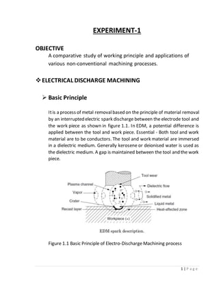
  • 1. 1 | P a g e EXPERIMENT-1 OBJECTIVE A comparative study of working principle and applications of various non-conventional machining processes. ELECTRICAL DISCHARGE MACHINING  Basic Principle Itis a process of metal removalbased on the principle of material removal by an interrupted electric spark discharge between the electrode tool and the work piece as shown in figure 1.1. In EDM, a potential difference is applied between the tool and work piece. Essential - Both tool and work material are to be conductors. The tool and work material are immersed in a dielectric medium. Generally kerosene or deionised water is used as the dielectric medium. A gap is maintained between the tool and the work piece. Figure 1.1 Basic Principle of Electro-Discharge Machining process
  • 2. 2 | P a g e Depending upon the applied potential difference (50to 450V) and the gap between the tool and work piece, an electric field would be established. Generally the tool is connected to the negative terminal (cathode) of the generator and the work piece is connected to positive terminal (anode).  Effect of process parameters on Material Removal Rate and Surface Roughness There are severalparameters which affect performanceof process. Some of them are given as below 1. Mean current 2. Frequency 3. Spark gap 4. Dielectric fluid supply 5. Pulse on time 6. Pulse off time  Meancurrent Figure 1.2 shows variation of MRR with mean Current across capacitor in relaxation circuit. Fromthe graph it can be seen that as mean current is increased MRR increases. Figure 1.2 Effect of mean current on material removal rate
  • 3. 3 | P a g e Two important process parameters in EDM are discharge current and frequency of discharges. As either of these parameters is increased, metal removal rate increases Surface roughness is also affected by currentand frequency, as shown in Figure1.3.Thebest surfacefinish is obtained in EDM by operating at high frequencies and low discharge currents. Figure 1.3 Effect of mean current on surface finish  Spark Gap A suitable gap is maintained between tool and work piece and is maintained by servomotor and it is actuated by comparing a reference voltage and gap breakdown voltagewhich feed tool downward toward work piece. As spark gap is increaseMRR increases up to highest value, which is optimum value. Then it starts decrease as shown in fig. 1.4 Figure 1.4 Effect of spark gap on MRR
  • 4. 4 | P a g e  Pulse on time The machining process becomes faster after increasing the pulse on time. By increasingthepulseon time the materialremovalrateincrease and poor surface finish on the material. Figure 1.5 shows the effect. Figure 1.5 Effect of Pulse on time on MRR Accordingto Influenceof InputParameterson theCharacteristicsof the EDM Process surfacefinish improves on increase in pulse on time. This result is shown in fig. 1.6 Figure 1.6 Effect of pulse on time on surface roughness
  • 5. 5 | P a g e  Applications 1. Drilling of micro-holes, thread cutting, helical profile milling, rotary forming, and curved hole drilling. 2. Delicate work piece like copper parts can be produced by EDM. 3. Can be applied to all electrically conducting metals and alloys irrespectiveof their melting points,hardness,toughness,orbrittleness. 4. Other applications: deep, small-dia holes using tungsten wire as tool, narrow slots, cooling holes in super alloy turbine blades, and various intricate shapes. 5. EDM can be economically employed for extremely hardened work piece. 6. Sincethere is no mechanical stresspresent(no physicalcontact), fragile and slender work places can be machined without distortion. 7. Hard and corrosion resistant surfaces, essentially needed for die making, can be developed  Advantages 1. Complex shapes that would otherwise be difficult to produce with conventional cutting tools. 2. Extremely hard material to very close tolerances. 3. Very small work pieces where conventional cutting tools may damage the part from excess cutting tool pressure. 4. There is no direct contact between tool and work piece. Therefore delicate sections and weak materials can be machined without any distortion. 5. A good surface finish can be obtained.  Limitations 1. The slow rate of material removal. 2. For economic production, diesurfacefinish specified should notbe too fine. 3. The additional time and cost used for creating electrodes for ram/sinlcer EDM.
  • 6. 6 | P a g e 4. Reproducing sharp comers on the work piece is difficult due to electrode wear. 5. Specific power consumption is very high. 6. Power consumption is high. 7. Overcut is formed. 8. Excessive tool wear occurs during machining. 9. Electrically non-conductive materials can be machined only with specific set-up of the process  ABRASIVE JET MACHINING  Basic Principle In abrasive jet machining (AJM) a focused stream of abrasive grains of Al2O3 or SiC carried by high-pressuregas or air at a high velocity is made to impinge on the work surface through a nozzle of 0.3- to 0.5-mm diameter. The process differs from sandblasting (SB) in that AJM has smaller diameter abrasives and a more finely controlled delivery system. The workpiece material is removed by the mechanical abrasion (MA) action of the high-velocity abrasiveparticles as shown in fig. 1.7. Thework material is removed by erosion by the high velocity abrasive particles. Figure 1.7 Basic scheme of Abrasive Jet Machining process
  • 7. 7 | P a g e Effect of Process Parameterson Material Removal Rate Process Parameters: 1. Abrasiveflow rate 2. Mixing ratio 3. Gas pressure 4. Velocity of fluid 5. Abrasivegrain size 6. Stand-off distance  Abrasiveparticle with small grain sizeis used to producesmooth and fine surface.  As mass flow rate of the gas in abrasivejet is increases, MRR first increases until an optimum value and then decrease. (a) (b) Figure 1.8 (a) Shows effect of Abrasive flow rate on MRR (b) Shows effect of mixing ratio on MRR  MRR increases with increasing in mixing ratio up to optimum value and then decrease.  MRR is directly proportionalto velocity of abrasiveparticle and gas pressure.  Ifthe densityof abrasiveparticleis gradually increased, theexit velocity will go on decreasing for the same pressure condition.
  • 8. 8 | P a g e  It is evident that the increased mass flow rate of abrasivewill result in decreased velocity of fluid and will thereby cause a decrease in available energy for erosion and ultimately the material removal rate. (c) (d) Figure 1.9 (c) Effect of Abrasive flow rate on MRR while constant mixing ratio (b) Effect of Gas Pressure on MRR Applications  Drilling holes, cutting slots, cleaning hard surfaces, deburring, polishing and radiusing  Deburring of cross holes, slots, and threads in small precision parts that require a burr-freefinish, such as hydraulic valves, aircraftfuel systems, and medical appliances  Machining intricate shapes or holes in sensitive, brittle, thin, or difficult-to-machine materials  Insulation stripping and wire cleaning without affecting the conductor  Micro-deburring of hypodermic needles  Frosting glass and trimming of circuit boards, hybrid circuitresistors, capacitors, silicon, and gallium  Removal of films and delicate cleaning of irregular surfaces because the abrasivestreamis able to follow contours  Advantage  Because AJM is a cool machining process, itis best suited for machining brittle and heat-sensitive materials like glass, quartz, sapphire, and ceramics.
  • 9. 9 | P a g e  The process is used for machining super alloys and refractory materials.  Itis not reactive with any workpiecematerial.  No tool changes are required.  Intricateparts of sharp corners can be machined.  The machined materials do not experience hardening.  No initial hole is required for starting the operation as required by wire EDM.  Material utilization is high.  Itcan machine thin materials.  Limitations  The removal rate is slow.  Stray cutting can’t be avoided (low accuracy of 0.1 mm).  The tapering effect may occur especially when drilling in metals.  The abrasivemay get impeded in the work surface.  Suitable dust-collecting systems should be provided.  Soft materials can’tbe machined by the process.  Silica dustmay be a health hazard.  Ordinary shop air should be filtered to remove moistureand oil ELECTRO-CHEMICAL MACHINIG  Basic Principle Electro-chemical machining (ECM) is an inherently versatile process of machining because of its capability of stress free machining of various kinds of metals and alloys. It can produce shapes and cavities which are costly and extremely difficult to machine with the conventional machining processes and a true replica of the tool (or cathode) can be made on the workpiece (or anode) by the controlled dissolution of the anode of an electrolytic cell. The basic scheme of the ECM process has been shown in Fig. 1.10, in which the tool serving as the cathode and the workpiece servingasthe anodeof an electrolytic cell havebeen shown.Anelectrolyte (usually a neutral salt solution such as sodium chloride, sodium nitrate,
  • 10. 10 | P a g e sodium chlorate) is passed through a very small gap (0.05 to 0.3 mm) created between the work- piece (or anode) and the tool (or cathode) whereas a direct current flow is made between them. Figure 1.10 Basic scheme of the ECM process When sufficient electrical energy (about 6 eV) is avail- able, a metallic ion may bepulled outof the workpiecesur-face. The positivemetallic ions will react with the negative ions present in the electrolytic solution forming metallic hydroxides and other compounds. Hence, the metal will be anodically dissoluted with the formation of sludges and precipitates. Figure 1.11 Schematic principle of Electro-Chemical Machining process
  • 11. 11 | P a g e  Effect of Process Parameters on Material Removal Rate and Surface roughness Process Parameters 1. Electrolyte concentration 2. Voltage 3. Feed rate 4. Electrolyte flow velocity  MRR is decrease with increasein the electrolyte concentration and surfaceroughness increaseup to certain level and then decrease. Figure 1.12 Effect of Electrolyte concentration on MRR and Surface Roughness  Surfaceroughness is increasewith increase in the voltage. MRR is increase with increase in voltage in somerang and then decrease. Figure 1.13 Effect of voltage on MRR and Surface Roughness
  • 12. 12 | P a g e  MRR and surfaceroughness decreases fastwith increasein feed rate up to certain value and then increase. Figure 1.14 Effect of Feed rate on MRR and Surface roughness  Application  ECM can be used for machining complicated profiles such as turbine wheels, turbine and jet engine blades, etc.  Machining of hard-to-machine and heat-resistant materials.  Drilling deep holes of small diameter as in nozzles.  Machining of cavities and holes of irregular shapes.  Advantage  There is no wear in the tool because there is no contact between the tool and the workpiece  Machining is done at low voltages, compared to other processes, with high metal removal rates.  Very small dimensions up to 0.05 mm can be controlled.  Complicated profiles can be machined easily in a single operation.  Becauseof the low temperature developed, no thermal damageoccurs to the workpiece structure.  Hard conductive materials can be machined.  The surface finish can be maintained at 0.1 to 1.25 μm Ra.  Because of its high capital cost, ECM is only suitable for mass production work  Labour requirements are low.
  • 13. 13 | P a g e  Limitations  A huge amount of energy is consumed (about 100 times that required for turning or drilling steel).  Metal removal rates are slow compared with conventional methods.  ECM can only be applied to electrically conductiveworkpiecematerials.  There are difficulties in safely removing and disposing of the explosive hydrogen gas generated during machining.  The workpiece needs to be cleaned and oiled immediately after machining.  There are difficulties with handling and containing the electrolyte, which may attack the equipment.  It is not easy to duplicate the shape of the tool electrode in the workpiecewith a high degreeof accuracybecauseof the sidemachining effect.  The process can’t produce sharp internal or external edges.  The pumping of high-pressure electrolyte into the narrow machining gap gives rise to large forces acting on the tool and the workpiece.  ELECTRON BEAM MACHINING Basic Principle Electron Beam Machining is process in which high velocity electrons are concentrated in a narrow beam and then directed towards the workpiece for machining. When this high velocity electron strikes the workpiece, it melts and vaporizes the material from the workpiece. In an electron beam machining, the electrons strike the workpiece with a high velocity. As the electron strikes the workpiece, the kinetic energy of the electron changes into heat energy. The heat energy so produced is used to melt and vaporizethe materials fromthe w/p. The whole process takes place in vacuum. Vacuum environment is used to prevent the contamination and avoid collision of electrons with air molecules. If the electrons collide with the air molecules, it will lost its Kinetic energy. Electron beamis generated in an electron beam gun. The constructionand
  • 14. 14 | P a g e working principleof the electron beam gun would be discussed in the next section. Electron beam gun provides high velocity electrons over a very small spot size. Electron Beam Machining is required to be carried out in vacuum. Otherwise the electrons would interact with the air molecules, thus they would loose their energy and cutting ability. Thus the workpiece to be machined is located under the electron beam and is kept under vacuum. The high-energy focused electron beam is made to impinge on the workpiece with a spot size of 10 – 100 μm. The kinetic energy of the high velocity electrons is converted to heat energy as the electrons strike the work material. Due to high power density instant melting and vaporisation starts and “melt – vaporisation” front gradually progresses, as shown in Fig. 1.15. Finally the molten material, if any at the top of the front, is expelled fromthe cutting zoneby the high vapour pressureatthe lower part. Unlike in Electron Beam Welding, the gun in EBM is used in pulsed mode. Holes can be drilled in thin sheets using a single pulse. For thicker plates, multiple pulses would be required. Electron beam can also be manoeuvredusingthe electromagnetic deflection coils fordrilling holes of any shape.
  • 15. 15 | P a g e Figure 1.15 Mechanism of material removal in Electron Beam Machining Application:  Electron Beam Machining is used to produce smaller size holes in various industries like automobile, aerospace, marine etc.  Drilling of holes in pressure differential devices used in Nuclear reactors, aircraft engines etc.  For removing small broken taps from holes.  For making turbine blades for supersonic Aero-engines. Advantages:  It can produce bolts of small sizes.  High accuracy and better surface finish.  Almost all types of materials can be machined.  Highly reactive metals such as Al and Mg can be machined easily.  As it does not apply any mechanical cutting forces on the workpiece, so cost of work holding and fixtures is reduced.
  • 16. 16 | P a g e  Reference list  Hassan El-Hofy, AdvanceMachining Process, TheMcGraw-HillCompanies, 2005  Bijoy Bhattacharyya, in Electrochemical Micromachining for Nanofabrication, MEMS and Nanotechnology, 2015  M. Rahman, ... M.D. Nguyen, in Comprehensive Materials Processing, 2014  McGeough, J.A.: Principles of electrochemical machining. 1974: Chapman and Hall
  • 17. 17 | P a g e EXPERIMENT-2 OBJECTIVE A comparative study of working principle and applications of various finishing processes. Importance of Finishing Processes  For many engineering applications, the finish on a surface can have a big effect on the performance and durability of parts. Rough surfaces generally wear more rapidly and have greater friction coefficients than smooth surfaces. Typically, roughness is a dependable predictor of mechanical part performance, as irregularities tend to formnucleation sites for breaks or corrosion.  Conversely, roughness may encourage desired adhesion. It provides a certain visual appeal.  Surface Finish is one of the most important factors when it comes to ordering material or following a specification. Due to the wide variety of effects different surfacefinishes can have, it should never be loosely defined or left up to interpretation. Theeasiest wayto achieve this is to identify surface finish via the standard industry designation or the proprietary designation. If at this point you are still thinking Surface Finish doesn’tmatter for my product, I would ask thatyou consider the following aspects that a finish can have only our material:  It can have a big effect on corrosion resistance.  It has different effects on certain manufacturing operations.  Different finishes require different economic considerations.  Itis important that once a particular SurfaceFinish is decided and then determined to work successfully for a manufacturer and their application, that all the metal they source has that exact finish every single time. This goes back to ensuring repeatability, consistency, and quality of the material you use to produce your products. Manufacturers and steel buyers should always work with your rolling partner to make surethat the metal you buy is produced the same way
  • 18. 18 | P a g e every time and superior quality and precision is maintained. This is crucial because finish can be affected by all of the following:  Cleanliness  Finish on the actual rolls  Supplier and supplier’s supplier  Thickness  Production route Graphical Symbols for Surface finish  Surface texture obtained by any manufacturing process (e.g., turning, grinding, plating, bending) except when bar or circle is specified. Figure 2.1 Basic symbolic for surface finish by any production process other than machining  Symbol indicating a surface requires a removal process and allowance indicated. Surface texture obtained by material removal by machining Operation (e.g., turning, drilling, Milling, slotting). The Horizontal bar indicates material removal by machining is required. Figure 2.2 Symbol for surface finish by any machining process
  • 19. 19 | P a g e  Symbol indicating a surface where removal processes are prohibited. The circle in the vee indicates the surfacemustbe produced by processes such as casting, forging, hot finishing, die casting etc. Figure 2.3 Symbol for surface finish without the removal of material Machining Symbol Figure 2.4 Machining symbol representation
  • 20. 20 | P a g e Auxiliary Symbols
  • 21. 21 | P a g e Roughness Grade Numbers and Ra Measures
  • 22. 22 | P a g e Instruments used for measurements of surface finishing 1. Profilometer A profilometer is a measuring instrument used to measure a surface's profile, in order to quantify its roughness. Critical dimensions as step, curvature, flatness are computed from the surface topography. There are two types of profilometers: stylus v/s optical. Stylus profilometers usea probeto detect the surface, physically moving a probe along the surface in order to acquire the surface height. Figure 2.5 Stylus Profilometer Figure 2.6 Optical Profilometer
  • 23. 23 | P a g e 2. Tomilmsonsurfacemeter Principle:Thisinstrumentusesmechanical-cum-opticalmeans for magnification. Construction: In this the diamond stylus on the surfacefinish recorder is held by spring pressure against the surface of a lapped cylinder. Figure 2.7 Schematic diagram of Tomilmsonsurfacemeter 3. Thetaylor-Hobsontalysurf The Talysurf is an electronic instrumentworking on carrier modulating principle. This instrumentalso gives the same information as the previous instrument, but much more rapidly and accurately. This instrument as also the previous one records the static displacement of the stylus and dynamic instrument like profilometer. The measuring head of this instrument consists of a diamond stylus of about 0.002mmtip radiusand skidor shoewhich is drawnacrossthe surfaceby means of a motorized driving unit (gearbox), which provides three motorized speeds giving respectively x20, and x100 horizontal magnification and a speed suitable for average reading.
  • 24. 24 | P a g e A neutral position in which the pick-up can be traversed manually is also provided. In this casethearm carrying thestylus forms an armaturewhich pivots about the centre piece of E-shaped stamping. On two legs of (outer pole pieces) the J5-shaped stamping there are coils carrying an a.c. current. These two coils with other two resistances form an oscillator. As the armature is pivoted about the central leg, any movement of the stylus causes the air gap to vary and thus the amplitude of the original a.c. current flowing in the coils is modulated. The output of the bridge thus consists of modulation only as shown in Fig. 2.8. Figure 2.8 Schematic diagram of Thetaylor-Hobsontalysurf MAGNETICFIELD ASSISTED POLISHING Magnetic field assisted Polishing” is essentially the manipulation of a homogeneous mixture of magnetic particles and abrasive particles with a magnetic field to impart a machining force on a workpiece.
  • 25. 25 | P a g e Relative motion between the particle mixture and the workpiece surface result in material removal. Since MFAP does not require direct contact with the tool, the particles can be introduced into areas which arehard to reach by conventional techniques. Figure 2.9 Schematic scheme of Magnetic field assisted polishing process using mc slurry Additionally carefulselection of magnetic particles and abrasiveparticles give rise to surfacetexture and roughness control that was previously impossible especially for hard to access are:  Process parameters of magnetic fieldassistedpolishing influencing MRR 1. Pressure during machining 1. Time taken by the process 2. Rotational speed of work piece 3. Reciprocating velocity of the MR fluid 4. Working gap between electromagnet poles.  Process parameters of magnetic field assisted polishing influencing surface roughness
  • 26. 26 | P a g e 1. Amount of abrasive particles 2. Feed speed, 3. Finishing gap HONING Honing is a type of abrasiveprocess typically used to finish the interior of a cylinder. Rather than using an abrasive wheel as in grinding, a hone uses severalflat stones arranged around a mandrel that moves in and out of the hole. For vertical or horizontal honing, the tool reciprocates through the hole, while in a single-pass finishing systemthere may be an indexing table with tools of expanding width that each movethrough the hole once. Either way, the process is the same. Because honing is a slower process than grinding, heat and pressures are lower. This means that honing provides better size and geometry control. Hones are incredibly accurate and can finish a part to within 0.2 microns (the width of a bacterium). In fact, single-pass hones are so consistent and so accurate that they are usually not gaged. While honing may take longer than somegrinding operations, it can also be done unattended. Single-pass hones tipped with diamond or CBN have incredibly long tool life.  Process parameters influencing surface roughness 1. Cutting Speed 2. Specific pressure  Process parameters influencing material removal rate 1. Honing speed 2. specific honing pressure 3. Feed 4. Depth of cut
  • 27. 27 | P a g e REFERENCES [1] MC. Malburg, J. Raja, DJ. Whitehouse, Characterization of Surface Texture Generated by Plateau Honing Process, CIRP Annals - Manufacturing Technology, 42 (1993) pp. 637-639 [2] https://isofinishing.com/surface-roughness-symbols [3]https://scholar.google.co.in/scholar?q=process+parameters+that+effect+o n+MRR+of+magnetic+assisted+polishing&hl=en&as_sdt=0&as_vis=1&oi=scho lart [4] https://www.eng-tips.com/viewthread.cfm?qid=464641
  • 28. 28 | P a g e EXPERIMENT-3 OBJECTIVE Evaluation effects process parameter in Metal forming processes. EXPLOSIVE FORMING PROCESS  Explosive forming is distinguished from conventional forming in that the punch or diaphragm is replaced by an explosive charge. Explosives used are generally high explosive chemicals, gaseous mixtures, or propellants.  Inexplosiveformingprocessan explosivechargeis detonated. High energy is produced and as a result of which the metal is given a very rapid acceleration overa veryshortperiod of time and is formedinto a die shape mainly as a result of kinetic energy. This process I normally used for the forming of flat sheet or plate into a form die. Tubes may also be bulged explosive.  Basic Principle  The principle of explosive forming process is shown in fig 3.1
  • 29. 29 | P a g e Figure 3.1 Basic scheme of explosive forming process
  • 30. 30 | P a g e  Sheet metal work piece blank is clamped over a die and the assembly is lowered into a tank filled with water. Air in the die is pumped out. Explosive chargeis placed at some predetermined distance fromthe work piece. On detonation of the explosive, a pressure pulse of very high intensity is produced. Gas bubble is also produced which expands spherically and then collapse.  The charge is placed at some distance from the sheet metal blank and is immersed in a transmitting medium usually water. When explosive is ignited the energy released forces the metal into the die to take the required shape. In free forming stretching of the blank takes place and deformation of the work piece depends on its ability to get stretched. This method is generally used to produce shallow components.  Explosive forming, is distinguished from conventional forming in that the punch or diaphragm is replaced by an explosive charge. Explosives used are generally high explosive chemicals, gaseous mixtures, or propellants. Effect of Process Parameters There are many process parameters: 1. Type and amountof explosive: wide range of explosive available. 2. Standoff distance- SOD (Distancebetween work piece and explosive): optimum SOD mustbe maintained. 3. The medium used to transmit: water is most widely used. 4. Work material properties. 5. Vacuumin the die. 6. Energy transfer medium. 7. Pressurepulse. 8. Strain and energy.
  • 31. 31 | P a g e Factor affecting Process parameters Pressure pulse:  In an underwater stand-off operation where the energy is released by detonating explosivecharge the intensity spherically expanding pressure pulse is initiated when travels outward through water at a velocity of about 1640 meter per second.  The pressure pulse generated by a detonating charge will propagate outward through the water with an expanding spherical front, constantly reducing in peak pressure and unit impulse due to energy losses to the water and the divergent nature of the pulse. Figure 3.2 showing relationship between time vs. pressure  At an given distance from the centre of the charge, the pulse will have a pressuretime profile of the type shown in fig. 3.2. Peak pressure, impulse and energy associated with the pressure pulse are given by the following expressions 𝑝𝑚= Peak pressure=A (W1/3 ) 𝐼 = 𝐼𝑚𝑝𝑢𝑙𝑠𝑒 = 𝐵𝑊1/3 [ 𝑊1/3 𝑅 ]  E=Energy flux passing through a unit area of a fixed surface lying normal to thedirection of propagation of the wave. 𝐸 = 𝐶𝑊1/3 [ 𝑊1/3 𝑅 ]  Where values of constantA, B, C, α, β and γ depend on type of explosive
  • 32. 32 | P a g e Strainand Energy  The amount energy that can be absorbed by the deforming material indicates its toughness which is its capacity to withstand shock loading without fracture. It is observedthat below a certain critical impact speed both the strain and energy to fracture in case of many steels is not greatly affected by strain rate. (a) (b) Figure 3.3 (a) Shows strain distribution on the blank being deformed by shock waveenergy sourceforming methods like: (i) high explosiveforming operation, (ii) electron-hydraulic forming operation. (b) Shows strain variation for the following metal forming processes: (i) Hydraulicpress operation. (ii) Stretch forming Energy transfer medium  The energy transfer medium should be properly selected. The choice of medium such as water or air transmitting the pressurepulse between the explosive and the work piece is normally limited form practical consideration.Becauseair is verymuch compressiblethan water the shock pressure produced are very much lower.
  • 33. 33 | P a g e Peak pressure vs. Standoff distance Figure 3.4 shows the variation of peak pressure (p) at the workpiece as a function of stand-off distance(s) for water and air.  ELECTRO-HYDRAULIC FORMING The principle used in electro-hydraulic forming can be stated as the ability to generate high-intensity shock waves submerged in a liquid medium. Figure 3.5 Schematic diagram of Electro0hydraulic forming process As shown in fig.3.5 illustrates of an electro-hydraulic forming systemfor a tubular part. It uses two electrodes which are connected via a switch to a bank capacitors. The electrode ends may be connected by a thin initiating wire which is vaporized during the discharge. As shown in Fig. The work- piece is immersed in water together with electrodes which are connected via a switch to a bank capacitors. Thecapacitors arecharged froma power
  • 34. 34 | P a g e unit through a charging resistor to a predetermined voltage and energy level. When the switch connecting the capacitors to the electrodes is closed, the stored energy is discharged across the gap at the ends of the electrodes. The electrical energyis converted into shockwavein the water which forms work-piece into die. Effect of Process Parameters  Electrode gap The gap between electrodes depends mainly upon charge voltage. Figure 3.5 shows the relationship between Deformation vs. Gap width Optimum gap width affects: (i) Deformation of work-piece. (ii) Process efficiency Gap width also depends on conductivity of water.  Stand-off distance Itis the distance fromthe spark gap to the work-piecefig. shows variation of central deformation with stand-off operation.
  • 35. 35 | P a g e Small stand-off distanceareused to produceconically shaped freeformed components because of the concentration of energy at the centre of the blank. Figure 3.6 Stand-off distance vs. Central displacement  Hydrostatic head Itis the verticaldistancebetween thesparkgapand surfaceof water.Since the majority of electro-hydraulic forming operation take place in completely closed containers, hydro-static head has no relevance, but in installation where there is a free water surface, it has a considerable influence on the amount of deformation produced as shown in fig.3.7. Figure 3.7 Hydrostatic head vs. Central displacement
  • 36. 36 | P a g e ELECTROMAGNETIC FORMING  Basic Principle To illustrate the principle of electromagnetic forming, consider a tubular work piece. This work piece is placed in or near a coil, a high charging voltage is supplied for a short time to a bank of capacitors connected in parallel. (The amount of electrical energy stored in the bank can be increased either by adding capacitors to the bank or by increasing the voltage). When the charging is complete, which takes very little time, a high voltage switch triggers thestored electrical energy through the coil. A high intensity magnetic field is established which induces eddy currents into the conductive work piece, resulting in the establishment of another magnetic field. The forces produced by the two magnetic fields oppose each other with the consequence that there is a repelling force between the coil and the tubular work piecethat causes permanentdeformation of the work piece. Figure 3.8 shows the circuit diagram for EMF system: Figure 3.8 Equivalent circuit diagrams: a) detailed version b) reduced version Magnetic forming can be accomplished in any of the following three ways, depending upon the requirements:
  • 37. 37 | P a g e  Electromagnetic Compression Figure 3.9 Application of magnetic forming process: Swaging Coil surroundingworkpiece.When a tube – like partx is to fitover another part y (shown as insert in Fig 3.9, coil is designed to surround x so that when energized, would force the material of x tightly around y to obtain necessary fit.  Electromagnetic Expansion Figure 3.10 Application of magnetic forming process: Expanding Coil inside work piece. Consider fixing of a collar on a tube – like part, as shown in Fig 3.10. Themagnetic coil is placed insidethe tube – like part, so that when energized would expand the material of the part into the collar.
  • 38. 38 | P a g e  Sheet Metal Forming Figure 3.11 Application of magnetic forming process: Embossing or blanking Coil on flat surface. Flat coil having spiral shaped winding can also be designed to be placed either above or below a flat work piece, see Fig (4). These coils are used in conjunction with a die to form, emboss, blank, or dimple the work piece. Effect of Process Parameters a. Die Material:  The die used in MPF should be made of low electrical conductivity to minimize the magnetic cushion effect. Dies are generally made of the following materials, (i)Steel (ii)Epoxy Resin  Steel dies have longer life. But the disadvantage of steel dies is that magnetic cushion effect is not entirely prevented. b. Coils:  Coil through which the stored energy is discharged should be designed properly. Coils should be designed in such a way that stray inductance is minimized and current concentrations are avoided.
  • 39. 39 | P a g e  High permeability material cannotbeusedbecauseof thehigh fluxdensities required, which may be up to 300 kilo-gauss. The coil is usually made of copper tubing, so that it can be cooled to increases the coil life. There are two types of coil: (i)Expandable (ii)Permanent  Expandable coils made from a few turns of copper wire. These coils are cheap and can be used only once, as they arevaporizedby the large current flowing upon discharging the capacitors.  A permanent coil must be rigidly supported so that it is not deflected or distorted by the interacting forces between it and the work piece. Fig 3.12 central deflection vs. coil spacing  The central deflection of the work piece gets reduced if the spacing between the turns ofcoil is increased as shown in fig.3.12 c. Energy:  Magnetic forming is used to shape and assembled light component, mainly from thinsheet or tube. The upper limit of energy released through a coil is ultimately determined by the maximum size of capacitor available. Unit up to 500 kJ have been built, but 100kJ is a more practical upper limit that can be easily generated.
  • 40. 40 | P a g e Fig. 3.13 central deflection vs. energy  The central deflection of the work piece varies with energy released as shown in fig.3.13. Some important features of electromagnetic forming: Some important characteristic process features that make the electromagnetic forming different from other forming processes are: 1) Sheet metal in electromagnetic forming must be conductive enough to allow the sufficient induced eddy currents. The efficiency of electromagnetic formingis directly related to the conductivity of the metal sheet. Metals with poor conductivity can only be formed effectively if an auxiliary driver sheet with high conductivity is used to push the metal sheet. Aluminium alloys are good electrical conductors with higher conductivity compared to plain carbon steel. Aluminium alloys are generally suitable for electromagnetic forming. 2) The dischargetime of electromagnetic formingis very short,generally very short in the order of 10 microseconds. The conventional sheet stamping usually takes a few seconds. The current in coil and sheet metal are damped sinusoidally, and the most deformation work is done within the first half cycle. Therefore, electromagnetic forming is a transient event compared with conventional sheet stamping.
  • 41. 41 | P a g e 3) As mentioned before, the distribution of electromagnetic pressurecan be directly controlled by the spatial configuration of the coil. The magnitude of electromagnetic pressurecan be controlled by the stored chargein the capacitor bank. Advantages of magnetic pulse forming: Magnetic pulse forming offers a number of advantages with regard to other deformation techniques: 1) Reproducibility: Since the electric energy in the coils can be controlled very precisely, the reproducibility is very high. 2) Without contact: In contrast to traditional deformation techniques, the magnetic fields generate the forces. No lubrication is necessary and since this technique operates without contact, the damage which can be caused by a former in the conventional method can be avoided. Surface treated materials (e.g., anodising) can be formed, without damaging the surface layer. 3) Spring-back: The material is deformed plastically, resulting in a permanent plastic deformation, where spring-back of the deformed material is avoided. 4) The process ensures a higher formability of the workpieces due to the lower internal stress and friction, in comparison with other mechanical forming processes. Workpieces which must be stress-relieved in conventional forming processes, can be formed with magnetic pulse forming in a single step.
  • 42. 42 | P a g e Applications: Electromagnetic forming process is capable of a wide variety of forming and assembly operations. Ithas found extensive applications in the fabrication of hollow, non – circular, or asymmetrical shapes from tubular stock. The compression applications involve swaging to produce compression, tensile, and torquejoints or sealed pressurejoints,and swagingto apply compression bands or shrink rings for fastening components together. Flat coils havebeen used on flat sheets to produce stretch (internal) and shrink (external) flanges on ring and disc – shaped work pieces. Automotive industry:  Drive shafts  Components of air conditioning  Fuel filters  Closing caps of cylindrical components  Coatings of exhaust systems  Forming and perforating aluminium tubes (e.g., for car seats) Electrical sector:  Electric fuses  Components of electric motors  Cable ducts HVAC - industry: Heating, Ventilating, and air Conditioning:  Components of cooling units, air conditioning, cooling tubes (as a replacement of e.g., brazing or mechanical joining techniques)
  • 43. 43 | P a g e REFERENCES (1) G.S.Nagpal “Metal Forming Process”, ch-8 explosive forming process, pg. no.-258-275. (2) G.S.Nagpal “Metal Forming Process”, ch-9 electro-Hydraulic forming process, pg.no.-286-292. (3) G.S.Nagpal “Metal Forming Process”, ch-10 electro-Magnetic forming process, pg.no.-297-303. (4) V. Psyk, D. Risch, B.L. Kinsey, A.E. Tekkaya, M. Kleiner, “Electromagnetic forming—A review” Journal of Materials Processing Technology 211 (2011) 787–829. (5) NPTEL – Manufacturing Process I - Link (6) Dhiraj Gayakwada, Mahesh Kumar Dargara, Pramod Kumar Sharmaa, Rajesh purohit,R.S.Ranab.“A Review on Electromagnetic FormingProcess”,Procedia Materials Science 6 (2014) 520 – 527
  • 44. 44 | P a g e EXPERIMENT – 4 OBJECTIVE: A comparative study of working principle and application of various micro- machining processes and study effect of process parameters of them. Needs of Micromachining Nowadays, focus is on miniaturization through development of novel production concept (especially Micro & Nano), so there is trends towards the new technologies with reduction in dimensions with more functionality. Micromachining is the most basic technology for the production of micro parts and components with micro tools. Micromachining is capable of producing parts up to the micrometer range (1–999 μm). This reduces lead time and allows parts to be machined more efficiently. This reduces the energy and material used of the manufacturing. This minimizes the overall power consumption and total cost. This gives us good accuracy as compareto other processes. This leads to faster production and reliability. Micromachining removes the material at micro level which reduces the unwanted material. It is also gives better surface finishing with minimum tolerances. As this process is accurate and trustworthy, it has becoming an increasingly popular choice for many industries Importance of Micromachining Micromachining process is flexible as compare to non-conventional process. The main benefit of Micromachining using specialized techniques and tools is that it allows the reliably repeatable as efficient production of small and intricate parts that have tight tolerances. It can produce 3D components as well as complex. It produces a part with detail. Importanceof this processes is that all factors which are affected is minimized and makes more reliability than other manufacturing processes. Precise positioning and machining accuracy along with CAD/CAM software enable the micro-EDM machine to produce complex shapes with a high degree of precision. The reality that micro-EDM is a non-contact process makes high precision machining on curved surfaces, inclined surfaces, and very thin sheet materials possible.
  • 45. 45 | P a g e MICRO-ELECTRICAL DISCHARGE MACHINING  Basic Principle: Sameprinciple of EDMis applied at the micro meter level for micro machining and the processwascalled asmicro-EDM.IncaseofconventionalEDM, higher energy resulted in a higher removalratebut a roughersurface.Inmicro-EDM, the key aspect is to limit the energy discharge in the order of micro-Joule at higher frequency. Depending upon the applied voltage and the gap between the tool and work piece, an electric field would be established. Voltage applied to create an electric field higher than the dielectric rigidity of the fluid. When two electrodes is estranged by a dielectric medium that is at first non-conductive breaks down and becomes conductive. In between this period sparks will be generated between the electrodes. The thermal energy released will be used to removematerial by melting and evaporation.At firsta high voltagecurrent is necessary to discharge in order to rise above the dielectric breakdown strength of the small inter electrode gap formed between the electrodes is a channel of plasma (electrically conductive and ionized gas with temperature of very high) and its further development depends upon the discharge durations. Electrical resistance of such plasma channel would be very less. Then suddenly, a huge number of electrons will startflowing from the tool to the job and ions from the job to the tool this type of motion of electron is called avalanche motion of electrons. This movement of ions and electrons are shown as spark. Then these high speed electrons are strikes on the job and ions on the tool, and create a localized heat flux. Such severe contained heat fluxleads to extreme instantaneousrestrained risein temperaturewhich would be in excess of 10,0000C. Becauseof such instancerisein temperature it leads to material removal. Mechanism of Micro-EDM is shown in fig. 4.1. Material removed because of the immediate vaporization of the material as well as due to melting. The molten metal is removed only partially. As the potential differencehas introverted the plasma channelcollapse, it generates pressureor shock waves, because of this a crater is formed by molten metal around the spark. An importantpointof micro-EDMis the inverted polarity of the tool electrode. Ithas been used shortpulse durations. Therefore the tool electrode is usually charged as cathode.
  • 46. 46 | P a g e Figure 4.1. The model of breakdown stage. (a) Secretion of pre breakdown current and heating at micro peaks. (b) The nucleation of bubbles at micro- peak. (c) At the bubble interface electron impact criteria is reached. (d) Elongation of the bubbles towards anode. (e) Bubble reduced the gap between the electrodes and plasma channel at the end of the breakdown phase.  Effect of Process Parameters on Material Removal Rate: 1. Voltage Material removal rate is inversely proportional to the voltage. MRR is lower on increasing of voltage. The possible reason for the decrease in MRR at high gap voltages is decreased gap current. 2. Pulse on time It can be inferred of fromthe graphs, the material removal rate increases proportionally with increasing pulse on time. The reason for the increased MRR is due to the increased spark energy as the pulse on time increases. The maximum MRR was obtained at high level of pulse on time.
  • 47. 47 | P a g e 3. Pulse off time During pulseoff time there is no material removal, however thereason for increased MRR is attributed to better flushing of micro debris during long pause time which results in improved MRR. The maximum MRR was obtained at high level of pulse off time. Figure 4.2 Shows the Effect of process parameters on Material removal rate 4. Current Current is directly proportional to the material removal rate. Material removal rate is increases with increases in current. Fig 4.3 Shows the Effect of current on MRR
  • 48. 48 | P a g e MICRO TURNING  Basic Principle: Itis a conventional material removal process that has been miniaturized. For carrying out the process of cutting, the workpieceand the cutting tool must be moved relative to each other in order to separate the excess layer of material in the form of chips. Fig. 4 illustrates the concept of micro turning. Fig 4.4 Machining Process of Micro turning The relative motion is required between the tool and work to perform a machining operation. The primary motion is accomplished at a certain cutting speed. Inaddition, thetool mustbemoved laterally acrosstheworkat a much slower motion, called the feed. The remaining dimension of the cut is the penetration of the cutting tool below the original work surface, called the depth of cut. Collectively, speed, feed, and depth of cut are called the cutting conditions. The predominant cutting action in machining involves shear deformation of the work material to form a chip; as the chip is removed, a new surface is exposed as shown in Fig. 5.
  • 49. 49 | P a g e Fig 4.5 Cross section view of machining process of micro turning  Effect of Process Parameters on Material Removal Rate: 1. Cutting Speed Material removal rateincreases with increases in cutting speed. As cutting speed increases, it decreases the machining time thus it will increases the MRR. 2. Feed Rate In micro turning material removal rate is increases with increase in feed rate because of high feed rate increases the contact of area of tool and workpiece. 3. Depth of Cut Material removal rate is increases with increases in the depth of cut. It increasesthecutting force.Becauseof increasesin depth of cutit increases the removal of material, hence MRR is increased.
  • 50. 50 | P a g e Fig 4.6 Shows the Effect of Process Parameters on Material Removal Rate HYBRID MICROMACHINING Hybrid micro-machining Method is define as the combination of machining operations by which two or more machining processes are applied independently on a single machine, or in terms of an assisted machining approach,bywhich two ormoreprocessesareutilized simultaneously. Hybrid micro-machining processes which involve integration of various micro- machining processes with the purpose of improving machinability, geometrical accuracy, tool life, surfaceintegrity, machining rate and reducing the process forces. Hybrid micro-machining processes are classified in two major categories namely, assisted and combined hybrid micro-machining techniques. Some hybrid micro-machining processes havebeen approved to be able to improve machinability of hard-to-machine materials, tool life, geometrical accuracy, surface integrity and machining efficiency.
  • 51. 51 | P a g e Fig 4.7 Classification of Hybrid Micro Machining Process  ASSISTED HYBRID MICRO MACHINING External electric field-assisted micro-machining Introducing an electric field during micro-machining can assist to remove debris and prevent particles fromredepositing onto the surface. A schematic of the experimental setup for external electric field-assisted femtosecond laser micro-machining and the device for providing an external electric field are presented in Fig. 4.8. Material removal with the femtosecond laser is a complex process. At femtosecond time scale, free electrons absorb laser energy and leave the sample surface in several picoseconds. The ultrashort laser pulses with mJ- pulse energy produce sufficiently high peak power that leads to ionization of the substrate material and therefore formation of the plasma. The presence of the plasma can lead to a large number of
  • 52. 52 | P a g e micro/nano-sized particles being deposited on the substrate surface .By introducing an electric field during the fs laser machining, redeposition of particles onto the surface can be inhibited. For the charged particles to be removed by the electric force, the particle weight needs to be smaller than the electric forces. When an external electric field is applied duringthe femtosecond laser micro- machining of silicon, a significantly improved machined surface quality with much reduced amount of surface contaminants is achieved, as depicted in Figure 4.9. Figure 4.8 (a) Schematic of the experimental setup for external electric field- assisted laser micro-machining (b) Device for providing an external electric field (a) (b) Figure4.9 Fs laser micro-machining of silicon a) withoutthe external electric field. b) With the external electric field
  • 53. 53 | P a g e  COMBINED HYBRID MICRO MACHININIG  Micro-ECM and micro-mechanicalgrinding Hybrid process of electrochemical material removal and mechanical grinding for machining of precision small holes was established. As demonstrated in Fig. 4.10, a spherical metal rod with coated diamond abrasives as cathode tool rotates at high speed and removes material electrochemically and mechanically for a pre-machined pilot hole. The pilot hole with diameter of D0, which is smaller than the final hole diameter D1. Itis essential that the tool core is electrically conductive and the abrasiveis electrically non-conductive. During the machining process, the tool is charged negatively and the workpiece performs as the anode. The abrasiveparticles (diamond particles) in the tool protrudebeyond the conductive bond surface (nickel layer). This establishes a small gap between the tool nickel layer and hole side wall. In the proposed process, workpiecematerial removaloccurs in two phases, as indicated in Fig 4.10. Electrolytic action begins when the gap is filled with an electrolyte and the tool is electrically charged. Phase 1 is entirely electrochemical action. In this phase, passivation film occurs on the hole surface because passive electrolyte NaNO3 is used. Phase 2 is a combination of electrochemical action and mechanical grinding. As the abrasive tool feeding down, the gap decreases until the abrasives on the tool base comes into contact with the workpiece. The abrasivegrains actto removethe soft, non-reactivepassivation layer, thus exposing fresh metal for electrolytic reaction. Simultaneously, the electrolyte trapped between the protruding abrasive grains and the workpieceforms tiny electrolytic cells, thus electrochemical dissolution of workpiece materials occurs. So in phase 2 material is removed from the workpiece surface by both electrochemical dissolution and mechanical abrasive grinding. Phase 2 ends at the point where the maximum tool diameter is. For obtaining sharp edges and high dimensional accuracy of hole, the tool should be insulated except the first half of the sphere. So, there is no removal action taking place in phase 3.
  • 54. 54 | P a g e Ifthe toolis not insulated, the electrochemical dissolutionwill continuefor the machined hole surface (phase 3) because of the electrical field between the machined hole surfaceand the tool, resulting in a taper hole. The finest surfacefinish of 0.21 μm can be obtained in stainless steel 321 work material. Figure4.10 Schematic view of the proposed hybrid process pf electrochemical removaland grinding REFERENCES [1] M. Siva, M. Parivallal, M. Pradip Kumar, “Investigation on the effect og process parameters in micro electrical discharge machining”, Procedia Material Science 5 (2014) 1829-1836 [2] Skandesh B.L, K.M Mathew, R Oyyaravelu, P Kuppan, “Effect of Process Parameters on Material Removal Rate in μ-EDM of Magnesium Nano-Composite” International Research Journal of Engineering and Technology (IRJET) Volume: 03 Issue: 09 | Sep-2016
  • 55. 55 | P a g e [3] V. Senthilkumar, S. Muruganandam, “State of the Art of Micro turning Process”, International Journal of Emerging Technology and Advanced Engineering, Volume 2, Issue 1, February 2012 [4] C. Mgbemena, C. Mgbemena, G. Etebenumeh and F. Ashiedu, “EFFECT OF TURNING PARAMETERS ON METAL REMOVAL AND TOOL WEAR RATES OF AISI 1018 LOW CARBON STEEL”,Nigerian Journal of Technology (NIJOTECH),Vol. 35, No. 4, October 2016, pp. 847 – 854 [5] Saeed Zare Chavoshi, Xichun Luo, “Hybrid Micro-machining Processes: A Review”, Centre for Precision Manufacturing, Department of Design, Manufacture and Engineering Management, University of Strathclyde, Glasgow, G1 1XJ, UK
  • 56. 56 | P a g e EXPERIMENT-5 OBJECTIVE STUDY OF PROCESS PARAMETERS OF LASER PROCESSING.  Introduction to Laser LASER is the acronym for Light Amplified Stimulated Emission of Radiation. Emits light through a process of opticalamplification based on the stimulated emission of electromagnetic radiation.  Principle of laser The word laser is an acronym for Light Amplification by the Stimulated Emission of Radiation. When an atom absorbs a quantum of energy from a light source, the orbital electron of an atom jumps to a higher energy level. The electron later drops to its original orbit and emits the absorbed energy. If the electron, which is already at high energy level, absorbs the second quantum of energy, it emits two quanta of energy and after emitting the energy it returns back to its original orbit. The energy that is radiated has the same wave length as the simulating energy. The laser material when placed in an optical cavity and exposed to light energy keeps storing the energy. The energy initially builds up in the laser material and finally gets emitted in the formof a highly amplified light beam. Thebasic mechanismof energy transfer in laser beam is shown in Figure and laser beam generation is schematically shown in Figure 5.1. Figure 5.1 Mechanism of energy transfer in laser beam
  • 57. 57 | P a g e  TYPES OF LASERS Solid state lasers have lasing material distributed in a solid matrix, e.g., the ruby or neodymium-YAG (yttriumaluminium garnet) lasers. Theneodymium- YAG laser emits infrared light at 1.064 micrometres. Gas lasers (heliumand helium-neon, HeNe, are the mostcommon gas lasers) have a primary outputof a visible red light. CO2 lasers emit energy in the far- infrared, 10.6 micrometres, and are used for cutting hard materials. Excimer lasers (the name is derived from the terms excited and dimers) use reactive gases such as chlorine and fluorine mixed with inert gases such as argon, krypton, or xenon. When electrically stimulated, a pseudo molecule or dimer is produced and when lased, produces light in the ultraviolet range. Dye lasers use complex organic dyes like rhodamine 6G in liquid solution or suspension as lasing media. They are tenable over a broad range of wavelengths. Semiconductor lasers, sometimes called diode lasers, are not solid-state lasers. These electronic devices are generally very small and use low power. They may be built into larger arrays, e.g., the writing source in some laser printers or compact disk player.  LASER CUTTING  Introduction to Laser Cutting Laser cutting is a technology that uses a laser to cut materials, and is typically used for industrial manufacturing applications. Cutting is similar to drilling - the beam is simply moves along the material, or vice versa. For non-reflective materials (wood,plastic,cloth) this worksdirectlybutif the surfacesareshiny, often oxygen is blown overthe surfacenear the focusedbeamand the oxygen is used to burn away the metal in a process known as laser-assisted cutting.
  • 58. 58 | P a g e CO2 lasers are used for industrial cutting of many materials including mild steel, aluminium, stainless steel, titanium, paper, wax, plastics, wood, and fabrics. NeodymiumYttrium-Aluminium-Garnet(Nd-YAG) lasers areprimarily used for cutting and scribing metals and ceramics. Figure 5.2 Basic principle of laser cutting  Process parameters of Laser Cutting In order to execute the operation of laser cutting it is necessary to know the processing parameters. Processing parameters include the characteristics of the laser cutting process that can be modified to improve the quality of the cutting processand achievethe required results of cutting. The parameters of the laser cutting processcan be classifiedinto fourmajor categories: specified parameters of laser cutting, input parameters of laser cutting, operating parameters of laser cutting and output parameters of laser cutting. The specified parameters of laser cutting are: gas type, gas purity, gas pressure, the diameter and shape of the nozzle. Gas pressureand the shape of the nozzle havean effect on the roughness of the cut. The consumption of cutting gas depends on gas pressure and diameter of the nozzle. Cutting by low pressuregas requires the pressureof up to 5bars, whereas in cutting by high pressuregas, the pressurecan reach 20 bars. Conventionalnozzles have a circular, conical opening. The distance between the nozzleopening and the surface of the work piece must be as small as possible. The smaller the
  • 59. 59 | P a g e distance, the greater the amount of gas that enters the cut. The gap width usually ranges from 0.5 to 1.5 mm. Operating parameters of laser cutting with which the quality of cutting can be optimized are: focus position, laser power, gas pressure, feed rateand the distance between the nozzle and the cutting surface. Original cutting parameters are optimized to ensuremaximum reliability of the process. Each laser is supplied with a set of cutting parameters. Cutting parameters are given for the materials of specific type and thickness. For materials for which the laser manufacturerdid not providethe recommended values,new cutting parameters could be set. Effect of process parameters on Laser Cutting Laser power is a parameter that defines the power of the laser during continuous operating mode of the laser (cw-continuous wave). It should be noted that there is a difference between continuous wave and pulse wave.Incontinuous operating mode, thenominalpower of the laserbeam is continuously available, while in pulse operating mode it is emitted at intervals. Gas pressure depends on the cutting gas and the nozzle used. In oxygen (O2) assisted cutting, the higher value results in higher cutting temperature and rougher shape of the cut. With the use of nitrogen (N2) and compressed air, the material is ejected and cooled more easily. In cutting with O2 the maximum gas pressureis 10 bars, in cutting with N2 the maximum gas pressureis 24 bars, whereas in cutting with compressed air the maximum pressure is 12 bar. Feed rateis a parameter that defines the cutting speed during continuous operating mode of the laser (cw). Feed rate is a variable which is dependent on other factors. It should be noted that the reduction of the feed rate by 10 - 20% leads to significant improvement of quality and process reliability in almost all cases.
  • 60. 60 | P a g e Nozzle distance is a parameter that defines the distance between the nozzle and the surfaceof the work piece during the cutting process. This distanceaffects the flow of gas,which furtherhas a directeffect on cutting performances and cutting quality. If the nozzle distance is larger than 1 mm, significant variations in pressurewill occur. It is recommended that the nozzle distance be smaller than the diameter of the nozzle, because greater distance can result in turbulence and considerable changes in pressure in the gap between the nozzle and the work piece.  LASER SURFACE MODIFICATION TECHNIQUE  Requirement for Laser surface modification  Enhanced mechanical properties: hardness/fatigue  Enhanced corrosion resistance  Enhanced tribological properties: wear/abrasive  Enhanced electrical/electronic  Enhanced aesthetic look  Enhanced thermal/heat resistance properties  Enhanced machinability of fabricability Laser surface modification uses intense thermal energy of laser beam for modification, alloying and cladding surface of substrate material. In this technique veryhigh cooling rates can beachieved whicharreststhepossibility of segregation in multicomponent system. More over very narrow heat affected zone and easy automation makes it suitable for large scale industrial production. This method depends on many process parameters such as  Laser power  Scan speed  Focal length  Spot size  Substrate material  Surface temperature
  • 61. 61 | P a g e Selection of proper range of process parameters for good surface quality is essential. Pores and cracks may arise due to improper selection of parameters. Multi-layered, high-entropy, thermalbarrier coatings using laser surface modelling with good bonding with substrates have been developed.  Principle When a laser is incident on a substratematerial, laser radiations areabsorbed by conduction electrons near the surfaceregion (in nm range). These excited electrons collide with lattice ions and rapidly produce heat. The heat producedin this thin layeris conducted to the bulksubstrate.This causesswift heating of a layer of material, having a thickness greater than the characteristic radiation absorption depth. As soon as the laser irradiation is stopped, the substratematerial cools due to heat transfer. Figure5.3 present a block diagram of laser interaction with substrate. Figure 5.3 shows a block diagram of laser interaction with substrate. These thermal cycles may possibly cause phase transformations, topography, and microstructural variations. The extent of these changes depends on the behaviour and type of material irradiated, the maximum temperature attained, and heating and cooling rates experienced. All the abovesaid factors depend on the laser power density and interaction time between laser and substratematerial. Laser surfacetreatment techniques aredifferentiated on the basisof temperature observedatthe surfacedue to irradiation. Ifsurfacetemperatureattained due to laser irradianceis less than the melting temperature of a material, solid state transformations can be observed. Such a system is observed in hardening, shock peening,
  • 62. 62 | P a g e and engraving.When thesurfacetemperatureobtained is greater than the melting temperature but lower than the vaporization temperature of the substrate material, melting of substrate surface takes place. This is the most widely used regime for surfacemodification. Techniques such as laser cladding, laser alloying, laser glazing, and selective laser melting fall under this regime. If the surfacetemperature is greater than the vaporization temperature of the substrate, vaporization of substrate surfacetakes place. This regime is used in laser machining techniques such as laser drilling, cutting, and contouring. Following figure5.4 presents a block diagram of this classification. Figure 5.4 shows a block diagram of this classification. Where T = surfacetemperature, Tm = melting temperature and Tv = vaporisation temperature
  • 63. 63 | P a g e Laser cladding (LC): Lasercladding technique is used to producecoating with enhanced surface properties or to repair surfacedefects of various components. LC employs high energy density of laser beams to melt and alloy the surface of substratematerials. Dueto high energy density, mostof the metals can be melted and alloyed. Usually when the dilution percent is less than 10%, LC is meaningful because low concentration of substrate is desired in LC. Thick to moderate layers of almost any material can be developed. Laser surface alloying (LSA): This process is similar to LC but it uses high energy density. It is observed that dilution percent is greater than 10%. Hence, no clear distinction up to a certain depth can be observed, and alloy bead has some proportions of substrate material. Usually, LC is employed in applications requiring entirely different properties at the surface and core, whereas LSA is employed in applications requiring changein properties for greater depth. Laser Glazing: Laser glazing (LG) is a surface melting method using a continuous high- energy laser beam which traverses the surface of a substrate, generating a thin layer of melted material. After the solidification of this thin melted layer, the material’s surface appears glassy; therefore, this method is termed as laser glazing.LG is used to level the surfaceand develop a dense re-melted layer. Due to such a system micro hardness, erosion resistance and thermal shock behaviour of the substrate may be improved. Selective Laser Melting: Selective laser melting (SLM) utilizes laser energy to create 3D parts using a 3D CAD sketch of the part geometry to be produced. The 3D model is then broken to a 2D stack of layers which form the required geometry. These2Dlayersarecreated by laserscanningover thecross-sectionalarea. This scanning of laser melts and bonds particles together to form a thin
  • 64. 64 | P a g e layer. Repeating this process, a subsequent layer may be produced and altogether bonded to previously produced layers. These formed stacks of 2D layers represent the final 3D required geometry. Selective laser sintering (SLS) is a similar process to SLM, but in SLS complete melting of powder does not take place. SLS uses low-power lasers for fabrication of 3D parts compared to SLM. Thus, the final products formed using SLS usuallyhavehigh porosityand requireimpregnation of differentmaterials. REFERENCES 1. “DEFINING NEW PROCESSING PARAMETERS IN LASER CUTTING”, 16th International Research/Expert Conference ”Trends in the Development of Machinery and AssociatedTechnology” TMT2012,Dubai,UAE, 10-12September 2012. 2. Laserbeam interaction with materials formicroscaleapplications,by Krzysztof A. Nowakowski. 3. https://www.intechopen.com/books/engineering-steels-and-high-entropy- alloys/laser-surface-treatment