
Recommended
More Related Content
What's hot
What's hot (20)
Similar to NON-CONVENTIONAL MACHINING PROCESSES
Similar to NON-CONVENTIONAL MACHINING PROCESSES (20)
Recently uploaded
Recently uploaded (20)
NON-CONVENTIONAL MACHINING PROCESSES
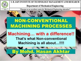
- 1. NON-CONVENTIONAL MACHINING PROCESSES By Mohd. Hasan Akhtar Machining… with a difference!! That’s what Non-conventional Machining is all about…!!!!
- 2. Types of Non-conventional Machining Processes 1. Electrical Discharge Machining 2. Electrochemical Machining 3. Laser Beam Machining 4. Electron Beam Machining 5. Plasma Arc Cutting 6. Ultrasonic Machining 7. Water Jet Machining 8. Abrasive Jet Machining SBJITMR, NAGPUR 2M. Hasan Akhtar (8180818280)
- 3. The Need for Non-conventional Machining Processes Traditional machining processes • Material removal by mechanical means, such as chip forming, abrasion, or micro-chipping Advanced machining processes • Utilize chemical, electrical, and high-energy beams The following cannot be done by traditional processes: a. Workpiece strength and hardness very high,>400HB b. Workpiece material too brittle, glass, ceramics, heat-treated alloys c. Workpiece too slender and flexible, hard to clamp d. Part shape complex, long and small hole e. Special surface and dimensional tolerance requirements SBJITMR, NAGPUR 3M. Hasan Akhtar (8180818280)
- 4. Classification of NTM processes The Non-traditional Machining Methods are classified according to the major energy sources employed in machining. 1. Thermal Energy Methods 2. Electro - Chemical Energy Method 3. Chemical Energy Methods 4. Mechanical Energy Methods SBJITMR, NAGPUR 4M. Hasan Akhtar (8180818280)
- 5. Classification (Contd.) 1. Thermal Energy Methods: In these methods, the thermal energy is employed to melt and vaporize tiny particles of work- material by concentrating the heat energy on a small area of the workpiece. The required shape is obtained by the continued repetition of this process. These methods include: a) Electrical discharge machining (EDM) b) Laser beam Machining (LBM) c) Plasma Arc Machining (PAM) d) Electron Beam Machining(EBM) e) Ion Beam Machining (IBM) SBJITMR, NAGPUR 5M. Hasan Akhtar (8180818280)
- 6. Classification (Contd.) 2. Electro - Chemical Energy Method: These methods involve electrolytic (anodic) dissolution of the workpiece material in contact with a chemical solution. These methods include: a) Electro-Chemical Machining (ECM) b) Electro-Chemical grinding (ECG) c) Electro-Chemical Honing (ECH) d) Electro-Chemical Deburring (ECD) SBJITMR, NAGPUR 6M. Hasan Akhtar (8180818280)
- 7. Classification (Contd.) 3. Chemical Energy Methods: These methods involve controlled etching of the workpiece material in contact with a chemical solution. 1. Chemical Machining Method (CHM). SBJITMR, NAGPUR 7M. Hasan Akhtar (8180818280)
- 8. Classification (Contd.) 4. Mechanical Energy Methods: In these methods, the material is principally removed by mechanical erosion of the workpiece material. These methods include: a) Ultra Sonic Machining (USM) b) Abrasive Jet Machining (AJM) c) Water Jet Machining (WJM) SBJITMR, NAGPUR 8M. Hasan Akhtar (8180818280)
- 9. GATE-2014 The process utilizing mainly thermal energy for removing material is (a) Ultrasonic Machining (b) Electrochemical Machining (c) Abrasive Jet Machining (d) Laser Beam Machining M. Hasan Akhtar (8180818280) 9SBJITMR, NAGPUR
- 10. Capabilities of NTM 1. EDM has the lowest specific power requirement and can achieve sufficient accuracy. 2. ECM has the highest metal removal rate, MRR. 3. USM and AJM have low MRR and combined with high tool wear, are used for non-metal cutting. 4. LBM and EBM have high penetration rates with low MRR and, therefore, are commonly used for micro drilling, sheet cutting, and welding. 5. CHM is used for manufacturing PCB and other shallow components. 6. PAM can be used for clean, rapid cuts and profiles in almost all plates upto 20 cm thick with 5o to 10o taper. M. Hasan Akhtar (8180818280) 10SBJITMR, NAGPUR
- 11. Shapes Cutting Capability The various NTMM have some special shape cutting capability as given below: 1. Micro-machining and Drilling : LBM, EBM and micro-EBM 2. Cavity sinking and standard Hole Drilling: EDM and USM 3. Fine hole drilling and Contour Machining: ECM 4. Clean, rapid Cuts and Profiles: PAM 5. Shallow Pocketing: AJM M. Hasan Akhtar (8180818280) 11SBJITMR, NAGPUR
- 12. GATE-2014 The following four unconventional machining processes are available in a shop floor. The most appropriate one to drill a hole of square cross section of 6 mm × 6 mm and 25 mm deep is (a) Abrasive Jet Machining (b) Plasma Arc Machining (c) Laser Beam Machining (d) Electro Discharge Machining M. Hasan Akhtar (8180818280) 12SBJITMR, NAGPUR
- 13. Limitations of NTMM 1. Expensive set up, low MRR and skilled labour required. 2. The limitation of electrical machining methods is that the work material must be an electrical conductor. 3. Consumption of electrical energy is very large. 4. The NTMM which have not been proved commercially economical are: USM, AJM, CHM, EBM and PAM. M. Hasan Akhtar (8180818280) 13SBJITMR, NAGPUR
- 14. Process Selection The common parameters to be taken into consideration for selecting a particular process are the following: 1. Physical properties of the work material. 2. Type of operation required - cutting, hole making, etc. 3. Shape and size required to be produced. 4. Process capabilities; such as, expected tolerance, surface finish, rate of metal power requirement, etc. 5. Processes economy. SBJITMR, NAGPUR 14M. Hasan Akhtar (8180818280)
- 15. IES - 2012 Which of the following processes has very high material removal rate efficiency? (a) Electron beam machining (b) Electrochemical machining (c) Electro discharge machining (d) Plasma arc machining M. Hasan Akhtar (8180818280) 15SBJITMR, NAGPUR
- 16. GATE - 2006 Arrange the processes in the increasing order of their maximum material removal rate. Electrochemical Machining (ECM) Ultrasonic Machining (USM) Electron Beam Machining (EBM) Laser Beam Machining (LBM) and Electric Discharge Machining (EDM) (a) USM, LBM, EBM, EDM, ECM (b) EBM, LBM, USM, ECM, EDM (c) LBM, EBM, USM, ECM, EDM (d) LBM, EBM, USM, EDM, ECM M. Hasan Akhtar (8180818280) 16SBJITMR, NAGPUR
- 17. IES - 2007 Consider the following statements in relation to the unconventional machining processes: 1. Different forms of energy directly applied to the piece to have shape transformation or material removal from work surface. 2. Relative motion between the work and the tool is essential. 3. Cutting tool is not in physical contact with work piece. (a) 1 and 2 only (b) 1, 2 and 3 only (c) 2 and 3 only(d) 1 and 3 only M. Hasan Akhtar (8180818280) 17SBJITMR, NAGPUR
- 18. IES - 2009 Which one of the following statements is correct in respect of unconventional machining processes? (a) The cutting tool is in direct contact with the job (b) The tool material needs to be harder than the job material (c) The tool is never in contact with the job (d) There has to be a relative motion between the tool and the job M. Hasan Akhtar (8180818280) 18SBJITMR, NAGPUR
- 19. IAS - 2002 Match List I (Processes) with List II (Tolerances obtained) and select the correct answer using the codes given below the Lists: List I List II (Processes) (Tolerances obtained) A. Plasma Arc machining 1. 7·5 microns B. Laser Beam machining 2. 25 microns C. Abrasive Jet machining 3. 50 microns D. Ultrasonic machining 4. 125 microns Codes:A B C D A B C D (a) 4 1 3 2 (b) 3 2 4 1 (c) 4 2 3 1 (d) 3 1 4 2 M. Hasan Akhtar (8180818280) 19SBJITMR, NAGPUR
- 20. EDM M. Hasan Akhtar (8180818280) 20SBJITMR, NAGPUR
- 21. Electrical Discharge Machining SBJITMR, NAGPUR 21 It is also known as Spark over-initiated discharge machining, Spark erosion machining or simply Spark machining. It is probably the most versatile of all the electrical machining methods. Mechanics of material removal - melting and evaporation aided by cavitations. This process may be used for machining any material, irrespective of its hardness, which is an electrical conductor. M. Hasan Akhtar (8180818280)
- 22. Electrical Discharge Machining The rate of metal removal and the resulting surface finish can be controlled by proper variation in the energy and the duration of spark discharge. A liquid dielectric, like paraffin or some light oil, like transformer oil or kerosene oil, is always used in the process. SBJITMR, NAGPUR 22M. Hasan Akhtar (8180818280)
- 23. Electrical Discharge Machining (EDM) SBJITMR, NAGPUR 23 Figure 1: Schematic Diagram of EDM M. Hasan Akhtar (8180818280)
- 24. EDM (Contd.) SBJITMR, NAGPUR 24 Figure 2: Schematic Diagram of EDM M. Hasan Akhtar (8180818280)
- 25. EDM Set-up The main elements of this setup include 1. Power supply source 2. Dielectric medium 3. Workpiece and tool 4. Servo control 5. Speed reduction gear box 6. A rack and pinion or some other suitable mechanism for tool feed 7. An electric circuit to generate discharge, etc. SBJITMR, NAGPUR 25M. Hasan Akhtar (8180818280)
- 26. EDM Set-up (Contd.) Both, the tool and the work piece are connected to the D. C. Electric supply source. The workpiece is connected to the positive terminal The tool to the negative terminal of the power source. Consequently, the work piece becomes Anode and the tool Cathode. SBJITMR, NAGPUR 26M. Hasan Akhtar (8180818280)
- 27. EDM Working The workpiece and the electrode (tool) are separated by a gap, called Spark gap, ranges from 0.005 mm to 0.05 mm. This gap is filled up by the dielectric, which breaks down when a proper voltage is applied between these two. A circuit voltage of 50 V to 450 V is applied, electrons start flowing from the cathode, due to the electrostatic field, and the gap is ionized. The consequent drop in resistance and discharge of electric energy results in an electrical breakdown. The electric spark so caused directly impinges on the surface of the workpiece. It takes only a few micro seconds to complete the cycle and the spark discharges hit the workpiece with considerable force and velocity, resulting in the development of a very high temperature (around 10,000°C) on the spot hit by the discharges. SBJITMR, NAGPUR 27M. Hasan Akhtar (8180818280)
- 28. EDM Working This forces the metal to melt, and a portion of it may be vaporized even. These vaporized or melted particles of the metal are thrown into the gap by the electrostatic and electromagnetic forces, from where they are driven away by the flowing liquid dielectric. It should be remembered that erosion takes place on both, the tool as well as the workpiece, but the former is eroded much less as compared to the latter. It is because the tool tip is subjected to compressive forces due to the electric and magnetic fields, resulting in a slower erosion of the metal from its surface. The rate of metal removal depends upon the discharge current, duration of pulse and the rate of pulse repetition. SBJITMR, NAGPUR 28M. Hasan Akhtar (8180818280)
- 29. Tool Electrode Prime requirements EDM tool Material 1. It should be electrically conductive. 2. It should have good machinability, thus allowing easy manufacture of complex shapes. 3. It should have low erosion rate or good work to tool wear ratio. 4. It should have low electrical resistance. 5. It should have high melting point. 6. It should have high electron emission. SBJITMR, NAGPUR 29M. Hasan Akhtar (8180818280)
- 30. EDM Tool The usual choices for tool (electrode) materials are • Copper, • brass, • alloys of zinc and tin, • hardened plain carbon steel, • copper tungsten, • silver tungsten, • tungsten carbide, • copper graphite, and graphite. M. Hasan Akhtar (8180818280) 30SBJITMR, NAGPUR
- 31. Wear Ratio One major drawback of EDM is the wear that occurs on the electrode at each spark. Tool wear is given in terms of wear ratio which is defined as, Wear ratio for brass electrode is 1: 1. For most other metallic electrodes, it is about 3: 1 or 4: 1. With graphite (with the highest melting point, 3500°C), the wear ratio may range from 5: 1 up to 50: 1. Volume of metal removed work Wear ratio = Volume of metal removed tool M. Hasan Akhtar (8180818280) 31SBJITMR, NAGPUR
- 32. Dielectric Fluid 1. Fluid is used to act as a dielectric, and to help carry away debris. 2. If the fluid is pumped through and out the end of the electrode, particles will push out, and mainly collect at the edges. They will lower the dielectric resistance, resulting in more arcs. As a result the holes will be conical. 3. If fluid is vacuum pumped into the electrode tip, straight holes will result. 4. Quite often kerosene-based oil. 5. The dielectric fluid is circulated through the tool at a pressure of 0.35 N/m2 or less. To free it from eroded metal particles, it is circulated through a filter. SBJITMR, NAGPUR 32M. Hasan Akhtar (8180818280)
- 33. Advantages 1. Hardness, toughness or brittleness of the material poses no problems. Due to this EDM can be used for machining materials that are too hard or brittle to be machined by conventional methods. 2. The method does not leave any chips or burrs on the work piece. 3. Cutting forces are virtually zero, so very delicate and fine work can be done. 4. The process dimension repeatability and surface finish obtained in finishing are extremely good. 5. The characteristic surface obtained, which is made up of craters, helps in better oil retention. This improves die life. M. Hasan Akhtar (8180818280) 33SBJITMR, NAGPUR
- 34. Disadvantages 1. Only electrically conductive materials can be machined by EDM. Thus non - metallic, such as plastics, ceramics or glass, cannot be machined by EDM. 2. Electrode wear and over-cut are serious problems. 3. A re-hardened, highly stressed zone is produced on the work surface by the heat generated during machining. This brittle layer can cause serious problems when the part is put into service. 4. Perfectly square corners cannot be made by EDM. 5. High specific energy consumption (about 50 times that in conventional machining) 6. MRR is quite low M. Hasan Akhtar (8180818280) 34SBJITMR, NAGPUR
- 35. Applications The EDM process offers the following main Applications: 1. This process is very useful in tool manufacturing due to the ease with which hard materials and alloys can be machined. 2. Re-sharpening of cutting tools. 3. Manufacturing of die SBJITMR, NAGPUR 35M. Hasan Akhtar (8180818280)
- 36. IES - 2012 Statement (I): In Electro Discharge Machining (EDM) process, tool is made cathode and work piece anode Statement (II): In this process if both electrodes are made of same material, greatest erosion takes place upon anode (a) Both Statement (I) and Statement (II) are individually true and Statement (II) is the correct explanation of Statement (I) (b) Both Statement (I) and Statement (II) are individually true but Statement (II) is not the correct explanation of Statement (I) (c) Statement (I) is true but Statement (II) is false (d) Statement (I) is false but Statement (II) is true M. Hasan Akhtar (8180818280) 36SBJITMR, NAGPUR
- 37. GATE - 2004 The mechanism of material removal in EDM process is (a) Melting and Evaporation (b) Melting and Corrosion (c) Erosion and Cavitation (d) Cavitation and Evaporation M. Hasan Akhtar (8180818280) 37SBJITMR, NAGPUR
- 38. GATE - 2003 As tool and work are not in contact in EDM process (a) No relative motion occurs between them (b) No wear of tool occurs (c) No power is consumed during metal cutting (d) No force between tool and work occurs M. Hasan Akhtar (8180818280) 38SBJITMR, NAGPUR
- 39. GATE - 1999 In Electro-Discharge Machining (EDM), the tool is made of (a) Copper (b) High Speed Steel (c) Cast Iron (d) Plain Carbon Steel M. Hasan Akhtar (8180818280) 39SBJITMR, NAGPUR
- 40. GATE-2010 (PI) Keeping all other parameters unchanged, the tool wear in electrical discharge machining (EDM) would be less if the tool material has (a) high thermal conductivity and high specific heat (b) high thermal conductivity and low specific heat (c) low thermal conductivity and low specific heat (d) low thermal conductivity and high specific heat M. Hasan Akhtar (8180818280) 40SBJITMR, NAGPUR
- 41. GATE - 2007 In electro discharge machining (EDM), if the thermal conductivity of tool is high and the specific heat of work piece is low, then the tool wear rate and material removal rate are expected to be respectively (a) High and high (b) Low and low (c) High and low (d) Low and high M. Hasan Akhtar (8180818280) 41SBJITMR, NAGPUR
- 42. IES - 2005 Which of the following is/are used as low wearing tool material(s) in electric discharge machining? (a) Copper and brass (b) Aluminium and graphite (c) Silver tungsten and copper tungsten (d) Cast iron M. Hasan Akhtar (8180818280) 42SBJITMR, NAGPUR
- 43. GATE- 2000 Deep hole drilling of small diameter, say 0.2 mm is done with EDM by selecting the tool material as (a) Copper wire (b) Tungsten wire (c) Brass wire (d) Tungsten carbide M. Hasan Akhtar (8180818280) 43SBJITMR, NAGPUR
- 44. ECM M. Hasan Akhtar (8180818280) 44SBJITMR, NAGPUR
- 45. Electro-chemical Machining (ECM) ECM is an extension of electroplating with some modifications, but in a reverse direction. Thus ECM can be describe as a controlled anodic dissolution at atomic level of the work piece that is electrically conductive by a shaped tool due to flow of high current at relatively low potential difference through an electrolyte which is quite often water based neutral salt solution. SBJITMR, NAGPUR 45M. Hasan Akhtar (8180818280)
- 46. Electro-chemical Machining (ECM) SBJITMR, NAGPUR 46M. Hasan Akhtar (8180818280) Figure: Schematic basic Principle of Electro chemical Machining (ECM)
- 47. Electrochemical Machining SBJITMR, NAGPUR 47M. Hasan Akhtar (8180818280)
- 48. ECM Working 1. The principle of ECM process is based on Faraday's Laws of Electrolysis. 2. A reverse shaped tool or electrode is used in the process, which forms cathode. The workpiece forms anode. 3. The tool and workpiece are held on each other with a very small gap 0.2mm to 2mm between them. 4. A mild D.C. Supply Voltage 2 to 35 V and Current 50A to 40,000 A is applied between the two and an electrolyte continuously pumped into the gap. SBJITMR, NAGPUR 48M. Hasan Akhtar (8180818280)
- 49. ECM Working 5. Due to the applied voltage the current flows through the electrolyte with positively charged ion being attracted towards the tool (Cathode) and the negatively charged ions towards the workpiece (anode). 6. The electrolyte needs to be pumped through this gap at high pressures ranging from 0.5 to 20 bar. 7. The electrochemical reaction, taking place due to this flow of ions results in the removal of metal from the workpiece in the form of sludge. 8. This sludge is taken away from the gap by the flowing electrolyte along with it. SBJITMR, NAGPUR 49M. Hasan Akhtar (8180818280)
- 50. Faraday’s Law First Statement: Amount of Electrochemical dissolution or deposition proportional to amount of charge that being passed through electro chemical Cell. Where ‘m’ is amount of electrochemical dissolution i.e. mass and Q is charge Second Statement: Amount of material dissolved or deposited depends on Electro Chemical Equivalence (ECE= Ration of Atomic Weight and valency.) SBJITMR, NAGPUR 50M. Hasan Akhtar (8180818280) m Q A m ECE
- 51. Faraday’s Law SBJITMR, NAGPUR 51M. Hasan Akhtar (8180818280) Q A It A m ' 96500 It A m F F Faraday s Const C 3 3 ( / sec) / m ItA IA I ECE MRR cm t F t F F in gm cm
- 52. Faraday’s Law SBJITMR, NAGPUR 52M. Hasan Akhtar (8180818280) 3 . ( / sec) 1 i i i i I MRR ECE cm F ECE A wt fraction of alloy For Alloy
- 53. Other Important Relations SBJITMR, NAGPUR 53M. Hasan Akhtar (8180818280) 1 1 2 1 Re / ( ) s s s Electrode Feed Rate s S ECE SpecificMaterial moval Rate s F I Current Density S A A c s area perpendicular to current flow m V I R l R electrical resistivity A V S l Gap betweentool and electrode l
- 54. GATE-2014 The principle of material removal in Electro- chemical machining is (a) Fick’s law (b) Faraday’s laws (c) Kirchhoff’s laws (d) Ohm’s law M. Hasan Akhtar (8180818280) 54SBJITMR, NAGPUR
- 55. Tool Electrode The properties of tool materials should be: 1. High electrical and thermal conductivity 2. Easy machine-ability 3. Good stiffness 4. High corrosion resistance Tool materials: Copper, brass, bronze, Al, Stainless Steel, nickel, etc. Material wear / Tool wear: Infinite SBJITMR, NAGPUR 55M. Hasan Akhtar (8180818280)
- 56. Electrolyte in ECM The electrolyte is so chosen that the anode (workpiece) is dissolved but no deposition takes place on the cathode (tool). • Material NaCl and NaNO3 • Temperature 20oC – 50oC • Flow rate 20 lpm per 100 A current • Pressure 0.5 to 20 bar • Dilution 100 g/l to 500 g/l SBJITMR, NAGPUR 56M. Hasan Akhtar (8180818280)
- 57. Electrolyte in ECM The electrolyte is so chosen that the anode (workpiece) is dissolved but no deposition takes place on the cathode (tool). Properties electrolyte should be 1. High electrical conductivity 2. Low viscosity 3. Chemical stability 4. Resistance to formation of film on workpiece surface 5. Non-corrosive and non-toxic 6. Inexpensive and readily available SBJITMR, NAGPUR 57M. Hasan Akhtar (8180818280)
- 58. Advantages The ECM process offers the following main advantages: 1. Hardness, toughness or brittleness of the material poses no problems. 2. The method does not leave any chips or burrs on the work piece. SBJITMR, NAGPUR 58M. Hasan Akhtar (8180818280)
- 59. Disadvantages The ECM process offers the following main disadvantages: 1. Use of corrosive media as electrolytes makes it difficult to handle. 2. Sharp interior edges and corners (< 0.2 mm radius) are difficult to produce. 3. Very expensive machine. 4. Forces are large with this method because of fluid pumping forces. 5. Very high specific energy consumption (about 150 times that required for conventional processes), 6. Not applicable with electrically non-conducting materials and jobs with very small dimensions SBJITMR, NAGPUR 59M. Hasan Akhtar (8180818280)
- 60. ISRO-2009 The machining process in which the work picce is dissolved into an electrolyte solution is called (a) Electro-chemical machining (b) Ultrasonic machining (c) Electro-discharge machining (d) Laser machining M. Hasan Akhtar (8180818280) 60SBJITMR, NAGPUR
- 61. PSU ECM cannot be undertaken for (a) steel (b) Nickel based super alloy (c) Al2O3 (d) Titanium alloy M. Hasan Akhtar (8180818280) 61SBJITMR, NAGPUR
- 62. Applications The ECM process offers the following main Applications: 1. Machining of hard to machine and heat resistance materials. 2. Machining of blind holes and pockets, such as in forging dies. 3. Machining of complicated profiles, such as of jet engine blades, turbine blades turbine wheels, etc. 4. Drilling small deep holes, such as in nozzles. 5. Machining of cavities and holes of irregular shapes. 6. Deburring of parts. SBJITMR, NAGPUR 62M. Hasan Akhtar (8180818280)
- 63. Electro-chemical Machining QUIZ 1. For ECM of steel which is used as the electrolyte a) kerosene b) NaCl c) Deionised water d) HNO3 2. MRR in ECM depends on a) Hardness of work material b) atomic weight of work material c) thermal conductivity of work material d) ductility of work material SBJITMR, NAGPUR 63M. Hasan Akhtar (8180818280)
- 64. Electro-chemical Machining QUIZ 3. ECM cannot be undertaken for (a) steel (b) Nickel based super alloy (c) Al2O3 (d) Titanium alloy 4. Commercial ECM is carried out at a combination of (a) low voltage high current (b) low current low voltage (c) high current high voltage (d) low current low voltage SBJITMR, NAGPUR 64M. Hasan Akhtar (8180818280)
- 65. SBJITMR, NAGPUR 65 Electron Beam Machining M. Hasan Akhtar (8180818280)
- 66. Electron Beam Machining (Principle) Electron Beam Machining (EBM) is a thermal process. Here a steam of high speed electrons impinges on the work surface so that the kinetic energy of electrons is transferred to work producing intense heating. Depending upon the intensity of heating the workpiece can melt and vaporize. The process of heating by electron beam is used for annealing, welding or metal removal. SBJITMR, NAGPUR 66M. Hasan Akhtar (8180818280)
- 67. Electron Beam Machining It is a process of machining materials with the use of a high velocity beam of electrons. The workpiece is held in a vacuum chamber and the electron beam focused on to it magnetically. As the electrons strike the workpiece, their kinetic energy is converted into heat. This concentrated heat raises the temperature of workpiece materials and vaporizes a small amount of it, resulting in removal of metal from the workpiece. The reason for using a vacuum chamber is that, if otherwise, the beam electrons will collide with gas molecules and will scatter. SBJITMR, NAGPUR 67M. Hasan Akhtar (8180818280)
- 68. SBJITMR, NAGPUR 68M. Hasan Akhtar (8180818280)
- 69. EBM Set-up The main elements of Electron Beam Machining setup are shown in Figure. 1. Vacuum Chamber, which carries vacuum of the order of l0-5 mm of mercury. 2. Door, through which the workpiece is placed over the table in side the chamber carries 3. The Electron gun, which is mainly responsible for emission of electrons, consists of three main parts: i. Tungsten filament, ii. Grid cup and iii. Anode. 4. The filament is connected to the - ve terminal of the D.C. Power supply, to act as cathode, and the anode to the + ve terminal, as shown. SBJITMR, NAGPUR 69M. Hasan Akhtar (8180818280)
- 70. Electron Beam Machining Aperture: It captures the stray electrons, so that focused electron beam obtained. Electromagnetic Lens: It works as focusing lens and focuses the electron beam to a desired spot. Deflector coil: Electron beam can also be maneuvered using the electromagnetic deflection coils for drilling holes of any shape, though by small amount, to improve shape of the machined holes. SBJITMR, NAGPUR 70M. Hasan Akhtar (8180818280)
- 71. SBJITMR, NAGPUR 71M. Hasan Akhtar (8180818280)
- 72. SBJITMR, NAGPUR 72M. Hasan Akhtar (8180818280)
- 73. SBJITMR, NAGPUR 73M. Hasan Akhtar (8180818280)
- 74. Electron Beam Machining 1. The filament wire is heated to a temperature of about 2500°C in the vacuum. With the result, a cloud of electrons is emitted by the filament, which is directed by the grid cup to travel downwards. 2. As the electrons are attracted by the anode, they pass through its aperture in the form of a controlled beam without colliding with it. 3. A potential difference of 30 to 150 kV is maintained between the filament and the anode. 4. As such, the electrons passing through the anode are accelerated to achieve as high a velocity as around two-third of light. 5. The maximum velocity attained by the electrons, while passing out of anode, is maintained by them till such time as they strike the workpiece. 6. It becomes possible because the electrons travel through the vacuum. SBJITMR, NAGPUR 74M. Hasan Akhtar (8180818280)
- 75. Electron Beam Machining 7. This high velocity electron stream, after leaving the anode, passes through the tungsten diaphragm and then through the electromagnetic focusing coils (or focusing lens). 8. By then, the stream is quite aligned and the focusing lens manages to focus it precisely on to the desired spot on the workpiece. 9. The electromagnetic Deflector Coil then deflects this aligned stream (beam) on to the work, through which the path of cut can be controlled. 10. Further, the table on which the workpiece is loaded, can also be traversed to feed the workpiece as needed. 11. This high velocity beam of electrons impinges on the workpiece, where its kinetic energy is released and gets converted into heat energy. The high intensity heat, so produced, melts and vaporizes the work material at the spot of beam impingement. SBJITMR, NAGPUR 75M. Hasan Akhtar (8180818280)
- 76. Electron Beam Machining Mechanism of MRR Thermo ionic electrons (As the potential difference is applied between cathode and anode, electrical filament get heated near about at 2500 C and emits electron which are repelled by cathode and attract by anode) Acceleration of electron due to anode potential (Accelerated to almost half of the velocity of light) High velocity beam of electron Shaping and focusing of electron beam (this electron beam is shaped and focused by a series of magnetic and electro magnetic lenses) Impingement of high velocity electron beam on the work Spot size 10 to 100 microns, high energy density (10^4 watt/mm2) Heating, melting and vaporization leading to drilling SBJITMR, NAGPUR 76M. Hasan Akhtar (8180818280)
- 77. Electron Beam Machining SBJITMR, NAGPUR 78M. Hasan Akhtar (8180818280) EBM Process Parameters • The accelerating voltage (30 to 150kV) • The beam current (250 A to 1A) • Pulse duration (50 s to 50ms) • Energy per pulse (100J/Pulse) • Power per pulse • Lens current • Spot size (10 m to 100 m) • Power density
- 78. GATE-2016 The non-traditional machining process that essentially requires vacuum is (a) electron beam machining (b) electro chemical machining (c) electro chemical discharge machining (d) electro discharge machining M. Hasan Akhtar (8180818280) 79SBJITMR, NAGPUR
- 79. Advantages The EBM process offers the following main advantages: 1. Workpiece is not subjected to any physical or metallurgical damage because about 25-50 μm away from machining spot remains at room temperature and so no effects of high temperature on work. 2. Problem of tool wear is non-existent. So, close dimensional tolerances can be achieved. 3. Heat can be concentrated on a particular spot. 4. An excellent technique for micro machining and Any material can be machined. 5. Highly reactive metals like Al and Mg can be machined very easily. SBJITMR, NAGPUR 80M. Hasan Akhtar (8180818280)
- 80. Disadvantages The EBM process offers the following main disadvantages: 1. Material removal rate is very low compared to other unconventional machining processes. 2. Maintaining perfect vacuum is very difficult moreover Workpiece size is limited due to requirement of vacuum in the chamber. 3. The machining process can’t be seen by operator. 4. Not suitable for producing perfectly cylindrical deep holes. 5. High power consumption. 6. Difficult to produce slots and holes of uniform shapes and dimensions. SBJITMR, NAGPUR 81M. Hasan Akhtar (8180818280)
- 81. Applications The EBM process offers the following main Applications: 1. Very effective for machining of materials of low heat conductivity and high melting point. 2. Micro-machining operations on workpieces of thin sections. 3. Micro-drilling operations (up to 0.002 mm) for thin orifices, dies for wire drawing, parts of electron microscopes, fiber spinners, injector nozzles for diesel engines etc. 4. Used only for circular holes. SBJITMR, NAGPUR 82M. Hasan Akhtar (8180818280)
- 82. SBJITMR, NAGPUR 83 Laser Beam Machining M. Hasan Akhtar (8180818280)
- 83. Laser Beam Machining (Principle) Laser beam machining (LBM) uses the light energy from a laser device for the material removal by vaporization. Laser is the term used for the phenomenon of 'amplification of light’ by stimulated emission of radiation’. A laser is an optical transducer that converts electrical energy into a highly coherent light beam. The energy of the coherent light beam is concentrated not only optically but also with time. SBJITMR, NAGPUR 84M. Hasan Akhtar (8180818280)
- 84. Laser Beam Machining The setup consists of a stimulating light source (like flash lamp) and a laser rod. The light radiated from the flash lamp is focused on to the laser rod (Laser tube), from where it is reflected and accelerated in the path. This light is emitted in the form of a slightly divergent beam. A lens is incorporated suitably in the path of this beam of light which converges and focuses the light beam on to the workpiece to be machined. This concentration of the laser beam on the workpiece melts the work material and vaporizes it. It is very costly method and can be employed only when it is not feasible to machine a workpiece through other methods. SBJITMR, NAGPUR 85M. Hasan Akhtar (8180818280)
- 85. SBJITMR, NAGPUR 86M. Hasan Akhtar (8180818280)
- 86. M. Hasan Akhtar (8180818280) SBJITMR, NAGPUR 87
- 87. LBM Set-up It mainly consists of Laser tube or rod, the types of lasers used in LBM are carbon dioxide gas lasers and solid-state lasers. Pair of mirrors - one at each end of the tube, Flash tube or lamp (energy source), Amplifying source (laser), Power supply source, Cooling system and Lens (focusing source). The main setup is fitted inside an Enclosure, which carries a highly reflective surface inside. SBJITMR, NAGPUR 88M. Hasan Akhtar (8180818280)
- 88. LBM Operation In operation, the optical energy (light) is thrown by the flash lamp on to the laser tube (Ruby rod). This excites the atoms of the inside media, which absorb the radiation of incoming light energy. This results in the to and fro travel of light between the two reflecting mirrors. But, the partial reflecting mirror does not reflect the total light back and a part of it goes out in the form of a coherent stream of monochromatic light. SBJITMR, NAGPUR 89M. Hasan Akhtar (8180818280)
- 89. LBM Operation This highly amplified stream of light is focused through a lens, which converges it to a chosen point on the workpiece. This high intensity converged laser beam, when falls on the workpiece, melts the workpiece material, vaporizes it almost instantaneously and penetrates into it. Thus, it can be called a type of thermal cutting process. SBJITMR, NAGPUR 90M. Hasan Akhtar (8180818280)
- 90. LBM Operation SBJITMR, NAGPUR 91M. Hasan Akhtar (8180818280)
- 91. Advantages The LBM process offers the following main advantages: 1. Any material can be easily machined irrespective of its structure and physical and mechanical properties. 2. Unlike conventional machining, there is no direct contact between the tool and the workpiece and no involvement of large scale cutting forces. 3. Can be effectively used for welding of dissimilar metals as well 4. Small heat effected zone around the machined surface. 5. Very small holes and cuts can be made with fairly high degree of accuracy. SBJITMR, NAGPUR 92M. Hasan Akhtar (8180818280)
- 92. Disadvantages The LBM process offers the following main disadvantages: 1. High capital investment needed. 2. Operating cost is also quite high. 3. Highly skilled operators are needed. 4. Production rate is low. 5. Its application is limited to only the thin sections and where a very small amount of metal removal is involved. 6. Cannot be effectively used to machine highly heat conductive and reflective materials. SBJITMR, NAGPUR 93M. Hasan Akhtar (8180818280)
- 93. Applications The LBM process offers the following main Applications: 1. Trimming of carbon resistors. 2. Drilling small holes in hard materials like tungsten and ceramics. 3. Cutting complex profiles on thin and hard materials. 4. Cutting or engraving patterns on thin films. 5. Dynamic balancing of precision rotating components, such as of watches. 6. Trimming of sheet metal and plastic parts. SBJITMR, NAGPUR 94M. Hasan Akhtar (8180818280)
- 94. Ultrasonic Machining M. Hasan Akhtar (8180818280) 95SBJITMR, NAGPUR
- 95. Ultrasonic Machining M. Hasan Akhtar (8180818280) 96SBJITMR, NAGPUR
- 96. Subsystems of USM B E C D A M. Hasan Akhtar (8180818280) 97SBJITMR, NAGPUR
- 97. Ultrasonic Machining SBJITMR, NAGPUR 98M. Hasan Akhtar (8180818280)
- 98. Transducer The ultrasonic vibrations are produced by the transducer. The transducer is driven by suitable signal generator followed by power amplifier. The transducer for USM works on the following principle Piezoelectric effect Magnetostrictive effect Electrostrictive effect Magnetostrictive transducers are most popular and robust amongst all. M. Hasan Akhtar (8180818280) 99SBJITMR, NAGPUR
- 99. GATE -2010 (PI) Ultrasonic machines, used in material removal processes, require ultrasonic transducers. The transducers works on different working principles. One of the working principles of such ultrasonic transducers is based on (a) eddy current effect (b) Seebeck effect (c) piezo-resistive effect (d) piezo-electric effect M. Hasan Akhtar (8180818280) 100SBJITMR, NAGPUR
- 100. Tool Electrode in USM The tool is made of relatively soft metal. It is applied to the workpiece surface and the Slurry applied either manually or through a pump. The tool can be attached to the arbor either by brazing, hard soldering or screwing. Sometimes hollow tools are used which facilitate feeding of the slurry through them. The main advantage of this process is that the workpiece after being machined is normally free from residual mechanical stresses and a high degree of surface finish can be obtained. SBJITMR, NAGPUR 101M. Hasan Akhtar (8180818280)
- 101. Ultrasonic Machining A high frequency electric current is sent by the ultrasonic oscillator to the ultrasonic transducer. The function of the transducer is to convert this electrical energy into mechanical vibrations. The vibrations so generated are of the order of 20 kHz to 30 kHz, although the available amplitude usually varies from 15 – 50 μm . The transducer is made of a magneto strictive material, which is excited by the following high frequency electric current and this results in the generation of mechanical vibrations. These vibrations are then transmitted to the cutting fool via the intermediate connecting parts, such as transducer cone or horn, connecting body and tool holder. SBJITMR, NAGPUR 103M. Hasan Akhtar (8180818280)
- 102. Ultrasonic Machining Slurry of small abrasive particles is forced against the work by means of a vibrating tool, removing the workpiece material in the form of extremely small chips. The grains used are of silicon carbide, aluminum oxide, boron carbide or diamond dust. This processes is suitable only for hard and brittle materials like carbides, glass, ceramics, silicon, precious stones, germanium, titanium, tungsten, tool steels, die steels, ferrite quartz, etc. The vibrating frequency used for the tool is of the order of over 20,000 oscillations second. Such a high frequency, which is more than the upper limit of audible frequency for human ear' makes the process inaudible (silent). SBJITMR, NAGPUR 104M. Hasan Akhtar (8180818280)
- 103. Ultrasonic Machining This makes the tool vibrate in a longitudinal direction, as, shown. The intermediate parts together form what is known as the focusing unit and the cutting tool is fastened at its end. The shape of the cutting tool is the same as that of the cavity to be produced by it. The slurry, formed by the suspension of abrasive grains in a carrier fluid, is fed into the machining area by means of a circulating pump. However, in order to keep its temperature low a suitable cooling system may be incorporated. SBJITMR, NAGPUR 105M. Hasan Akhtar (8180818280)
- 104. Process Parameters M. Hasan Akhtar (8180818280) 106SBJITMR, NAGPUR
- 105. Effect of machining parameters on MRR •Feed force (F) •Amplitude of vibration (ao) •average grit diameter, dg •Frequency of vibration (f) •Volume concentration of abrasive in water slurry – C M. Hasan Akhtar (8180818280) 107SBJITMR, NAGPUR
- 106. GATE-2016 In an ultrasonic machining (USM) process, the material removal rate (MRR) is plotted as a function of the feed force of the USM tool. With increasing feed force, the MRR exhibits the following behaviour: (a) increasing linearly (b) decreases linearly (c) does not change (d) first increases and then decreases M. Hasan Akhtar (8180818280) 108SBJITMR, NAGPUR
- 107. Advantages The USM process offers the following main Advantages: 1. Extremely hard and brittle materials can be easily machined. 2. Highly accurate profiles and good surface finish can be easily obtained. 3. The machined Workpiece are free of stresses. 4. Metal removal cost is low. 5. Due to practically no heat generation in the process, the physical properties of the 6. Work material remain unchanged. 7. The operation is noiseless. 8. Operation of the equipment is quite safe. SBJITMR, NAGPUR 109M. Hasan Akhtar (8180818280)
- 108. Disadvantages The USM process offers the following main Advantages: 1. The metal removal rate is low. 2. The initial equipment cost is higher than the conventional machine tools. 3. This process does not suit to heavy metal removal. 4. The cost of tooling is also high. 5. Difficulties are encountered in machining softer materials. 6. Power consumption is quite high. 7. High wear rate of tool may lead to dimensionally inaccurate machined parts. So, for accurate machining, the tool may have to be replaced quite often, especially while machining blind cavities. 8. In order to maintain an efficient cutting action, the slurry may have to be replaced periodically 9. The size of the cavity that can be machined is limited. SBJITMR, NAGPUR 110M. Hasan Akhtar (8180818280)
- 109. Applications The USM process offers the following main Applications: 1. Used for machining hard and brittle metallic alloys, semiconductors, glass, ceramics, carbides etc. 2. Used for machining round, square, irregular shaped holes and surface impressions. 3. Machining, wire drawing, punching or small blanking dies. SBJITMR, NAGPUR 111M. Hasan Akhtar (8180818280)
- 110. Note The following material is generally machined by USM (i) Glass (ii) Silicon (iii) Germanium Tool in USM is generally made of Steel M. Hasan Akhtar (8180818280) 112SBJITMR, NAGPUR
- 111. GATE - 1994 Ultrasonic machining is about the best process for making holes in glass which are comparable in size with the thickness of the sheet. The above statement is (a) True (b) False (c) Cant say (d) Insufficient data M. Hasan Akhtar (8180818280) 113SBJITMR, NAGPUR
- 112. IES 2011 USM has good machining performance for : (a) Al (b) Steel (c) Super alloys (d) Refractory material M. Hasan Akhtar (8180818280) 114SBJITMR, NAGPUR
- 113. GATE - 1993 In ultrasonic machining process, the material removal rate will be higher for materials with (a) Higher toughness (b) Higher ductility (c) Lower toughness (d) Higher fracture strain M. Hasan Akhtar (8180818280) 115SBJITMR, NAGPUR
- 114. GATE - 1992 In Ultrasonic Machining (USM) the material removal rate would (a) Increase (b) Decrease (c) Increase and then decrease (d) decrease and then increase with increasing mean grain diameter of the abrasive material. M. Hasan Akhtar (8180818280) 116SBJITMR, NAGPUR
- 115. IES - 2009 By which one of the following processes the metering holes in injector nozzles of diesel engines can be suitably made? (a) Ultrasonic machining (b) Abrasive jet machining (c) Electron beam machining (d) Chemical machining M. Hasan Akhtar (8180818280) 117SBJITMR, NAGPUR
- 116. IES - 2006 During ultrasonic machining, the metal removal is achieved by (a) High frequency eddy currents (b) high frequency sound waves (c) Hammering action of abrasive particles (d) Rubbing action between tool and workpiece M. Hasan Akhtar (8180818280) 118SBJITMR, NAGPUR
- 117. IAS - 1996 During ultrasonic machining, the metal removal is affected by the (a) Hammering action of abrasive particles (b) Rubbing action between tool and workpiece (c) High frequency sound waves (d) High frequency eddy currents M. Hasan Akhtar (8180818280) 119SBJITMR, NAGPUR
- 118. GATE-2016 (PI) Consider the following statements. (P) Electrolyte is used in Electro-chemical machining. (Q) Electrolyte is used in Electrical discharge machining. (R) Abrasive-slurry is used in Ultrasonic machining. (S) Abrasive-slurry is used in Abrasive jet machining. Among the above statements, the correct ones are (a) P and R only (b) Q and S only (c) Q, R and S only (d) P and Q only M. Hasan Akhtar (8180818280) 120SBJITMR, NAGPUR
- 119. What is PLASMA? When gases are heated to temperatures above 5500°C, they are ionized and exist in the form of a mixture of free electrons, positively charged ions and neutral atoms. This mixture is termed as plasma. The temperature of central part of plasma goes as high as between 11000°C to 28000°C, where the gas is completely ionized. SBJITMR, NAGPUR 121M. Hasan Akhtar (8180818280)
- 120. Plasma Arc Machining SBJITMR, NAGPUR 122M. Hasan Akhtar (8180818280)
- 121. PAM Set-up Description The Plasma-arc cutting torch carries a tungsten electrode fitted in a Small chamber. This electrode is connected to the negative terminal of a D.C. power supply source and, therefore, acts as a cathode. The other (+ve) terminal of the power supply is conceded to the nozzle formed near the bottom of the chamber. The nozzle acts as an anode. On one side of the torch is provided a passage for supply of gas into the chamber. There is also a provision of water circulation around the torch so that the electrode and the nozzle both remain water cooled. SBJITMR, NAGPUR 123M. Hasan Akhtar (8180818280)
- 122. Plasma Arc Machining In Plasma arc machining or Plasma arc cutting, a high velocity jet of this high temperature ionized gas is directed on to the workpiece surface by means of a well-designed torch. This jet melts the metal of the workpiece and displaces the molten metal away from its path. The heating of workpiece material is not due to any chemical reaction but on account of the continuous attack of electrons which transfer the heat energy of high temperature ionized gas to the work material. This process can, therefore, be safely used for machining of any metal, including those which can be subjected to chemical reaction. SBJITMR, NAGPUR 124M. Hasan Akhtar (8180818280)
- 123. Plasma Arc Machining (MRR) A strong arc is struck between the electrode (cathode) and the nozzle (anode) and the gas forced into the chamber. As the gas molecules collide with the high velocity electrons of the arc, the former get ionized and a very large amount of heat energy is evolved. The flow of gas is so controlled that the arc remains stable. This high velocity stream of hot ionized gas, called plasma, is directed on to the workpiece to melt its material and also blow it away. SBJITMR, NAGPUR 125M. Hasan Akhtar (8180818280)
- 124. Gas or Gas-Mixture in PAM The choice of a particular gas for use in this process depends on the expected quality of finish on the cut surface and economic considerations. Any gas or gas-mixture which does not adversely affect the electrode or the workpiece materials can be safely used. Rate of flow of the gas will be governed by the application requirements. It can be said that it will vary directly as the thickness of the workpiece. The commonly used gases and gas-mixtures used in the process are given in Table below. SBJITMR, NAGPUR 126M. Hasan Akhtar (8180818280)
- 125. Advantages The PAM process offers the following main Advantages: 1. It gives faster production rate. 2. Very hard and brittle metals can be machined. 3. Small cavities can be machined with good dimensional accuracy. SBJITMR, NAGPUR 127M. Hasan Akhtar (8180818280)
- 126. Disadvantages The PAM process offers the following main Advantages: 1. Its initial cost is very high. 2. The process requires over safety precautions which further enhance the initial cost 3. Some of the workpiece materials are very much prone to metallurgical changes on excessive heating so this fact imposes limitations to this process. 4. It is uneconomical for bigger cavities to be machined. SBJITMR, NAGPUR 128M. Hasan Akhtar (8180818280)
- 127. Applications The PAM process offers the following main Applications: 1. Cutting of stainless steel and non-ferrous metals (such as aluminium alloys), particularly their profile cutting. 2. With feasibility of its use under water, it is used in shipyards. 3. Other industries using this technique include nuclear power plants, chemical industries, etc. 4. Also, this technique has been successfully used for turning and milling of 'hard to machine’ materials. SBJITMR, NAGPUR 129M. Hasan Akhtar (8180818280)
- 128. Water Jet Machining A high velocity water jet is made to impinge on to the workpiece. This jet pierces the work material and performs a sort of slitting operation. Water, under pressure, from a hydraulic accumulator is passed through the orifice of a nozzle to increase its velocity. The nozzle orifice size (dia.) usually varies from 0.08 mm to 0.5 mm and the exit velocity of the water jet up to 920 m/sec. SBJITMR, NAGPUR 130M. Hasan Akhtar (8180818280)
- 129. Water Jet Machining SBJITMR, NAGPUR 131M. Hasan Akhtar (8180818280)
- 130. Water Jet Machining 1. In this process, abrasive particles are added to the high velocity stream of water jet. 2. Thus, it is the high velocity stream of hydro abrasive jet which is made to impinge on to the work material. 3. In this process, the nozzle carries a mixing chamber (or abrasive tube) at its end. 4. The abrasive particles are thrown into the water jet coming out of the nozzle and the mixture of the two (water and abrasives) comes out of the chamber (or tube) in the form of a high velocity water-abrasive jet to be directed on to the workpiece. 5. The material is removed due to combined effect of abrasion and impact. With the use of proper abrasive and adequate water pressure any material can be cut through this process. SBJITMR, NAGPUR 132M. Hasan Akhtar (8180818280)
- 131. Water Jet Machining It is reckoned that the cut (slit) produced in the workpiece is lightly (about 0.025 mm) larger than the diameter of the jet. The water pressures used in the process vary from 2100kg/cm2 to 3500kg/cm2. Commonly used abrasives are silica, aluminium oxide and garnet and their grit sizes 60, 80, 100 and 120 . The mixing chamber or abrasive tube is usually made of extremely hard and wear resistant material like carbide. Usually a gap of 0.5 mm to 1.5 mm is necessary between the work surface and the tip of the tube. SBJITMR, NAGPUR 133M. Hasan Akhtar (8180818280)
- 132. Advantages The WJM process offers the following main Advantages: 1. In most of the cases, no secondary finishing required 2. Low cutting forces on workpieces 3. Limited tooling requirements 4. Little to no cutting burr 5. Very good surface finish(125-250 microns) 6. No heat affected zone 7. Eliminates thermal distortion and structural change 8. Precise, multi plane cutting of contours, shapes, and bevels of any angle. SBJITMR, NAGPUR 134M. Hasan Akhtar (8180818280)
- 133. Disadvantages The WJM process offers the following main Advantages: 1. Cannot drill flat bottom 2. Cannot cut materials that degrades quickly with moisture 3. Surface finish degrades at higher cut 4. High capital cost and high noise levels during operation. SBJITMR, NAGPUR 135M. Hasan Akhtar (8180818280)
- 134. Applications The WJM process offers the following main Applications: 1. Cleaning and descaling operations. 2. To machine nonmetallic materials like paper boards, wood, plastics, asbestos and rubber etc. SBJITMR, NAGPUR 136M. Hasan Akhtar (8180818280)
- 135. Abrasive Jet Machining This process consists of directing a stream of fine abrasive grains mixed compressed air or some other gas at high pressure, through a nozzle on to the surface of the workpiece to be machined. These particles impinge on the work surface at high speed and the erosion, caused by their impact enables the removal of metal. The abrasive and fed into the mixing particles are contained in a suitable holding device, like hopper and fed into the mixing chamber. A regulator is incorporated in the line to control the flow of abrasive particles. Compressed air or high pressure gas is supplied to the mixing chamber through a pipe line. SBJITMR, NAGPUR 137M. Hasan Akhtar (8180818280)
- 136. Abrasive Jet Machining SBJITMR, NAGPUR 138M. Hasan Akhtar (8180818280)
- 137. Abrasive Jet Machining This pipe line carries a pressure gauge and a regulator to control the gas flow and its pressure. the mixing chamber, carrying the abrasive particles, is vibrated and the amplitude of these vibrations controls the flow of abrasive particles. These particles mix in the gas stream, travel further through a hose and finally pass through the nozzle at a considerably high speed, impinges on the work surface causes the removal of metal. This outgoing high speed stream mixture of gas and abrasive particles is known as Abrasive jet. SBJITMR, NAGPUR 139M. Hasan Akhtar (8180818280)
- 138. Advantages The AJM process offers the following main Advantages: 1. Can be used in any material, conductive, non-conductive, ductile or brittle 2. Good dimensional accuracy (±0.05 mm) 3. Good Surface finish – 0.25 to 1.25 µm 4. Due to cooling action of gas stream no thermal damage on the work surface 5. Due to negligible force delicate workpiece can be machined. SBJITMR, NAGPUR 140M. Hasan Akhtar (8180818280)
- 139. Disadvantages The AJM process offers the following main Advantages: 1. It is not suitable for machining of ductile materials. 2. Metal removal is slow. 3. Machining accuracy is relatively poorer. 4. There is always a danger of abrasive particles getting embedded in the work material. Hence, cleaning needs to be necessarily done after the operation. 5. The abrasive powder used in the process cannot be reclaimed or reused. 6. Possibility of stray cutting SBJITMR, NAGPUR 141M. Hasan Akhtar (8180818280)
- 140. Applications The AJM process offers the following main Applications: 1. Cutting and drilling on metal foils and thin sections of ceramics and glass 2. Intricate holes in electronic components such as resistor paths in insulation 3. Engraving of characters on toughened glass automobile windows 4. Cleaning, polishing and deburring the surface SBJITMR, NAGPUR 142M. Hasan Akhtar (8180818280)
- 141. Quiz 3. Material removal takes place in AJM due to (a) electrochemical action (b) mechanical impact (c) fatigue failure of the material (d) sparking on impact 4. As the stand off distance increases, the depth of penetration in AJM (a) increases (b) decreases (c) does not change (d) initially increases and then remains steady SBJITMR, NAGPUR 143M. Hasan Akhtar (8180818280)
- 142. Quiz 1. AJM nozzles are made of (a) low carbon steel (b) HSS (c) WC (d) Stainless steel 2. Material removal in AJM of glass is around (a) 0.1 mm3/min (b) 15 mm3/min (c) 15 mm3/s (d) 1500 mm3/min SBJITMR, NAGPUR 144M. Hasan Akhtar (8180818280)
- 143. Economics of Advanced Machining Processes High cost of equipment, which typically includes computer control May use hard tooling, soft tooling, or both Low production rates Can be used with difficult-to-machine materials Highly repeatable Typically requires highly skilled operators SBJITMR, NAGPUR 145M. Hasan Akhtar (8180818280)
- 144. THANK YOU SBJITMR, NAGPUR 146M. Hasan Akhtar (8180818280)