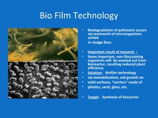
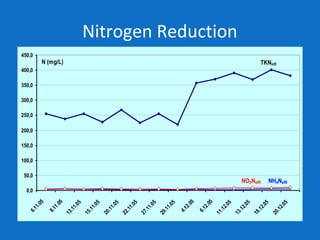
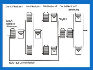
LEVAPOR – porous, adsorbing carrier for
bioprocess improvement
Dr. Imre Pascik LEVAPOR /Biofilm Tech GmbH
www. levapor.com Leverkusen, Germany
About us
• Innovative Organization
• Fixed Film Based Process Solutions
• Complex Effluent, Municipal Wastewater,
Polluted Gas
• CEO Dr. Imre Pascik
• 40 years of experience with Bayer AG,
Environmental Bio Technology Centre,
Leverkusen
About us
• Development of innovative processes
• Two Step nitrification of high Ammonia
containing effluents
• Landfill Leachate Treatment
• Bayer Tower Biology (Otto Award)
• Degradation of toxic effluents using
Anaerobic-Aerobic Processes
What We do
• Problem analysis for the treatment of high strength
industrial and municipal wastewater treatment
• Define treatment goals and conceptual process
design
• Development of optimal process and design
parameters with pilot tests
• Manufacturing of high performance tailor made bio
carriers for the application
• Process Start up
Industries We serve
• Chemicals and Pharmaceuticals
• Petrochemicals and Refineries
• Pulp and Paper
• Coal Conversion : coke plant, coal gasification,
pyrolysis
• Textile finishing and Leather manufacturers
• Municipal Wastewater Treatment
• Special effluents like land fill leachate and sludge
processing unit
Biological Removal of nitrogen
NITRIFICATION is a biological oxidation followed by
biological reduction, DENITRIFICATIONNH4
+
+1.5 O2 Nitrosomonas → NO2
-
+ 2 H+
+ H2O
ammonium pH-value decreases !
NO2
-
+ 0.5 O2 Nitrobacter → NO3
-
NITRIFICATION = NH4
+
bio-oxidation  NO3
-
NH4
+
+1.5 O2 Nitrosomonas → NO2
-
+ 2 H+
+ H2O
ammonium pH-value decreases !
NO2
-
+ 0.5 O2 Nitrobacter → NO3
-
NITRIFICATION = NH4
+
bio-oxidation  NO3
-
Nitrosomonas and Nitrobacter
Attributes of nitrifying bacteria
• slow growth: generation time: 12 to 24 hrs
• low cell yield: 3 % from N-oxidized
• weak flocculation
• high sensitivity to certain chemicals
FACTORS AFFECTING NITRIFICATION
1.SUBSTRATE – WASTE WATER MATRIX
• 2. INHIBITORS
• 3. NITRIFYING BIOMASS
• 4. PROCESS CONDITIONS
• 5. PROCESS CONCEPT
FACTORS AFFECTING NITRIFICATION
WASTE WATER MATRIX
• Organic pollutants - structure,concentr.,effect (tensides)
• COD: NH4N - ratio
• Inorganic pollutants-salinity, Ca2+
,heavy metals(Cd,Cu)
• INHIBITORS - effect (reversible, irrevers.), concentration
• QUALITY FLUCTUATIONS
BIOMASS
• Bioactivity - (gNoxidized /kgBiomass*day)
• Stability - resistance to inhibiting influences
PROCESS PARAMETERS
• Food : Mass-Ratio (gN/kgBiomass*day)
• C/N - ratio
• Temperature, pH, dissolved O2
Types of
upsets 
Biomass wash-out Disturbed process Inhibited process
Phenomena
biomass doesn´t
settle, can´t be
separated and leaves
the reactor
Lower degree of
nitrification,slower
process
Total inhibition
Bioactivity in
the reactor
Unchanged, but lower
efficiency due to lower
MLVSS in the reactor
Lower, but able to
recovery after
elimination of the
causes
No bioactivity
Possible
reasons
- biomass morphology:
bulking or small flocs
- high salinity
- deficit in nutrients
-overloaded separation
• Waste water matrix:
structure and concentration of
organic and inorganic pollutants
• Fluctuations: quality and quantity of
pollutants
• Remarkable changes of process para-
meters: pH, temperature
* plant operators
Type of the upset Possible measure
Weakly flocculating, slowly settling biomass,
wash-out
-Addition of biodegradable organic
carbon source
- Immobilisation on carrier material *
Periodical inhibition by reversible inhibitors - Temporary addition of powdered
activated carbon
- Addition of nitrifying biomass from
external plants *
Continuous inhibition by reversible acting
inhibitors
- Identification and source treatment of
the inhibitory effluent stream
- Adaptation of nitrifying biomass
- Semi-continuous addition of separately
generated nitrifying biomass *
Irreversible inhibition by strong inhibitors -New startup with external biomass
- Identification and source treatment of
inhibitory effluent streams
Bio Film Technology
• Biodegradation of pollutants occurs
via teamwork of microorganisms
united
in sludge flocs
• Important result of research :
• Some important, non-flocculating
organisms will be washed out from
bioreactor, resulting reduced plant
efficiency
• Solution: Biofilm technology
• via immobilisation, cell growth on
• solid surfaces, “carriers“ made of
• plastics, sand, glass, etc.
• Target: Synthesis of biocarrier
Our REQUESTS on OPTIMAL CARRIER
• PROPERTY EFFECT
• 1. Adsorbing capacity - binding toxic pollutants
- fast colonization + bio film
- fast start up at high level
• 2. Porosity, high inner surface - protection of the biofilm
• (high biomass content) - high space-time-yields
• 3. Fast wetting - homogenous fluidisation
• 4. Water binding - mass transport, bioactivity
• 5. Proper fluidisation - lower energy consumption
Our Technology
• LEVAPOR Bio Carrier
• First synthesized Bio Carrier
• Porous, Flexible, Durable PU foam
impregnated with surface active pigments like
activated carbon
• Due to variability of foam and pigment type
and their ratios, tailor made carriers can be
produced with varying properties
Our Technology
Properties
High Adsorbing Surface
• 10 to 12 kg of activated
carbon per m3 of foam
matrix
• PU foam surface area 2500
m2/m3
• 1000-2000 m2/g surface
area of activated carbon
• Extremely high adsorbing
surface
Benefits:
• Reversible Adsorption
• Rapid microbial colonization
and biofilm formation
• Temporary adsorption of
toxic and inhibitory
substances
• Subsequent biodegradation
and thus regeneration of
surface
Advantages
• Fixing of weakly flocculating nitrifying biomass on the carrier material
• Temporary adsorption of reversible inhibitors and their subsequent
biodegradation on activated carbon present in the carrier material . Also
reducing its toxicity in the bulk liquid and thus stabilizing process in suspended
phase
• Short process start up and higher performance compared to suspended mass
based systems (100 to 300%)
• Higher process stability against toxic shock loads and fluctuations in reactor
conditions
• Lower Degree of Filling (12 to 15%)
• Smaller foot print
• Lower energy consumption for fluidization
• Lower sludge production
• Simpler process control
Applications
• Nitrification-Denitrification of Petro Chemicals effluent
• COD removal, Nitrification of Highly toxic Agro Chemicals
effluent
• Nitrification of municipal effluent under cold climate
• Nitrification of Hyper Saline Effluent
Agro Chemicals Manufacturing
Unit
• Pesticides Manufacturing Agrochemicals industries
• A Wide variety of agro chemicals manufactured at site due
to hectic crop cycle
• Effluents Containing :
• Biologically active biocides and often inhibiting raw
chemicals , active ingredients and their by products
• Solvents like methanol, aromates, dicholoromethane,
methyl-isobutyl-ketone(MIBK) from the formulations
• Higher Salinity
A typical Effluent Characteristics
• Up to 12,000 mg/lit COD comprising solvents in it
• Up to 600 mg/lit inhibitory , active ingredients and their by
products
• 500 to 800 mg/lit Total Kjehldahl Nitrogen (TKN) containing
mostly Organic-N associated with slowly hydrolysable s-
triazine.
• Up to 1500 mg/lit Sulfates (SO4-)
• 10,000 to 25,000 mg/lit Salt Concentration as NaCl
The Problem
• Adversely affect the environment
• Presence of high amount of biodegradable solvents make wet
oxidation processes costly and thus biological degradation
would be cost effective alternative
• Higher concentrations of inhibitory substances lower the COD
removal efficiency of suspended growth only reactors
• COD removal also affected due to high fluctuations of load
• Severe nitrification inhibition due to fluctuating COD removal
efficiency
• Aerobic only treatment increases aeration costs and also
handling of high amount of toxic sludge
The solution
• MicroAerobic-Anaerobic-Aerobic
• Provides most diverse microbial consortia responsible for
the biodegradation of complex molecular structures.
• During Anaerobic Step the complex molecules are
hydrolysed
• Much of the COD removed , thus reduce aeration demand
• Lower sludge production and thus solids handling costs.
• Presence of inhibitory substances, pH changes, salinity
fluctuations cause deflocculation and wash out of microbes
• Thus, immobilization of microbes on carriers
Pilot Testing
• Proposed Micro Aerobic-Anaerobic-Aerobic
Scheme with denitrification
• Tested for two years at site
•
Pollutant Removal
Pollutant
influent
concentrations
removal %
overall in different steps
mg/L % microaerob-
+ anaerobic
aerobic
Aromatic solvents 1,5-3,0 100,0 90,0 10,0
Methanol 930 - 1980 100,0 95,0-100,0 0-5,0
Dichloromethane 4,0 - 42,0 100,0 100,0 0,0
MIBK 9,0 -330,0 100,0 76,0 24,0
Amines 56,2 - 64,8 100,0 90,0-100,0 0,0-10,0
Triazine derivatives 96,5 - 114,3 100,0 64,2 35,8
Carbamates 17,8 - 24,3 80,0 72,0 28,0
Herbicides total 154,0 - 337,0 91,5 75 25
Biodegradation of Herbicides
Component
26.10.05
Influent degree of removal,
overall
% removal in
single steps
mg/L absol. S D % MAE ANA AER
Atrazine 20,4 19,6 96,1 57,1 18,4 24,5
Simazine 1,9 1,9 100,0 57,9 10,5 31,6
Terb.Azine 14,1 13,3 94,3 51,9 34,6 13,5
Ametryn 1,7 1,7 100,0 52,9 11,8 35,3
Prometryn 1,9 1,9 100,0 47,4 31,6 21,0
Tris 12,6 11,9 90,0 52,1 31,9 16,0
Unknown 60,3 53,1 88,1 62,3 23,4 14,3
Terbutryn 1,4 1,4 100,0 42,9 28,6 28,5
Linuron 11,3 11,3 100,0 92,9 7,1
Bromacil 1,0 0,8 80,0 50,0 50,0 0,0
Dicuran 7,4 6,8 91,9 20,6 29,4 50,0
Diuron 3,2 3,2 100,0 43,8 6,3 49,9
SHerbicides 161,9 148,1 91,5 60,6 9,2 30,2
Full Scale Plant
• 1.8 MLD
• 8-12,000 mg/lit COD
• 300-600 mg/lit TKN
• 12-25,000 mg/lit
Salinity
Full Scale Plant
COD reduction
COD-removal
0%
10%
20%
30%
40%
50%
60%
70%
80%
90%
100%
2.10.055.10..058.10..0511
.10
..0519
.10
..0522
.10
.0
525
.10
.0
528
.10
.0
531
.10
.0
53.11.057.11.0510
.11
.0
513
.11
.0
516
.11
.0
519
.11
.0
522
.11
.0
525
.11
.0
528
.11
.0
51.12.054.12.057.12.0510
.12
.0
514
.12
.0
517
.12
.0
520
.12
.0
523
.12
.0
526
.12
.0
5
total
microaerobic
Nitrogen Reduction
0,0
50,0
100,0
150,0
200,0
250,0
300,0
350,0
400,0
450,0
6.11.05
8.11.05
13.11.05
15.11.05
20.11.05
22.11.05
27.11.05
29.11.05
4.12.05
6.12.05
11.12.05
13.12.05
18.12.05
20.12.05
NO3Neffl NH4Neffl
N (mg/L) TKNinfl
Plant for the biological removal of 8100 kg/d NH4
+
in the
petrochemical industry in Germany (startup: 1981)
SHELL, Wesseling 1977 :
8 mio t/yr crude oil, ethylene, methanol,carbamide,coal
gasification
Waste water situation:
• flow = 8000 m³/day
• COD = 10.800 kg/d
• NH4N = 8000 kg/d
Requirement: removal of COD + NH4N( < 15 mg/L)
No experience with nitrification/denitrification of N-rich
effluents !
Several contractors refused the project
Existing pretreatment: API-separator + flotation
SHELL-PLANT – Wesseling, Germany
It was the first plant of this type and capacity in the world
Footprint: 11.000 m² surface instead of 50.000 m² for basin
construction
Daily oxygene uptake: 45.000 kg/d
Injector aeration : 10.800 m³/h air instead of 70.000 m³/h
(surface aerators)
Startup in July 1981
DUE TO NUMEROUS INFLUENCING FACTORS FOR THE DESIGN OF TREATMENT
PLANTS WITH NITRIFICATION, BIOKINETIC PARAMETERS OF THE PROCES
MUST BE DETERMINED EXPERI-MENTALLY.
In lab scale plants
• degree of N-oxidation
• velocity of nitrification
• optimal F:M-ratio
• effect of peak loadings
• effect of inhibitors
can be determined, while
On-line pilot tests serve for
• confirming of process
under practical conditions
• fine optimisation
• demonstration of
technique
• staff education and
training
How Can We Associate
• Problem analysis for the treatment of high ammonia
containing effluents
• Define treatment goals and conceptual process
design
• Development of optimal process and parameters
• Manufacturing of high performance tailor made bio
carriers for the application
• Process Start up
Thank You !!!!

Nitrification of Complex Effluent

  • 1.
    LEVAPOR – porous,adsorbing carrier for bioprocess improvement Dr. Imre Pascik LEVAPOR /Biofilm Tech GmbH www. levapor.com Leverkusen, Germany
  • 2.
    About us • InnovativeOrganization • Fixed Film Based Process Solutions • Complex Effluent, Municipal Wastewater, Polluted Gas • CEO Dr. Imre Pascik • 40 years of experience with Bayer AG, Environmental Bio Technology Centre, Leverkusen
  • 3.
    About us • Developmentof innovative processes • Two Step nitrification of high Ammonia containing effluents • Landfill Leachate Treatment • Bayer Tower Biology (Otto Award) • Degradation of toxic effluents using Anaerobic-Aerobic Processes
  • 4.
    What We do •Problem analysis for the treatment of high strength industrial and municipal wastewater treatment • Define treatment goals and conceptual process design • Development of optimal process and design parameters with pilot tests • Manufacturing of high performance tailor made bio carriers for the application • Process Start up
  • 5.
    Industries We serve •Chemicals and Pharmaceuticals • Petrochemicals and Refineries • Pulp and Paper • Coal Conversion : coke plant, coal gasification, pyrolysis • Textile finishing and Leather manufacturers • Municipal Wastewater Treatment • Special effluents like land fill leachate and sludge processing unit
  • 6.
    Biological Removal ofnitrogen NITRIFICATION is a biological oxidation followed by biological reduction, DENITRIFICATIONNH4 + +1.5 O2 Nitrosomonas → NO2 - + 2 H+ + H2O ammonium pH-value decreases ! NO2 - + 0.5 O2 Nitrobacter → NO3 - NITRIFICATION = NH4 + bio-oxidation  NO3 - NH4 + +1.5 O2 Nitrosomonas → NO2 - + 2 H+ + H2O ammonium pH-value decreases ! NO2 - + 0.5 O2 Nitrobacter → NO3 - NITRIFICATION = NH4 + bio-oxidation  NO3 -
  • 7.
    Nitrosomonas and Nitrobacter Attributesof nitrifying bacteria • slow growth: generation time: 12 to 24 hrs • low cell yield: 3 % from N-oxidized • weak flocculation • high sensitivity to certain chemicals
  • 8.
    FACTORS AFFECTING NITRIFICATION 1.SUBSTRATE– WASTE WATER MATRIX • 2. INHIBITORS • 3. NITRIFYING BIOMASS • 4. PROCESS CONDITIONS • 5. PROCESS CONCEPT
  • 9.
    FACTORS AFFECTING NITRIFICATION WASTEWATER MATRIX • Organic pollutants - structure,concentr.,effect (tensides) • COD: NH4N - ratio • Inorganic pollutants-salinity, Ca2+ ,heavy metals(Cd,Cu) • INHIBITORS - effect (reversible, irrevers.), concentration • QUALITY FLUCTUATIONS BIOMASS • Bioactivity - (gNoxidized /kgBiomass*day) • Stability - resistance to inhibiting influences PROCESS PARAMETERS • Food : Mass-Ratio (gN/kgBiomass*day) • C/N - ratio • Temperature, pH, dissolved O2
  • 10.
    Types of upsets  Biomasswash-out Disturbed process Inhibited process Phenomena biomass doesn´t settle, can´t be separated and leaves the reactor Lower degree of nitrification,slower process Total inhibition Bioactivity in the reactor Unchanged, but lower efficiency due to lower MLVSS in the reactor Lower, but able to recovery after elimination of the causes No bioactivity Possible reasons - biomass morphology: bulking or small flocs - high salinity - deficit in nutrients -overloaded separation • Waste water matrix: structure and concentration of organic and inorganic pollutants • Fluctuations: quality and quantity of pollutants • Remarkable changes of process para- meters: pH, temperature * plant operators
  • 11.
    Type of theupset Possible measure Weakly flocculating, slowly settling biomass, wash-out -Addition of biodegradable organic carbon source - Immobilisation on carrier material * Periodical inhibition by reversible inhibitors - Temporary addition of powdered activated carbon - Addition of nitrifying biomass from external plants * Continuous inhibition by reversible acting inhibitors - Identification and source treatment of the inhibitory effluent stream - Adaptation of nitrifying biomass - Semi-continuous addition of separately generated nitrifying biomass * Irreversible inhibition by strong inhibitors -New startup with external biomass - Identification and source treatment of inhibitory effluent streams
  • 12.
    Bio Film Technology •Biodegradation of pollutants occurs via teamwork of microorganisms united in sludge flocs • Important result of research : • Some important, non-flocculating organisms will be washed out from bioreactor, resulting reduced plant efficiency • Solution: Biofilm technology • via immobilisation, cell growth on • solid surfaces, “carriers“ made of • plastics, sand, glass, etc. • Target: Synthesis of biocarrier
  • 13.
    Our REQUESTS onOPTIMAL CARRIER • PROPERTY EFFECT • 1. Adsorbing capacity - binding toxic pollutants - fast colonization + bio film - fast start up at high level • 2. Porosity, high inner surface - protection of the biofilm • (high biomass content) - high space-time-yields • 3. Fast wetting - homogenous fluidisation • 4. Water binding - mass transport, bioactivity • 5. Proper fluidisation - lower energy consumption
  • 14.
    Our Technology • LEVAPORBio Carrier • First synthesized Bio Carrier • Porous, Flexible, Durable PU foam impregnated with surface active pigments like activated carbon • Due to variability of foam and pigment type and their ratios, tailor made carriers can be produced with varying properties
  • 15.
  • 16.
    Properties High Adsorbing Surface •10 to 12 kg of activated carbon per m3 of foam matrix • PU foam surface area 2500 m2/m3 • 1000-2000 m2/g surface area of activated carbon • Extremely high adsorbing surface Benefits: • Reversible Adsorption • Rapid microbial colonization and biofilm formation • Temporary adsorption of toxic and inhibitory substances • Subsequent biodegradation and thus regeneration of surface
  • 17.
    Advantages • Fixing ofweakly flocculating nitrifying biomass on the carrier material • Temporary adsorption of reversible inhibitors and their subsequent biodegradation on activated carbon present in the carrier material . Also reducing its toxicity in the bulk liquid and thus stabilizing process in suspended phase • Short process start up and higher performance compared to suspended mass based systems (100 to 300%) • Higher process stability against toxic shock loads and fluctuations in reactor conditions • Lower Degree of Filling (12 to 15%) • Smaller foot print • Lower energy consumption for fluidization • Lower sludge production • Simpler process control
  • 18.
    Applications • Nitrification-Denitrification ofPetro Chemicals effluent • COD removal, Nitrification of Highly toxic Agro Chemicals effluent • Nitrification of municipal effluent under cold climate • Nitrification of Hyper Saline Effluent
  • 19.
    Agro Chemicals Manufacturing Unit •Pesticides Manufacturing Agrochemicals industries • A Wide variety of agro chemicals manufactured at site due to hectic crop cycle • Effluents Containing : • Biologically active biocides and often inhibiting raw chemicals , active ingredients and their by products • Solvents like methanol, aromates, dicholoromethane, methyl-isobutyl-ketone(MIBK) from the formulations • Higher Salinity
  • 20.
    A typical EffluentCharacteristics • Up to 12,000 mg/lit COD comprising solvents in it • Up to 600 mg/lit inhibitory , active ingredients and their by products • 500 to 800 mg/lit Total Kjehldahl Nitrogen (TKN) containing mostly Organic-N associated with slowly hydrolysable s- triazine. • Up to 1500 mg/lit Sulfates (SO4-) • 10,000 to 25,000 mg/lit Salt Concentration as NaCl
  • 21.
    The Problem • Adverselyaffect the environment • Presence of high amount of biodegradable solvents make wet oxidation processes costly and thus biological degradation would be cost effective alternative • Higher concentrations of inhibitory substances lower the COD removal efficiency of suspended growth only reactors • COD removal also affected due to high fluctuations of load • Severe nitrification inhibition due to fluctuating COD removal efficiency • Aerobic only treatment increases aeration costs and also handling of high amount of toxic sludge
  • 22.
    The solution • MicroAerobic-Anaerobic-Aerobic •Provides most diverse microbial consortia responsible for the biodegradation of complex molecular structures. • During Anaerobic Step the complex molecules are hydrolysed • Much of the COD removed , thus reduce aeration demand • Lower sludge production and thus solids handling costs. • Presence of inhibitory substances, pH changes, salinity fluctuations cause deflocculation and wash out of microbes • Thus, immobilization of microbes on carriers
  • 23.
    Pilot Testing • ProposedMicro Aerobic-Anaerobic-Aerobic Scheme with denitrification • Tested for two years at site •
  • 24.
    Pollutant Removal Pollutant influent concentrations removal % overallin different steps mg/L % microaerob- + anaerobic aerobic Aromatic solvents 1,5-3,0 100,0 90,0 10,0 Methanol 930 - 1980 100,0 95,0-100,0 0-5,0 Dichloromethane 4,0 - 42,0 100,0 100,0 0,0 MIBK 9,0 -330,0 100,0 76,0 24,0 Amines 56,2 - 64,8 100,0 90,0-100,0 0,0-10,0 Triazine derivatives 96,5 - 114,3 100,0 64,2 35,8 Carbamates 17,8 - 24,3 80,0 72,0 28,0 Herbicides total 154,0 - 337,0 91,5 75 25
  • 25.
    Biodegradation of Herbicides Component 26.10.05 Influentdegree of removal, overall % removal in single steps mg/L absol. S D % MAE ANA AER Atrazine 20,4 19,6 96,1 57,1 18,4 24,5 Simazine 1,9 1,9 100,0 57,9 10,5 31,6 Terb.Azine 14,1 13,3 94,3 51,9 34,6 13,5 Ametryn 1,7 1,7 100,0 52,9 11,8 35,3 Prometryn 1,9 1,9 100,0 47,4 31,6 21,0 Tris 12,6 11,9 90,0 52,1 31,9 16,0 Unknown 60,3 53,1 88,1 62,3 23,4 14,3 Terbutryn 1,4 1,4 100,0 42,9 28,6 28,5 Linuron 11,3 11,3 100,0 92,9 7,1 Bromacil 1,0 0,8 80,0 50,0 50,0 0,0 Dicuran 7,4 6,8 91,9 20,6 29,4 50,0 Diuron 3,2 3,2 100,0 43,8 6,3 49,9 SHerbicides 161,9 148,1 91,5 60,6 9,2 30,2
  • 26.
    Full Scale Plant •1.8 MLD • 8-12,000 mg/lit COD • 300-600 mg/lit TKN • 12-25,000 mg/lit Salinity
  • 27.
  • 28.
  • 29.
  • 30.
    Plant for thebiological removal of 8100 kg/d NH4 + in the petrochemical industry in Germany (startup: 1981)
  • 31.
    SHELL, Wesseling 1977: 8 mio t/yr crude oil, ethylene, methanol,carbamide,coal gasification Waste water situation: • flow = 8000 m³/day • COD = 10.800 kg/d • NH4N = 8000 kg/d Requirement: removal of COD + NH4N( < 15 mg/L) No experience with nitrification/denitrification of N-rich effluents ! Several contractors refused the project Existing pretreatment: API-separator + flotation
  • 32.
    SHELL-PLANT – Wesseling,Germany It was the first plant of this type and capacity in the world Footprint: 11.000 m² surface instead of 50.000 m² for basin construction Daily oxygene uptake: 45.000 kg/d Injector aeration : 10.800 m³/h air instead of 70.000 m³/h (surface aerators) Startup in July 1981
  • 35.
    DUE TO NUMEROUSINFLUENCING FACTORS FOR THE DESIGN OF TREATMENT PLANTS WITH NITRIFICATION, BIOKINETIC PARAMETERS OF THE PROCES MUST BE DETERMINED EXPERI-MENTALLY. In lab scale plants • degree of N-oxidation • velocity of nitrification • optimal F:M-ratio • effect of peak loadings • effect of inhibitors can be determined, while
  • 36.
    On-line pilot testsserve for • confirming of process under practical conditions • fine optimisation • demonstration of technique • staff education and training
  • 37.
    How Can WeAssociate • Problem analysis for the treatment of high ammonia containing effluents • Define treatment goals and conceptual process design • Development of optimal process and parameters • Manufacturing of high performance tailor made bio carriers for the application • Process Start up
  • 38.