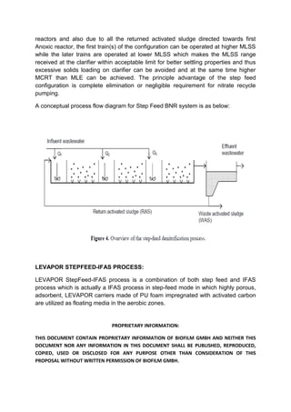
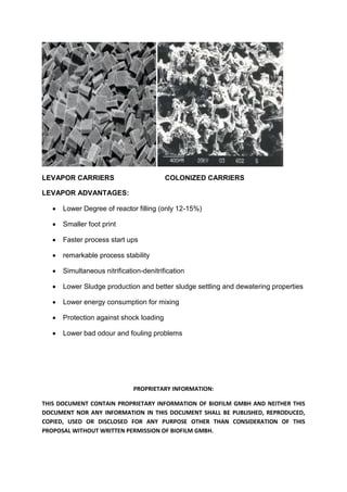
PROPRIETARY INFORMATION:
THIS DOCUMENT CONTAIN PROPRIETARY INFORMATION OF BIOFILM GMBH AND NEITHER THIS
DOCUMENT NOR ANY INFORMATION IN THIS DOCUMENT SHALL BE PUBLISHED, REPRODUCED,
COPIED, USED OR DISCLOSED FOR ANY PURPOSE OTHER THAN CONSIDERATION OF THIS
PROPOSAL WITHOUT WRITTEN PERMISSION OF BIOFILM GMBH.
LEVAPOR
STEP FEED- IFAS PROCESS
Contact: Dr. Imre Pascik : levapor@web.de
Amit Christian: levapor.india@gmail.com
PROPRIETARY INFORMATION:
THIS DOCUMENT CONTAIN PROPRIETARY INFORMATION OF BIOFILM GMBH AND NEITHER THIS
DOCUMENT NOR ANY INFORMATION IN THIS DOCUMENT SHALL BE PUBLISHED, REPRODUCED,
COPIED, USED OR DISCLOSED FOR ANY PURPOSE OTHER THAN CONSIDERATION OF THIS
PROPOSAL WITHOUT WRITTEN PERMISSION OF BIOFILM GMBH.
LEVAPOR StepFeed- IFAS Process:
Levapor Step-Feed IFAS process is based on proprietary porous, adsorbing PU
carriers impregnated with activated carbon and surface active pigments for high
adsorbent capacity and high internal porosity with extremely large surface are for
optimal growth of micro organisms for biological wastewater treatment.
The process combines step feed activated sludge process with IFAS which offers
inherent advantages of both the process along with bringing advantages of hybrid
suspended growth and attached growth processes to achieve higher level of BNR
with reduced foot print and better process resiliency against toxic shock loads and
flow variations.
PROCESS APPLICATION:
The LEVAPOR STEP-FFED IFAS process can be applied to various biological
wastewater treatment applications:
 Upgradation of existing BOD removal plant to BNR for achieving
BOD/TSS/TN < 10 ppm
 New BNR Sewage Treatment plant
HOW IT WORKS:
IFAS, Integrated Fixed Film Activated Sludge (IFAS) also known as CFAS
(Combined Fixed Film Activated Sludge) process is a combination of two
fundamental biological wastewater treatment technologies namely fixed film growth
and suspended growth technology.
In the IFAS/CFAS process, fixed film media/carriers are added to the conventional
activated sludge system aeration tank which allows growth of biomass on it. The
growth of micro organisms on the attached phase enables significant increase in the
biomass in the aeration tank increasing the SRT of the system without increase of
recycled sludge flow rate.
PROPRIETARY INFORMATION:
THIS DOCUMENT CONTAIN PROPRIETARY INFORMATION OF BIOFILM GMBH AND NEITHER THIS
DOCUMENT NOR ANY INFORMATION IN THIS DOCUMENT SHALL BE PUBLISHED, REPRODUCED,
COPIED, USED OR DISCLOSED FOR ANY PURPOSE OTHER THAN CONSIDERATION OF THIS
PROPOSAL WITHOUT WRITTEN PERMISSION OF BIOFILM GMBH.
This hybrid configuration of suspended as well as attached growth technologies
combines distinct advantages of both the technologies which are:
 Retention of higher biomass in the system rendering higher loading rates and
improved process stability
 Smaller foot print
 Lower sludge production compared to suspended growth only system
 Improved settling characteristics of sludge
 Lower solids loading rate to secondary clarifiers and thus improving their
performance and operation
 Improved process recovery from upsets
TRADITIONAL MLE (Modified Ludzack-Ettinger ) Process for BNR:
MLE is the most popular configuration of BNR process in which Nitrates produced
during the Aerobic phase are recycled back to the Anoxic reactor place upstream of
the Aerobic reactor where the generated Nitrates are denitrified under Anoxic
conditions with the help of facultative heterotrophs brought with the Return Activated
Sludge (RAS) stream. An MLE process requires both RAS pumping as well as
Nitrate Recycle Flow which is termed as Internal Recycle (IR). From the process
control point of view it is one of the simple process configurations. To avoid
excessive hydraulic loading of the clarifier the IR flow is taken from the aeration tank
effluent weir and before the clarifier inlet. At times, to avoid over sizing and hydraulic
loading on the retention screens and effluent weir, the IR pumps are installed inside
the Aeration Tank close to the effluent weir but before retention screens so that the
hydraulic capacity required for the retention screen and effluent weir is reduced.
A conceptual process flow diagram for the MLE Process is as below:
PROPRIETARY INFORMATION:
THIS DOCUMENT CONTAIN PROPRIETARY INFORMATION OF BIOFILM GMBH AND NEITHER THIS
DOCUMENT NOR ANY INFORMATION IN THIS DOCUMENT SHALL BE PUBLISHED, REPRODUCED,
COPIED, USED OR DISCLOSED FOR ANY PURPOSE OTHER THAN CONSIDERATION OF THIS
PROPOSAL WITHOUT WRITTEN PERMISSION OF BIOFILM GMBH.
However, there are certain disadvantages of MLE configuration:
 Requires high level of Nitrate Recycle flow which increases the plant power
consumption
 Management of readily available substrate for Denitrifying bacteria is
challenging task especially when the substrate varies in the influent a lot
STEP-FEED BNR PROCESS:
Due to the high amount of Nitrate recycle required for the MLE process and also
associated issues of meeting substrate requirements for the denitrification, another
alternative for achieving same results would be step feed Anoxic-Oxic configuration
of BNR removal process in which a series of Anoxic-Aerobic reactors are
incorporated in the design and operated in series. The inlet wastewater is fed to the
Anoxic reactor in proportion desired which meets the substrate requirement for the
denitrification of the nitrates in the incoming wastewater from the Aerobic Reactor of
the previous stage. Due to the distribution of the inlet waste water among different
PROPRIETARY INFORMATION:
THIS DOCUMENT CONTAIN PROPRIETARY INFORMATION OF BIOFILM GMBH AND NEITHER THIS
DOCUMENT NOR ANY INFORMATION IN THIS DOCUMENT SHALL BE PUBLISHED, REPRODUCED,
COPIED, USED OR DISCLOSED FOR ANY PURPOSE OTHER THAN CONSIDERATION OF THIS
PROPOSAL WITHOUT WRITTEN PERMISSION OF BIOFILM GMBH.
reactors and also due to all the returned activated sludge directed towards first
Anoxic reactor, the first train(s) of the configuration can be operated at higher MLSS
while the later trains are operated at lower MLSS which makes the MLSS range
received at the clarifier within acceptable limit for better settling properties and thus
excessive solids loading on clarifier can be avoided and at the same time higher
MCRT than MLE can be achieved. The principle advantage of the step feed
configuration is complete elimination or negligible requirement for nitrate recycle
pumping.
A conceptual process flow diagram for Step Feed BNR system is as below:
LEVAPOR STEPFEED-IFAS PROCESS:
LEVAPOR StepFeed-IFAS process is a combination of both step feed and IFAS
process which is actually a IFAS process in step-feed mode in which highly porous,
adsorbent, LEVAPOR carriers made of PU foam impregnated with activated carbon
are utilized as floating media in the aerobic zones.
PROPRIETARY INFORMATION:
THIS DOCUMENT CONTAIN PROPRIETARY INFORMATION OF BIOFILM GMBH AND NEITHER THIS
DOCUMENT NOR ANY INFORMATION IN THIS DOCUMENT SHALL BE PUBLISHED, REPRODUCED,
COPIED, USED OR DISCLOSED FOR ANY PURPOSE OTHER THAN CONSIDERATION OF THIS
PROPOSAL WITHOUT WRITTEN PERMISSION OF BIOFILM GMBH.
Due to fine pore structure of LEVAPOR carriers, it is feasible to operate the Aerobic
IFAS zones at higher MLSS concentration and achieve highly stable nitrification and
BOD removal. The anoxic zones developed due to high internal porosity and higher
substrate gradient also helps to achieve higher level of simultaneous nitrification and
denitrification which further reduces the Anoxic zone foot print and thus higher level
of Total Nitrogen removal efficiencies can be achieved.
Specific Advantages offered by LEVAPOR StepFeed-IFAS Process are as follows:
 Reduced foot print and thus upgradation of existing plants to BNR feasible
with higher flows and higher loading
 Remarkable process stability
 Lower foot print
 Elimination of Nitrate recycle and thus huge power saving
 Higher MCRT and MLSS in early compartments without affecting the solids
loading to clarifiers
 Flows can be split between different compartments based on organic loading
and denitrification substrate requirement offering better organic/flow loading
management along with better utilization of substrate for denitrification
LEVAPOR TECHNOLOGY:
The LEVAPOR STEPFEED-IFAS technology offers economical, efficient, compact
and most resilient biological wastewater treatment process solutions for plant up
gradation, nitrogen removal and wastewater reuse.
Carrier adsorbent capacity, higher internal porosity, higher wetting and fluidization
properties along with lower weight are critical to achieve faster colonization,
protection of biomass, higher mass transfer, better mixing and homogenization
capacity and reduced energy consumption.
Our unique carriers made of flexible, durable, porous, light weight PU foam
impregnated with activated carbon have been designed to achieve these properties
for optimal performance of biological processes.
PROPRIETARY INFORMATION:
THIS DOCUMENT CONTAIN PROPRIETARY INFORMATION OF BIOFILM GMBH AND NEITHER THIS
DOCUMENT NOR ANY INFORMATION IN THIS DOCUMENT SHALL BE PUBLISHED, REPRODUCED,
COPIED, USED OR DISCLOSED FOR ANY PURPOSE OTHER THAN CONSIDERATION OF THIS
PROPOSAL WITHOUT WRITTEN PERMISSION OF BIOFILM GMBH.
PRINCIPLE CHARACTERISTICS:
 LEVAPOR carriers were developed to produce optimal conditions for the
growth of specific micro organisms responsible for efficient removal of
pollutants achieving higher removal rates with smaller foot prints.
 The combination of optimum properties achieved through impregnation of PU
foam matrix with activated carbon along with surface active pigments makes
LEVAPOR carriers the most suitable carriers for MBBR/IFAS application.
 A cuboid configuration of 20X 20 X 7 mm allows flexibility to use sieves of
higher sizes (6-7 mm) preventing head loss in the system. Moreover, light
weight of colonized carriers (65-80 kg/m3) compared to plastic media reduces
mixing energy requirement drastically offering significant energy savings.
 The hydrophilic nature of PU foam renders fast wetting properties and higher
fluidization capacity allowing for better homogenization and optimal mass
transfer efficiencies of substrate and nutrients across the PU carrier matrix.
 The impregnation of activated carbon allows for adsorption of toxic and
inhibitory substances on it which provides remarkable process stability against
toxic shock loadings and also minimizes bad odour and fouling problems
drastically. The impregnation also facilitates faster colonization of carrier
material reducing start up times for processes.
 High internal porosity of PU carriers makes the process highly resilient to flow
and pollutant loading variations protecting biomass against adverse
conditions.
PROPRIETARY INFORMATION:
THIS DOCUMENT CONTAIN PROPRIETARY INFORMATION OF BIOFILM GMBH AND NEITHER THIS
DOCUMENT NOR ANY INFORMATION IN THIS DOCUMENT SHALL BE PUBLISHED, REPRODUCED,
COPIED, USED OR DISCLOSED FOR ANY PURPOSE OTHER THAN CONSIDERATION OF THIS
PROPOSAL WITHOUT WRITTEN PERMISSION OF BIOFILM GMBH.
LEVAPOR CARRIERS COLONIZED CARRIERS
LEVAPOR ADVANTAGES:
 Lower Degree of reactor filling (only 12-15%)
 Smaller foot print
 Faster process start ups
 remarkable process stability
 Simultaneous nitrification-denitrification
 Lower Sludge production and better sludge settling and dewatering properties
 Lower energy consumption for mixing
 Protection against shock loading
 Lower bad odour and fouling problems
PROPRIETARY INFORMATION:
THIS DOCUMENT CONTAIN PROPRIETARY INFORMATION OF BIOFILM GMBH AND NEITHER THIS
DOCUMENT NOR ANY INFORMATION IN THIS DOCUMENT SHALL BE PUBLISHED, REPRODUCED,
COPIED, USED OR DISCLOSED FOR ANY PURPOSE OTHER THAN CONSIDERATION OF THIS
PROPOSAL WITHOUT WRITTEN PERMISSION OF BIOFILM GMBH.
COMPARISON DIFFERENT CARRIER MATERIALS
Property LEVAPOR Unmodified PUR-foam Plastic carriers
total surface (m²/m³) up to 20,000 up to 2500 300 to 1200
adsorbing capacity very high moderate low
required degree of reactor filling 12 to 15 % 20 to 40 % 30 to 70 %
porosity 75 to 90 % 75 to 90 % 50 – 75 %
wetting immediately / 1- 3 days up to 3 months months (after colonisation)
water uptake up to 250 % - remarkably lower - negligible
ionic charge + to - - non variable no
colonisation by microbes 60 to 90 min. - several weeks several weeks to months
full fluidization at gas upflow 4 to 7 (m³/m²xh) n.d. via coars bubble aeration
carrier retention 8-10 mm sieves 8-10 mm sieves screens
aeration fine bubble aeration fine bubble aeration coarse bubble
additional energy for fluidization not required required ( > 20-25% filling) because of coarse bubbles
excess sludge removal by fluidization n.d. by fluidization
variability of properties very variable quite narrow negligible

LEVAPOR STEPFEED-IFAS PROCESS FOR BNR

  • 1.
    PROPRIETARY INFORMATION: THIS DOCUMENTCONTAIN PROPRIETARY INFORMATION OF BIOFILM GMBH AND NEITHER THIS DOCUMENT NOR ANY INFORMATION IN THIS DOCUMENT SHALL BE PUBLISHED, REPRODUCED, COPIED, USED OR DISCLOSED FOR ANY PURPOSE OTHER THAN CONSIDERATION OF THIS PROPOSAL WITHOUT WRITTEN PERMISSION OF BIOFILM GMBH. LEVAPOR STEP FEED- IFAS PROCESS Contact: Dr. Imre Pascik : levapor@web.de Amit Christian: levapor.india@gmail.com
  • 2.
    PROPRIETARY INFORMATION: THIS DOCUMENTCONTAIN PROPRIETARY INFORMATION OF BIOFILM GMBH AND NEITHER THIS DOCUMENT NOR ANY INFORMATION IN THIS DOCUMENT SHALL BE PUBLISHED, REPRODUCED, COPIED, USED OR DISCLOSED FOR ANY PURPOSE OTHER THAN CONSIDERATION OF THIS PROPOSAL WITHOUT WRITTEN PERMISSION OF BIOFILM GMBH. LEVAPOR StepFeed- IFAS Process: Levapor Step-Feed IFAS process is based on proprietary porous, adsorbing PU carriers impregnated with activated carbon and surface active pigments for high adsorbent capacity and high internal porosity with extremely large surface are for optimal growth of micro organisms for biological wastewater treatment. The process combines step feed activated sludge process with IFAS which offers inherent advantages of both the process along with bringing advantages of hybrid suspended growth and attached growth processes to achieve higher level of BNR with reduced foot print and better process resiliency against toxic shock loads and flow variations. PROCESS APPLICATION: The LEVAPOR STEP-FFED IFAS process can be applied to various biological wastewater treatment applications:  Upgradation of existing BOD removal plant to BNR for achieving BOD/TSS/TN < 10 ppm  New BNR Sewage Treatment plant HOW IT WORKS: IFAS, Integrated Fixed Film Activated Sludge (IFAS) also known as CFAS (Combined Fixed Film Activated Sludge) process is a combination of two fundamental biological wastewater treatment technologies namely fixed film growth and suspended growth technology. In the IFAS/CFAS process, fixed film media/carriers are added to the conventional activated sludge system aeration tank which allows growth of biomass on it. The growth of micro organisms on the attached phase enables significant increase in the biomass in the aeration tank increasing the SRT of the system without increase of recycled sludge flow rate.
  • 3.
    PROPRIETARY INFORMATION: THIS DOCUMENTCONTAIN PROPRIETARY INFORMATION OF BIOFILM GMBH AND NEITHER THIS DOCUMENT NOR ANY INFORMATION IN THIS DOCUMENT SHALL BE PUBLISHED, REPRODUCED, COPIED, USED OR DISCLOSED FOR ANY PURPOSE OTHER THAN CONSIDERATION OF THIS PROPOSAL WITHOUT WRITTEN PERMISSION OF BIOFILM GMBH. This hybrid configuration of suspended as well as attached growth technologies combines distinct advantages of both the technologies which are:  Retention of higher biomass in the system rendering higher loading rates and improved process stability  Smaller foot print  Lower sludge production compared to suspended growth only system  Improved settling characteristics of sludge  Lower solids loading rate to secondary clarifiers and thus improving their performance and operation  Improved process recovery from upsets TRADITIONAL MLE (Modified Ludzack-Ettinger ) Process for BNR: MLE is the most popular configuration of BNR process in which Nitrates produced during the Aerobic phase are recycled back to the Anoxic reactor place upstream of the Aerobic reactor where the generated Nitrates are denitrified under Anoxic conditions with the help of facultative heterotrophs brought with the Return Activated Sludge (RAS) stream. An MLE process requires both RAS pumping as well as Nitrate Recycle Flow which is termed as Internal Recycle (IR). From the process control point of view it is one of the simple process configurations. To avoid excessive hydraulic loading of the clarifier the IR flow is taken from the aeration tank effluent weir and before the clarifier inlet. At times, to avoid over sizing and hydraulic loading on the retention screens and effluent weir, the IR pumps are installed inside the Aeration Tank close to the effluent weir but before retention screens so that the hydraulic capacity required for the retention screen and effluent weir is reduced. A conceptual process flow diagram for the MLE Process is as below:
  • 4.
    PROPRIETARY INFORMATION: THIS DOCUMENTCONTAIN PROPRIETARY INFORMATION OF BIOFILM GMBH AND NEITHER THIS DOCUMENT NOR ANY INFORMATION IN THIS DOCUMENT SHALL BE PUBLISHED, REPRODUCED, COPIED, USED OR DISCLOSED FOR ANY PURPOSE OTHER THAN CONSIDERATION OF THIS PROPOSAL WITHOUT WRITTEN PERMISSION OF BIOFILM GMBH. However, there are certain disadvantages of MLE configuration:  Requires high level of Nitrate Recycle flow which increases the plant power consumption  Management of readily available substrate for Denitrifying bacteria is challenging task especially when the substrate varies in the influent a lot STEP-FEED BNR PROCESS: Due to the high amount of Nitrate recycle required for the MLE process and also associated issues of meeting substrate requirements for the denitrification, another alternative for achieving same results would be step feed Anoxic-Oxic configuration of BNR removal process in which a series of Anoxic-Aerobic reactors are incorporated in the design and operated in series. The inlet wastewater is fed to the Anoxic reactor in proportion desired which meets the substrate requirement for the denitrification of the nitrates in the incoming wastewater from the Aerobic Reactor of the previous stage. Due to the distribution of the inlet waste water among different
  • 5.
    PROPRIETARY INFORMATION: THIS DOCUMENTCONTAIN PROPRIETARY INFORMATION OF BIOFILM GMBH AND NEITHER THIS DOCUMENT NOR ANY INFORMATION IN THIS DOCUMENT SHALL BE PUBLISHED, REPRODUCED, COPIED, USED OR DISCLOSED FOR ANY PURPOSE OTHER THAN CONSIDERATION OF THIS PROPOSAL WITHOUT WRITTEN PERMISSION OF BIOFILM GMBH. reactors and also due to all the returned activated sludge directed towards first Anoxic reactor, the first train(s) of the configuration can be operated at higher MLSS while the later trains are operated at lower MLSS which makes the MLSS range received at the clarifier within acceptable limit for better settling properties and thus excessive solids loading on clarifier can be avoided and at the same time higher MCRT than MLE can be achieved. The principle advantage of the step feed configuration is complete elimination or negligible requirement for nitrate recycle pumping. A conceptual process flow diagram for Step Feed BNR system is as below: LEVAPOR STEPFEED-IFAS PROCESS: LEVAPOR StepFeed-IFAS process is a combination of both step feed and IFAS process which is actually a IFAS process in step-feed mode in which highly porous, adsorbent, LEVAPOR carriers made of PU foam impregnated with activated carbon are utilized as floating media in the aerobic zones.
  • 6.
    PROPRIETARY INFORMATION: THIS DOCUMENTCONTAIN PROPRIETARY INFORMATION OF BIOFILM GMBH AND NEITHER THIS DOCUMENT NOR ANY INFORMATION IN THIS DOCUMENT SHALL BE PUBLISHED, REPRODUCED, COPIED, USED OR DISCLOSED FOR ANY PURPOSE OTHER THAN CONSIDERATION OF THIS PROPOSAL WITHOUT WRITTEN PERMISSION OF BIOFILM GMBH. Due to fine pore structure of LEVAPOR carriers, it is feasible to operate the Aerobic IFAS zones at higher MLSS concentration and achieve highly stable nitrification and BOD removal. The anoxic zones developed due to high internal porosity and higher substrate gradient also helps to achieve higher level of simultaneous nitrification and denitrification which further reduces the Anoxic zone foot print and thus higher level of Total Nitrogen removal efficiencies can be achieved. Specific Advantages offered by LEVAPOR StepFeed-IFAS Process are as follows:  Reduced foot print and thus upgradation of existing plants to BNR feasible with higher flows and higher loading  Remarkable process stability  Lower foot print  Elimination of Nitrate recycle and thus huge power saving  Higher MCRT and MLSS in early compartments without affecting the solids loading to clarifiers  Flows can be split between different compartments based on organic loading and denitrification substrate requirement offering better organic/flow loading management along with better utilization of substrate for denitrification LEVAPOR TECHNOLOGY: The LEVAPOR STEPFEED-IFAS technology offers economical, efficient, compact and most resilient biological wastewater treatment process solutions for plant up gradation, nitrogen removal and wastewater reuse. Carrier adsorbent capacity, higher internal porosity, higher wetting and fluidization properties along with lower weight are critical to achieve faster colonization, protection of biomass, higher mass transfer, better mixing and homogenization capacity and reduced energy consumption. Our unique carriers made of flexible, durable, porous, light weight PU foam impregnated with activated carbon have been designed to achieve these properties for optimal performance of biological processes.
  • 7.
    PROPRIETARY INFORMATION: THIS DOCUMENTCONTAIN PROPRIETARY INFORMATION OF BIOFILM GMBH AND NEITHER THIS DOCUMENT NOR ANY INFORMATION IN THIS DOCUMENT SHALL BE PUBLISHED, REPRODUCED, COPIED, USED OR DISCLOSED FOR ANY PURPOSE OTHER THAN CONSIDERATION OF THIS PROPOSAL WITHOUT WRITTEN PERMISSION OF BIOFILM GMBH. PRINCIPLE CHARACTERISTICS:  LEVAPOR carriers were developed to produce optimal conditions for the growth of specific micro organisms responsible for efficient removal of pollutants achieving higher removal rates with smaller foot prints.  The combination of optimum properties achieved through impregnation of PU foam matrix with activated carbon along with surface active pigments makes LEVAPOR carriers the most suitable carriers for MBBR/IFAS application.  A cuboid configuration of 20X 20 X 7 mm allows flexibility to use sieves of higher sizes (6-7 mm) preventing head loss in the system. Moreover, light weight of colonized carriers (65-80 kg/m3) compared to plastic media reduces mixing energy requirement drastically offering significant energy savings.  The hydrophilic nature of PU foam renders fast wetting properties and higher fluidization capacity allowing for better homogenization and optimal mass transfer efficiencies of substrate and nutrients across the PU carrier matrix.  The impregnation of activated carbon allows for adsorption of toxic and inhibitory substances on it which provides remarkable process stability against toxic shock loadings and also minimizes bad odour and fouling problems drastically. The impregnation also facilitates faster colonization of carrier material reducing start up times for processes.  High internal porosity of PU carriers makes the process highly resilient to flow and pollutant loading variations protecting biomass against adverse conditions.
  • 8.
    PROPRIETARY INFORMATION: THIS DOCUMENTCONTAIN PROPRIETARY INFORMATION OF BIOFILM GMBH AND NEITHER THIS DOCUMENT NOR ANY INFORMATION IN THIS DOCUMENT SHALL BE PUBLISHED, REPRODUCED, COPIED, USED OR DISCLOSED FOR ANY PURPOSE OTHER THAN CONSIDERATION OF THIS PROPOSAL WITHOUT WRITTEN PERMISSION OF BIOFILM GMBH. LEVAPOR CARRIERS COLONIZED CARRIERS LEVAPOR ADVANTAGES:  Lower Degree of reactor filling (only 12-15%)  Smaller foot print  Faster process start ups  remarkable process stability  Simultaneous nitrification-denitrification  Lower Sludge production and better sludge settling and dewatering properties  Lower energy consumption for mixing  Protection against shock loading  Lower bad odour and fouling problems
  • 9.
    PROPRIETARY INFORMATION: THIS DOCUMENTCONTAIN PROPRIETARY INFORMATION OF BIOFILM GMBH AND NEITHER THIS DOCUMENT NOR ANY INFORMATION IN THIS DOCUMENT SHALL BE PUBLISHED, REPRODUCED, COPIED, USED OR DISCLOSED FOR ANY PURPOSE OTHER THAN CONSIDERATION OF THIS PROPOSAL WITHOUT WRITTEN PERMISSION OF BIOFILM GMBH. COMPARISON DIFFERENT CARRIER MATERIALS Property LEVAPOR Unmodified PUR-foam Plastic carriers total surface (m²/m³) up to 20,000 up to 2500 300 to 1200 adsorbing capacity very high moderate low required degree of reactor filling 12 to 15 % 20 to 40 % 30 to 70 % porosity 75 to 90 % 75 to 90 % 50 – 75 % wetting immediately / 1- 3 days up to 3 months months (after colonisation) water uptake up to 250 % - remarkably lower - negligible ionic charge + to - - non variable no colonisation by microbes 60 to 90 min. - several weeks several weeks to months full fluidization at gas upflow 4 to 7 (m³/m²xh) n.d. via coars bubble aeration carrier retention 8-10 mm sieves 8-10 mm sieves screens aeration fine bubble aeration fine bubble aeration coarse bubble additional energy for fluidization not required required ( > 20-25% filling) because of coarse bubbles excess sludge removal by fluidization n.d. by fluidization variability of properties very variable quite narrow negligible