Download as PDF, PPTX


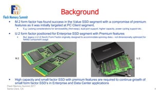


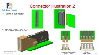
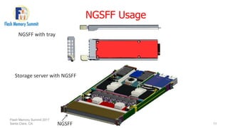


The document presents Samsung's proposal for the next generation small form factor (ngsff) SSD, aimed at improving upon existing m.2 and u.2 form factors by enhancing capacity, serviceability, and performance. The ngsff format is optimized for 1u servers and incorporates features like dual-port options and hot-swap capability while maintaining backward compatibility with m.2. Overall, the ngsff aims to significantly increase storage capacity and reliability for enterprise systems.


![5G Explained! A High Level Overview [Introduction]](https://cdn.slidesharecdn.com/ss_thumbnails/5gexplainedahighleveloverview-260119165306-cc137a3e-thumbnail.jpg?width=640&height=640&fit=bounds)


