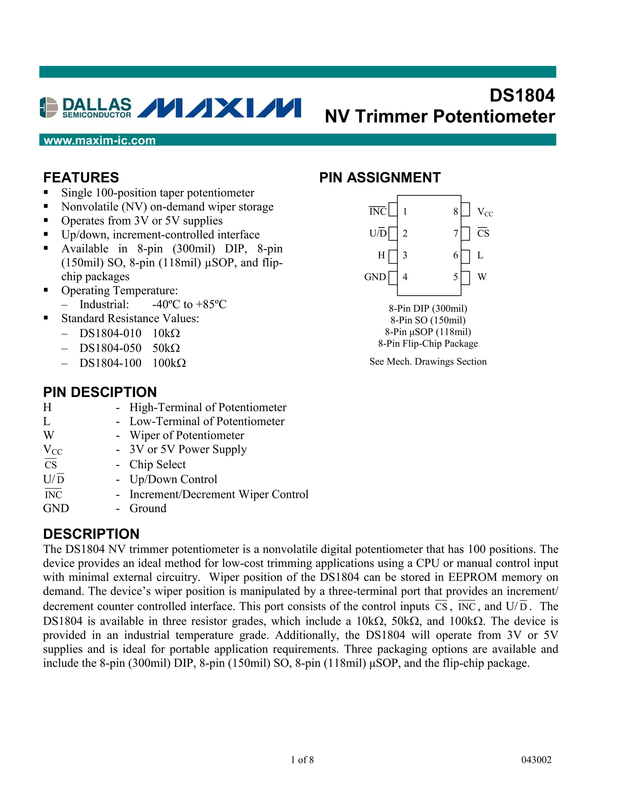
SlideShare a Scribd company logo
DS1804
                                                           NV Trimmer Potentiometer
www.maxim-ic.com


FEATURES                                                   PIN ASSIGNMENT
§   Single 100-position taper potentiometer
§   Nonvolatile (NV) on-demand wiper storage                       INC    1          8    VCC
§   Operates from 3V or 5V supplies
§   Up/down, increment-controlled interface                        U/D    2          7    CS
§   Available in 8-pin (300mil) DIP, 8-pin                          H     3          6    L
    (150mil) SO, 8-pin (118mil) µSOP, and flip-
    chip packages                                                 GND     4          5    W
§   Operating Temperature:
    – Industrial:     -40ºC to +85ºC                                   8-Pin DIP (300mil)
§   Standard Resistance Values:                                        8-Pin SO (150mil)
    – DS1804-010 10kW                                                 8-Pin µSOP (118mil)
                                                                    8-Pin Flip-Chip Package
    – DS1804-050 50kW
    – DS1804-100 100kW                                             See Mech. Drawings Section


PIN DESCIPTION
H             -   High-Terminal of Potentiometer
L             -   Low-Terminal of Potentiometer
W             -   Wiper of Potentiometer
VCC           -   3V or 5V Power Supply
CS            -   Chip Select
U/ D          -   Up/Down Control
INC           -   Increment/Decrement Wiper Control
GND           -   Ground

DESCRIPTION
The DS1804 NV trimmer potentiometer is a nonvolatile digital potentiometer that has 100 positions. The
device provides an ideal method for low-cost trimming applications using a CPU or manual control input
with minimal external circuitry. Wiper position of the DS1804 can be stored in EEPROM memory on
demand. The device’s wiper position is manipulated by a three-terminal port that provides an increment/
decrement counter controlled interface. This port consists of the control inputs CS , INC , and U/ D . The
DS1804 is available in three resistor grades, which include a 10kW, 50kW, and 100kW. The device is
provided in an industrial temperature grade. Additionally, the DS1804 will operate from 3V or 5V
supplies and is ideal for portable application requirements. Three packaging options are available and
include the 8-pin (300mil) DIP, 8-pin (150mil) SO, 8-pin (118mil) µSOP, and the flip-chip package.


                                                  1 of 8                                          043002
DS1804
OPERATION
The DS1804 is a single nonvolatile potentiometer. The device has a total of 100 tap-points including the
L- and H- terminals. A total of 99 resistive segments exist between the L- and H- terminals. These tap-
points are accessible to the W-terminal, whose position is controlled via a three-terminal control port. A
block diagram of the DS1804 is shown in Figure 1.

The three-terminal port of the DS1804 provides an increment/decrement interface which is activated via a
chip-select input. This interface consists of the input signals CS , INC , and U/ D . These input signals
control a 7-bit up/down counter. The output of the 7-bit up/down counter controls a 1 of 100 decoder to
select wiper position. Additionally, this interface provides for a wiper storage operation using the CS and
INC input control pins. The timing diagram for the three-terminal interface control is shown in Figure 2.

PIN DESCRIPTIONS
VCC - Power Supply. The DS1804 will support supply voltages ranging from +2.7V to +5.5V.

GND - Ground.

H - High-Terminal Potentiometer. This is the high terminal of the potentiometer. It is not required that
this terminal be connected to a potential greater than the L-terminal. Voltage applied to the H-terminal
cannot exceed the power-supply voltage, VCC, or go below ground.
L - Low-Terminal Potentiometer. This is the low terminal of the potentiometer. It is not required that this
terminal be connected to a potential less than the H-terminal. Voltage applied to the L-terminal cannot
exceed the power-supply voltage, VCC, or go below ground.

W - Wiper of the Potentiometer. This pin is the wiper of the potentiometer. Its position on the resistor
array is controlled by the three-terminal control port. Voltage applied to the wiper cannot exceed the
power-supply voltage, VCC, or go below ground.

CS  - Chip Select. The CS input is used to activate the control port of the DS1804. This input is active
low. When in a high-state, activity on the INC and U/ D port pins will not affect or change wiper
position.

INC  - Wiper Movement Control. This input provides for wiper position changes when the CS pin is low.
Wiper position changes of the W-terminal will occur one position per high-to-low transition of this input
signal. Position changes will not occur if the CS pin is in a high state.

U/ D - Up/Down Control. This input sets the direction of wiper movement. When in a high state and CS
is low, any high-to-low transition on INC will cause a one position movement of the wiper towards the
H-terminal. When in a low state and CS is low, any high-to-low transitions on INC will cause the
position of the wiper to move towards the L-terminal.


                                                   2 of 8
DS1804
DS1804 BLOCK DIAGRAM Figure 1


POWER-UP/POWER-DOWN CONDITIONS
On power-up, the DS1804 will load the value of EEPROM memory into the wiper position register (or 1
of 100 decoder). The value of this register can then be set to another wiper position if desired, by using
the three-terminal control port. On power-up, wiper position will be loaded within a maximum time
period of 500ms once the power-supply is stable. Additionally, the three-terminal interface port will be
active after 50ms.

On power-down, the wiper position register data will be lost. On the next device power-up, the value of
EEPROM memory will be loaded into the wiper position register.

On shipment from the factory, Dallas Semiconductor does not guarantee a specified EEPROM memory
value. This value should be set by the customer as needed.

NONVOLATILE WIPER STORAGE
Wiper position of the DS1804 can be stored using the INC and CS inputs. Storage of the wiper position
takes place whenever the CS input transitions from low-to-high while the INC is high. Once this
condition has occurred the value of the current wiper position will be written to EEPROM memory.

The DS1804 is specified to accept 50,000 writes to EEPROM before a wear-out condition. After wear-out
the DS1804 will still function and wiper position can be changed during powered conditions using the
three-terminal control port. However, on power-up the wiper-position will be indeterminate.

ONE-TIME PROGRAMMABILITY (OTP)
The DS1804 can be easily used as an OTP device. The user of the DS1804 can trim the desired value of
the wiper position and set this position for storage as described above. Any activity through the three-
terminal port can then be prevented by connecting the CS input pin to VCC. Also, an OTP application
does not adversely affect the number of times EEPROM is written, since EEPROM will only be loaded
and not written during a power-up or power-down condition.

On power-up, the DS1804 will load the current value of EEPROM memory into the wiper position
register.


                                                  3 of 8
DS1804
ABSOLUTE MAXIMUM RATINGS*
Voltage on Any Pin Relative to Ground                -1.0V to +7.0V
Operating Temperature Range                          -40°C to +85°C
Storage Temperature Range                            -55°C to +125°C
Soldering Temperature                                See IPC/JEDEC J-STD-020A Specification

* This is a stress rating only and functional operation of the device at these or any other conditions above
  those indicated in the operation sections of this specification is not implied. Exposure to absolute
  maximum rating conditions for extended periods of time may affect reliability.

1) Insert A (Burn-in Disclaimer)

The Dallas Semiconductor DS1804 is built to the highest quality standards and manufactured for long
term reliability. All Dallas Semiconductor devices are made using the same quality materials and
manufacturing methods. However, the flip-chip package version of the DS1804 is not exposed to
environmental stresses, such as burn-in, that some industrial applications require. For specific reliability
information on this product, please contact the factory in Dallas at 972-371-4448.

RECOMMENDED DC OPERATING CONDITIONS                                                  (-40°C to +85°C)
        PARAMETER                  SYMBOL          MIN         TYP         MAX        UNITS      NOTES
 Supply Voltage                      VCC           +2.7                     5.5          V          1
 Input Logic 1                        VIH           2.0                  VCC + 0.5       V          1,2

 Input Logic 0                        VIL          -0.5                    +0.8          V         1,15
                                                                           +0.6
 Resistor Inputs                    L,H,W       GND - 0.5                VCC + 0.5       V          1,3

DC ELECTRICAL CHARACTERISTICS                               (-40°C to +85°C; VCC= 2.7V to 5.5V)
         PARAMETER                  SYMBOL          MIN        TYP         MAX        UNITS      NOTES
 Supply Current                         ICC                                 400         µA          4
 Input Leakage                           ILI          -1                    +1          µA
 Wiper Resistance                       RW                      400        1000          W

 Wiper Current                           IW                                  1          mA
 Standby Current:
                                                                10                      µA
       3 Volts                         ISTBY                                40                      5
                                                                20                      µA
       5 Volts
 Wiper Load Time                        tWLT                    500                     µs          6
 Power-Up Time                          tPU                     50                      ms          14


                                                   4 of 8
DS1804
ANALOG RESISTOR CHARACTERISTICS (-40°C to +85°C; VCC= 2.7V to 5.5V)
         PARAMETER               SYMBOL      MIN       TYP      MAX     UNITS    NOTES
End-to-End Resistor Tolerance                -20                 +20       %        8
Absolute Linearity                                     ±0.6               LSB       9
Relative Linearity                                     ±0.25              LSB      10
-3dB Cutoff Frequency              fcutoff                               MHz       11
Temperature Coefficient                                750              ppm/°C

CAPACITANCE                                                    (25°C; VCC= 2.7V to 5.5V)
        PARAMETER               SYMBOL       MIN        TYP     MAX     UNITS    NOTES
Input Capacitance                 CIN                             5       pF       12
Output Capacitance               COUT                             7       pF       12

AC ELECTRICAL CHARACTERISTICS                         (-40°C to +85°C; VCC= 2.7V to 5.5V)
        PARAMETER               SYMBOL       MIN        TYP     MAX     UNITS    NOTES
CS to INC   Setup                 tCI         50                           ns      13

U/ D to INC Setup                 tDI        100                           ns      13
INC   Low Period                  tIL         50                           ns      13

INC   High Period                 tIH        100                           ns      13
INC   inactive to CS Inactive     tIC        500                           ns      13
CS   Deselect Time               tCPH        100                           ns      13
Wiper Change to INC Low           tIW                            200       ns      13

INC   Rise and Fall Times        tR , tF                         500      µs       13
INC   Low to CS Inactive          tIK         50                           ns      16
Wiper Storage Time               tWST                             10      ms      13, 17


                                             5 of 8
DS1804
NOTES:
1) All voltages are referenced to ground.
2) Valid for VCC = 5V only.
3) Resistor input voltages cannot go below ground or exceed VCC by the amounts as shown in the table.

4) Maximum current specifications are based on the clock rate of INC input. This specification
   represents the current required when changing the wiper position.

5) Standby current levels apply when all inputs are driven to appropriate supply levels. CS , INC , U/ D =
   VCC.
6) Wiper load time is specified as the time required for the DS1804 to load the wiper position with the
   contents of nonvolatile memory once VCC has reached a stable operating voltage equal to or greater
   than 2.7V.
7) The DS1804 is available in three resistor values. These include the DS1804-010, 10kW; the DS1804-
   050, 50kW; and the DS1804-100, 100kW.
8) Valid at 25°C only.

9) Absolute linearity is used to compare measured wiper voltage versus expected wiper voltage as
   determined by wiper position. The DS1804 is specified to provide an absolute linearity of ±0.60 LSB.
10) Relative linearity is used to determined the change in voltage between successive tap positions. The
    DS1804 is specified to provide a relative linearity specification of ±0.25 LSB.
11) -3dB cutoff frequency characteristics for the DS1804 depend on potentiometer total resistance.
    DS1804-010, 1MHz; DS1804-050, 200 kHz; and DS1804-100, 100 kHz.
12) Capacitance values apply at 25°C.
13) See Figure 2.
14) Power-up time is specified as the time required before the three-terminal control becomes active after
    a stable power supply level has been reached.
15) At VCC = 2.7V, VIL = 0.8V.

16) The INC low to CS inactive is specified to be 50ns minimum. This is the transition condition which
    allows the DS1804 three-terminal port to become inactive without writing the EEPROM memory of
    the part.
17) Wiper Storage Time, tWST, is the time require for the DS1804 to write EEPROM memory for storage
    of a new wiper position. The maximum time required to accomplish this task is specified at 10ms.


                                                  6 of 8
DS1804
THREE-TERMINAL INTERFACE TIMING DIAGRAM Figure 2


DS1804 ORDERING INFORMATION
   ORDERING                                   OPERATING
                    PACKAGE                                   VERSION
    NUMBER                                   TEMPERATURE
DS1804-010        8L DIP (300MIL)            -40°C TO +85°C    10kW
DS1804-050        8L DIP (300MIL)            -40°C TO +85°C    50kW
DS1804-100        8L DIP (300MIL)            -40°C TO +85°C    100kW
DS1804Z-010      8L SOIC (150MIL)            -40°C TO +85°C    10kW
DS1804Z-050      8L SOIC (150MIL)            -40°C TO +85°C    50kW
DS1804Z-100      8L SOIC (150MIL)            -40°C TO +85°C    100kW
DS1804U-010      8L µSOP (118MIL)            -40°C TO +85°C    10kW
DS1804U-050      8L µSOP (118MIL)            -40°C TO +85°C    50kW
DS1804U-100      8L µSOP (118MIL)            -40°C TO +85°C    100kW
DS1804X-010       8L FCP (118MIL)            -40°C TO +85°C    10kW
DS1804X-050       8L FCP (118MIL)            -40°C TO +85°C    50kW
DS1804X-100       8L FCP (118MIL)            -40°C TO +85°C    100kW


                                    7 of 8
DS1804
BRANDING INFORMATION Figure 3
                               Top Brand                           Bottom Brand


                              DS1804-nnn
           8-pin
                                yywwrv                                  cccccc
            DIP
                                 ###xx


                                  DS1804m
           8-pin
                                   yywwrv                                 cccccc
           SOIC
                                    ###xx


       8-pin                           1804                                  yyww
       uSOP                            rvnnn                                 ###xx


                                        DS1804 Brand Codes
       Code                   Description              Values
                                                       010       10k ohm
      nnn          Pot Size (DIP/uSOP)                 050       50k ohm
                                                       100       100k ohm
      m            Pot Size (SOIC)                     X         10k ohm
                                                       L         50k ohm
                                                       C         100k ohm

      yyww         Date Code. It identifies the year   eg. 0035 is the 35th work week
                   and work week the device was        of 2000
                   assembled

      rv           Die Revision                        Generally this is a letter followed
                                                       by a number (eg. B2)

      ###xx        Lot Code

      cccccc       Country of Assembly


                                                        8 of 8

More Related Content

What's hot

Acs712 datasheet
Acs712 datasheetAcs712 datasheet
Acs712 datasheet
Felipe Mejia
 
Acs712
Acs712Acs712
Acs712
fbwicky87
 
TV Remote Operated Domestic Appliances Control
TV Remote Operated Domestic Appliances ControlTV Remote Operated Domestic Appliances Control
TV Remote Operated Domestic Appliances Control
Edgefxkits & Solutions
 
CONTROLLING HOME APPLIANCES USING REMOTE(1)
CONTROLLING HOME APPLIANCES USING REMOTE(1)CONTROLLING HOME APPLIANCES USING REMOTE(1)
CONTROLLING HOME APPLIANCES USING REMOTE(1)
Ambar Gupta
 
Smart Implant- Fibaro- Z-Wave
Smart Implant- Fibaro- Z-WaveSmart Implant- Fibaro- Z-Wave
Smart Implant- Fibaro- Z-Wave
Domotica daVinci
 
Netzer ds 37-16-specsheet
Netzer ds 37-16-specsheetNetzer ds 37-16-specsheet
Netzer ds 37-16-specsheet
Electromate
 
Uno 2.0-2.5
Uno 2.0-2.5Uno 2.0-2.5
Edwards Signaling E-NAC Installation Manual
Edwards Signaling E-NAC Installation ManualEdwards Signaling E-NAC Installation Manual
Edwards Signaling E-NAC Installation Manual
JMAC Supply
 
Remote controlling of home appliance by moniruzzaman iiuc
Remote controlling of home appliance by moniruzzaman iiuc Remote controlling of home appliance by moniruzzaman iiuc
Remote controlling of home appliance by moniruzzaman iiuc
Md Moneruzzman
 
MICROCONTROLLER BASED IR FOR HOME APPLICATION
MICROCONTROLLER BASED IR FOR HOME APPLICATIONMICROCONTROLLER BASED IR FOR HOME APPLICATION
MICROCONTROLLER BASED IR FOR HOME APPLICATION
Jahir Hussain
 
Electronic test equipment, Oscilloscope, Spectrum, Analyzer ,DMM
Electronic test equipment, Oscilloscope, Spectrum, Analyzer ,DMMElectronic test equipment, Oscilloscope, Spectrum, Analyzer ,DMM
Electronic test equipment, Oscilloscope, Spectrum, Analyzer ,DMM
Emily Tan
 
Advanced motion controls az60a8ddc
Advanced motion controls az60a8ddcAdvanced motion controls az60a8ddc
Advanced motion controls az60a8ddc
Electromate
 
Easy pacttvs catalogues lc1e
Easy pacttvs catalogues lc1eEasy pacttvs catalogues lc1e
Easy pacttvs catalogues lc1e
Hoàng Phương JSC
 
FMA246_datasheet
FMA246_datasheetFMA246_datasheet
FMA246_datasheet
RF LTE 5G WLAN PA Jeong Lee
 
AODesign&Protection_2015_noNDA
AODesign&Protection_2015_noNDAAODesign&Protection_2015_noNDA
AODesign&Protection_2015_noNDA
Kevin Duke
 
Wireless Gesture Controlled Tank Toy- Transmitter
Wireless Gesture Controlled Tank Toy- TransmitterWireless Gesture Controlled Tank Toy- Transmitter
Wireless Gesture Controlled Tank Toy- Transmitter
Neeraj Purohit
 
S123 b30u
S123 b30uS123 b30u
S123 b30u
Domotica daVinci
 
Controlling home appliances using remote (2)
Controlling home appliances using remote (2)Controlling home appliances using remote (2)
Controlling home appliances using remote (2)
K Vivek Varkey
 
Remote control for home appliances
Remote control for home appliancesRemote control for home appliances
Remote control for home appliances
Bharath University
 

What's hot (19)

Acs712 datasheet
Acs712 datasheetAcs712 datasheet
Acs712 datasheet
 
Acs712
Acs712Acs712
Acs712
 
TV Remote Operated Domestic Appliances Control
TV Remote Operated Domestic Appliances ControlTV Remote Operated Domestic Appliances Control
TV Remote Operated Domestic Appliances Control
 
CONTROLLING HOME APPLIANCES USING REMOTE(1)
CONTROLLING HOME APPLIANCES USING REMOTE(1)CONTROLLING HOME APPLIANCES USING REMOTE(1)
CONTROLLING HOME APPLIANCES USING REMOTE(1)
 
Smart Implant- Fibaro- Z-Wave
Smart Implant- Fibaro- Z-WaveSmart Implant- Fibaro- Z-Wave
Smart Implant- Fibaro- Z-Wave
 
Netzer ds 37-16-specsheet
Netzer ds 37-16-specsheetNetzer ds 37-16-specsheet
Netzer ds 37-16-specsheet
 
Uno 2.0-2.5
Uno 2.0-2.5Uno 2.0-2.5
Uno 2.0-2.5
 
Edwards Signaling E-NAC Installation Manual
Edwards Signaling E-NAC Installation ManualEdwards Signaling E-NAC Installation Manual
Edwards Signaling E-NAC Installation Manual
 
Remote controlling of home appliance by moniruzzaman iiuc
Remote controlling of home appliance by moniruzzaman iiuc Remote controlling of home appliance by moniruzzaman iiuc
Remote controlling of home appliance by moniruzzaman iiuc
 
MICROCONTROLLER BASED IR FOR HOME APPLICATION
MICROCONTROLLER BASED IR FOR HOME APPLICATIONMICROCONTROLLER BASED IR FOR HOME APPLICATION
MICROCONTROLLER BASED IR FOR HOME APPLICATION
 
Electronic test equipment, Oscilloscope, Spectrum, Analyzer ,DMM
Electronic test equipment, Oscilloscope, Spectrum, Analyzer ,DMMElectronic test equipment, Oscilloscope, Spectrum, Analyzer ,DMM
Electronic test equipment, Oscilloscope, Spectrum, Analyzer ,DMM
 
Advanced motion controls az60a8ddc
Advanced motion controls az60a8ddcAdvanced motion controls az60a8ddc
Advanced motion controls az60a8ddc
 
Easy pacttvs catalogues lc1e
Easy pacttvs catalogues lc1eEasy pacttvs catalogues lc1e
Easy pacttvs catalogues lc1e
 
FMA246_datasheet
FMA246_datasheetFMA246_datasheet
FMA246_datasheet
 
AODesign&Protection_2015_noNDA
AODesign&Protection_2015_noNDAAODesign&Protection_2015_noNDA
AODesign&Protection_2015_noNDA
 
Wireless Gesture Controlled Tank Toy- Transmitter
Wireless Gesture Controlled Tank Toy- TransmitterWireless Gesture Controlled Tank Toy- Transmitter
Wireless Gesture Controlled Tank Toy- Transmitter
 
S123 b30u
S123 b30uS123 b30u
S123 b30u
 
Controlling home appliances using remote (2)
Controlling home appliances using remote (2)Controlling home appliances using remote (2)
Controlling home appliances using remote (2)
 
Remote control for home appliances
Remote control for home appliancesRemote control for home appliances
Remote control for home appliances
 

Similar to Digital potentiometer ds1804 010+

Advanced motion controls avb200a100
Advanced motion controls avb200a100Advanced motion controls avb200a100
Advanced motion controls avb200a100
Electromate
 
Drv8833 motor driver datasheet
Drv8833 motor driver datasheetDrv8833 motor driver datasheet
Drv8833 motor driver datasheet
Mahmut Yildiz
 
lm3914.pdf
lm3914.pdflm3914.pdf
Advanced motion controls s30a40ac
Advanced motion controls s30a40acAdvanced motion controls s30a40ac
Advanced motion controls s30a40ac
Electromate
 
Advanced motion controls avb100c200
Advanced motion controls avb100c200Advanced motion controls avb100c200
Advanced motion controls avb100c200
Electromate
 
Advanced motion controls avb250a060
Advanced motion controls avb250a060Advanced motion controls avb250a060
Advanced motion controls avb250a060
Electromate
 
Advanced motion controls avb125a200
Advanced motion controls avb125a200Advanced motion controls avb125a200
Advanced motion controls avb125a200
Electromate
 
Advanced motion controls ab200a100
Advanced motion controls ab200a100Advanced motion controls ab200a100
Advanced motion controls ab200a100
Electromate
 
Advanced motion controls s100a40ac
Advanced motion controls s100a40acAdvanced motion controls s100a40ac
Advanced motion controls s100a40ac
Electromate
 
Advanced motion controls s60a40ac
Advanced motion controls s60a40acAdvanced motion controls s60a40ac
Advanced motion controls s60a40ac
Electromate
 
Advanced motion controls mc1xzdr
Advanced motion controls mc1xzdrAdvanced motion controls mc1xzdr
Advanced motion controls mc1xzdr
Electromate
 
Advanced motion controls s100a20
Advanced motion controls s100a20Advanced motion controls s100a20
Advanced motion controls s100a20
Electromate
 
Advanced motion controls b100a8
Advanced motion controls b100a8Advanced motion controls b100a8
Advanced motion controls b100a8
Electromate
 
Advanced motion controls b100a40ac
Advanced motion controls b100a40acAdvanced motion controls b100a40ac
Advanced motion controls b100a40ac
Electromate
 
Advanced motion controls b60a40ac
Advanced motion controls b60a40acAdvanced motion controls b60a40ac
Advanced motion controls b60a40ac
Electromate
 
Advanced motion controls ab100c200
Advanced motion controls ab100c200Advanced motion controls ab100c200
Advanced motion controls ab100c200
Electromate
 
Advanced motion controls s100a8
Advanced motion controls s100a8Advanced motion controls s100a8
Advanced motion controls s100a8
Electromate
 
Advanced motion controls b30a40ac
Advanced motion controls b30a40acAdvanced motion controls b30a40ac
Advanced motion controls b30a40ac
Electromate
 
Advanced motion controls 25a20
Advanced motion controls 25a20Advanced motion controls 25a20
Advanced motion controls 25a20
Electromate
 
Advanced motion controls b100a40
Advanced motion controls b100a40Advanced motion controls b100a40
Advanced motion controls b100a40
Electromate
 

Similar to Digital potentiometer ds1804 010+ (20)

Advanced motion controls avb200a100
Advanced motion controls avb200a100Advanced motion controls avb200a100
Advanced motion controls avb200a100
 
Drv8833 motor driver datasheet
Drv8833 motor driver datasheetDrv8833 motor driver datasheet
Drv8833 motor driver datasheet
 
lm3914.pdf
lm3914.pdflm3914.pdf
lm3914.pdf
 
Advanced motion controls s30a40ac
Advanced motion controls s30a40acAdvanced motion controls s30a40ac
Advanced motion controls s30a40ac
 
Advanced motion controls avb100c200
Advanced motion controls avb100c200Advanced motion controls avb100c200
Advanced motion controls avb100c200
 
Advanced motion controls avb250a060
Advanced motion controls avb250a060Advanced motion controls avb250a060
Advanced motion controls avb250a060
 
Advanced motion controls avb125a200
Advanced motion controls avb125a200Advanced motion controls avb125a200
Advanced motion controls avb125a200
 
Advanced motion controls ab200a100
Advanced motion controls ab200a100Advanced motion controls ab200a100
Advanced motion controls ab200a100
 
Advanced motion controls s100a40ac
Advanced motion controls s100a40acAdvanced motion controls s100a40ac
Advanced motion controls s100a40ac
 
Advanced motion controls s60a40ac
Advanced motion controls s60a40acAdvanced motion controls s60a40ac
Advanced motion controls s60a40ac
 
Advanced motion controls mc1xzdr
Advanced motion controls mc1xzdrAdvanced motion controls mc1xzdr
Advanced motion controls mc1xzdr
 
Advanced motion controls s100a20
Advanced motion controls s100a20Advanced motion controls s100a20
Advanced motion controls s100a20
 
Advanced motion controls b100a8
Advanced motion controls b100a8Advanced motion controls b100a8
Advanced motion controls b100a8
 
Advanced motion controls b100a40ac
Advanced motion controls b100a40acAdvanced motion controls b100a40ac
Advanced motion controls b100a40ac
 
Advanced motion controls b60a40ac
Advanced motion controls b60a40acAdvanced motion controls b60a40ac
Advanced motion controls b60a40ac
 
Advanced motion controls ab100c200
Advanced motion controls ab100c200Advanced motion controls ab100c200
Advanced motion controls ab100c200
 
Advanced motion controls s100a8
Advanced motion controls s100a8Advanced motion controls s100a8
Advanced motion controls s100a8
 
Advanced motion controls b30a40ac
Advanced motion controls b30a40acAdvanced motion controls b30a40ac
Advanced motion controls b30a40ac
 
Advanced motion controls 25a20
Advanced motion controls 25a20Advanced motion controls 25a20
Advanced motion controls 25a20
 
Advanced motion controls b100a40
Advanced motion controls b100a40Advanced motion controls b100a40
Advanced motion controls b100a40
 

Recently uploaded

Cosa hanno in comune un mattoncino Lego e la backdoor XZ?
Cosa hanno in comune un mattoncino Lego e la backdoor XZ?Cosa hanno in comune un mattoncino Lego e la backdoor XZ?
Cosa hanno in comune un mattoncino Lego e la backdoor XZ?
Speck&Tech
 
Why You Should Replace Windows 11 with Nitrux Linux 3.5.0 for enhanced perfor...
Why You Should Replace Windows 11 with Nitrux Linux 3.5.0 for enhanced perfor...Why You Should Replace Windows 11 with Nitrux Linux 3.5.0 for enhanced perfor...
Why You Should Replace Windows 11 with Nitrux Linux 3.5.0 for enhanced perfor...
SOFTTECHHUB
 
“I’m still / I’m still / Chaining from the Block”
“I’m still / I’m still / Chaining from the Block”“I’m still / I’m still / Chaining from the Block”
“I’m still / I’m still / Chaining from the Block”
Claudio Di Ciccio
 
RESUME BUILDER APPLICATION Project for students
RESUME BUILDER APPLICATION Project for studentsRESUME BUILDER APPLICATION Project for students
RESUME BUILDER APPLICATION Project for students
KAMESHS29
 
GraphSummit Singapore | The Art of the Possible with Graph - Q2 2024
GraphSummit Singapore | The Art of the  Possible with Graph - Q2 2024GraphSummit Singapore | The Art of the  Possible with Graph - Q2 2024
GraphSummit Singapore | The Art of the Possible with Graph - Q2 2024
Neo4j
 
Monitoring Java Application Security with JDK Tools and JFR Events
Monitoring Java Application Security with JDK Tools and JFR EventsMonitoring Java Application Security with JDK Tools and JFR Events
Monitoring Java Application Security with JDK Tools and JFR Events
Ana-Maria Mihalceanu
 
Video Streaming: Then, Now, and in the Future
Video Streaming: Then, Now, and in the FutureVideo Streaming: Then, Now, and in the Future
Video Streaming: Then, Now, and in the Future
Alpen-Adria-Universität
 
Securing your Kubernetes cluster_ a step-by-step guide to success !
Securing your Kubernetes cluster_ a step-by-step guide to success !Securing your Kubernetes cluster_ a step-by-step guide to success !
Securing your Kubernetes cluster_ a step-by-step guide to success !
KatiaHIMEUR1
 
Alt. GDG Cloud Southlake #33: Boule & Rebala: Effective AppSec in SDLC using ...
Alt. GDG Cloud Southlake #33: Boule & Rebala: Effective AppSec in SDLC using ...Alt. GDG Cloud Southlake #33: Boule & Rebala: Effective AppSec in SDLC using ...
Alt. GDG Cloud Southlake #33: Boule & Rebala: Effective AppSec in SDLC using ...
James Anderson
 
Communications Mining Series - Zero to Hero - Session 1
Communications Mining Series - Zero to Hero - Session 1Communications Mining Series - Zero to Hero - Session 1
Communications Mining Series - Zero to Hero - Session 1
DianaGray10
 
How to use Firebase Data Connect For Flutter
How to use Firebase Data Connect For FlutterHow to use Firebase Data Connect For Flutter
How to use Firebase Data Connect For Flutter
Daiki Mogmet Ito
 
TrustArc Webinar - 2024 Global Privacy Survey
TrustArc Webinar - 2024 Global Privacy SurveyTrustArc Webinar - 2024 Global Privacy Survey
TrustArc Webinar - 2024 Global Privacy Survey
TrustArc
 
Removing Uninteresting Bytes in Software Fuzzing
Removing Uninteresting Bytes in Software FuzzingRemoving Uninteresting Bytes in Software Fuzzing
Removing Uninteresting Bytes in Software Fuzzing
Aftab Hussain
 
Introduction to CHERI technology - Cybersecurity
Introduction to CHERI technology - CybersecurityIntroduction to CHERI technology - Cybersecurity
Introduction to CHERI technology - Cybersecurity
mikeeftimakis1
 
UiPath Test Automation using UiPath Test Suite series, part 6
UiPath Test Automation using UiPath Test Suite series, part 6UiPath Test Automation using UiPath Test Suite series, part 6
UiPath Test Automation using UiPath Test Suite series, part 6
DianaGray10
 
National Security Agency - NSA mobile device best practices
National Security Agency - NSA mobile device best practicesNational Security Agency - NSA mobile device best practices
National Security Agency - NSA mobile device best practices
Quotidiano Piemontese
 
Unlock the Future of Search with MongoDB Atlas_ Vector Search Unleashed.pdf
Unlock the Future of Search with MongoDB Atlas_ Vector Search Unleashed.pdfUnlock the Future of Search with MongoDB Atlas_ Vector Search Unleashed.pdf
Unlock the Future of Search with MongoDB Atlas_ Vector Search Unleashed.pdf
Malak Abu Hammad
 
PCI PIN Basics Webinar from the Controlcase Team
PCI PIN Basics Webinar from the Controlcase TeamPCI PIN Basics Webinar from the Controlcase Team
PCI PIN Basics Webinar from the Controlcase Team
ControlCase
 
Essentials of Automations: The Art of Triggers and Actions in FME
Essentials of Automations: The Art of Triggers and Actions in FMEEssentials of Automations: The Art of Triggers and Actions in FME
Essentials of Automations: The Art of Triggers and Actions in FME
Safe Software
 
Introducing Milvus Lite: Easy-to-Install, Easy-to-Use vector database for you...
Introducing Milvus Lite: Easy-to-Install, Easy-to-Use vector database for you...Introducing Milvus Lite: Easy-to-Install, Easy-to-Use vector database for you...
Introducing Milvus Lite: Easy-to-Install, Easy-to-Use vector database for you...
Zilliz
 

Recently uploaded (20)

Cosa hanno in comune un mattoncino Lego e la backdoor XZ?
Cosa hanno in comune un mattoncino Lego e la backdoor XZ?Cosa hanno in comune un mattoncino Lego e la backdoor XZ?
Cosa hanno in comune un mattoncino Lego e la backdoor XZ?
 
Why You Should Replace Windows 11 with Nitrux Linux 3.5.0 for enhanced perfor...
Why You Should Replace Windows 11 with Nitrux Linux 3.5.0 for enhanced perfor...Why You Should Replace Windows 11 with Nitrux Linux 3.5.0 for enhanced perfor...
Why You Should Replace Windows 11 with Nitrux Linux 3.5.0 for enhanced perfor...
 
“I’m still / I’m still / Chaining from the Block”
“I’m still / I’m still / Chaining from the Block”“I’m still / I’m still / Chaining from the Block”
“I’m still / I’m still / Chaining from the Block”
 
RESUME BUILDER APPLICATION Project for students
RESUME BUILDER APPLICATION Project for studentsRESUME BUILDER APPLICATION Project for students
RESUME BUILDER APPLICATION Project for students
 
GraphSummit Singapore | The Art of the Possible with Graph - Q2 2024
GraphSummit Singapore | The Art of the  Possible with Graph - Q2 2024GraphSummit Singapore | The Art of the  Possible with Graph - Q2 2024
GraphSummit Singapore | The Art of the Possible with Graph - Q2 2024
 
Monitoring Java Application Security with JDK Tools and JFR Events
Monitoring Java Application Security with JDK Tools and JFR EventsMonitoring Java Application Security with JDK Tools and JFR Events
Monitoring Java Application Security with JDK Tools and JFR Events
 
Video Streaming: Then, Now, and in the Future
Video Streaming: Then, Now, and in the FutureVideo Streaming: Then, Now, and in the Future
Video Streaming: Then, Now, and in the Future
 
Securing your Kubernetes cluster_ a step-by-step guide to success !
Securing your Kubernetes cluster_ a step-by-step guide to success !Securing your Kubernetes cluster_ a step-by-step guide to success !
Securing your Kubernetes cluster_ a step-by-step guide to success !
 
Alt. GDG Cloud Southlake #33: Boule & Rebala: Effective AppSec in SDLC using ...
Alt. GDG Cloud Southlake #33: Boule & Rebala: Effective AppSec in SDLC using ...Alt. GDG Cloud Southlake #33: Boule & Rebala: Effective AppSec in SDLC using ...
Alt. GDG Cloud Southlake #33: Boule & Rebala: Effective AppSec in SDLC using ...
 
Communications Mining Series - Zero to Hero - Session 1
Communications Mining Series - Zero to Hero - Session 1Communications Mining Series - Zero to Hero - Session 1
Communications Mining Series - Zero to Hero - Session 1
 
How to use Firebase Data Connect For Flutter
How to use Firebase Data Connect For FlutterHow to use Firebase Data Connect For Flutter
How to use Firebase Data Connect For Flutter
 
TrustArc Webinar - 2024 Global Privacy Survey
TrustArc Webinar - 2024 Global Privacy SurveyTrustArc Webinar - 2024 Global Privacy Survey
TrustArc Webinar - 2024 Global Privacy Survey
 
Removing Uninteresting Bytes in Software Fuzzing
Removing Uninteresting Bytes in Software FuzzingRemoving Uninteresting Bytes in Software Fuzzing
Removing Uninteresting Bytes in Software Fuzzing
 
Introduction to CHERI technology - Cybersecurity
Introduction to CHERI technology - CybersecurityIntroduction to CHERI technology - Cybersecurity
Introduction to CHERI technology - Cybersecurity
 
UiPath Test Automation using UiPath Test Suite series, part 6
UiPath Test Automation using UiPath Test Suite series, part 6UiPath Test Automation using UiPath Test Suite series, part 6
UiPath Test Automation using UiPath Test Suite series, part 6
 
National Security Agency - NSA mobile device best practices
National Security Agency - NSA mobile device best practicesNational Security Agency - NSA mobile device best practices
National Security Agency - NSA mobile device best practices
 
Unlock the Future of Search with MongoDB Atlas_ Vector Search Unleashed.pdf
Unlock the Future of Search with MongoDB Atlas_ Vector Search Unleashed.pdfUnlock the Future of Search with MongoDB Atlas_ Vector Search Unleashed.pdf
Unlock the Future of Search with MongoDB Atlas_ Vector Search Unleashed.pdf
 
PCI PIN Basics Webinar from the Controlcase Team
PCI PIN Basics Webinar from the Controlcase TeamPCI PIN Basics Webinar from the Controlcase Team
PCI PIN Basics Webinar from the Controlcase Team
 
Essentials of Automations: The Art of Triggers and Actions in FME
Essentials of Automations: The Art of Triggers and Actions in FMEEssentials of Automations: The Art of Triggers and Actions in FME
Essentials of Automations: The Art of Triggers and Actions in FME
 
Introducing Milvus Lite: Easy-to-Install, Easy-to-Use vector database for you...
Introducing Milvus Lite: Easy-to-Install, Easy-to-Use vector database for you...Introducing Milvus Lite: Easy-to-Install, Easy-to-Use vector database for you...
Introducing Milvus Lite: Easy-to-Install, Easy-to-Use vector database for you...
 

Digital potentiometer ds1804 010+

  • 1. DS1804 NV Trimmer Potentiometer www.maxim-ic.com FEATURES PIN ASSIGNMENT § Single 100-position taper potentiometer § Nonvolatile (NV) on-demand wiper storage INC 1 8 VCC § Operates from 3V or 5V supplies § Up/down, increment-controlled interface U/D 2 7 CS § Available in 8-pin (300mil) DIP, 8-pin H 3 6 L (150mil) SO, 8-pin (118mil) µSOP, and flip- chip packages GND 4 5 W § Operating Temperature: – Industrial: -40ºC to +85ºC 8-Pin DIP (300mil) § Standard Resistance Values: 8-Pin SO (150mil) – DS1804-010 10kW 8-Pin µSOP (118mil) 8-Pin Flip-Chip Package – DS1804-050 50kW – DS1804-100 100kW See Mech. Drawings Section PIN DESCIPTION H - High-Terminal of Potentiometer L - Low-Terminal of Potentiometer W - Wiper of Potentiometer VCC - 3V or 5V Power Supply CS - Chip Select U/ D - Up/Down Control INC - Increment/Decrement Wiper Control GND - Ground DESCRIPTION The DS1804 NV trimmer potentiometer is a nonvolatile digital potentiometer that has 100 positions. The device provides an ideal method for low-cost trimming applications using a CPU or manual control input with minimal external circuitry. Wiper position of the DS1804 can be stored in EEPROM memory on demand. The device’s wiper position is manipulated by a three-terminal port that provides an increment/ decrement counter controlled interface. This port consists of the control inputs CS , INC , and U/ D . The DS1804 is available in three resistor grades, which include a 10kW, 50kW, and 100kW. The device is provided in an industrial temperature grade. Additionally, the DS1804 will operate from 3V or 5V supplies and is ideal for portable application requirements. Three packaging options are available and include the 8-pin (300mil) DIP, 8-pin (150mil) SO, 8-pin (118mil) µSOP, and the flip-chip package. 1 of 8 043002
  • 2. DS1804 OPERATION The DS1804 is a single nonvolatile potentiometer. The device has a total of 100 tap-points including the L- and H- terminals. A total of 99 resistive segments exist between the L- and H- terminals. These tap- points are accessible to the W-terminal, whose position is controlled via a three-terminal control port. A block diagram of the DS1804 is shown in Figure 1. The three-terminal port of the DS1804 provides an increment/decrement interface which is activated via a chip-select input. This interface consists of the input signals CS , INC , and U/ D . These input signals control a 7-bit up/down counter. The output of the 7-bit up/down counter controls a 1 of 100 decoder to select wiper position. Additionally, this interface provides for a wiper storage operation using the CS and INC input control pins. The timing diagram for the three-terminal interface control is shown in Figure 2. PIN DESCRIPTIONS VCC - Power Supply. The DS1804 will support supply voltages ranging from +2.7V to +5.5V. GND - Ground. H - High-Terminal Potentiometer. This is the high terminal of the potentiometer. It is not required that this terminal be connected to a potential greater than the L-terminal. Voltage applied to the H-terminal cannot exceed the power-supply voltage, VCC, or go below ground. L - Low-Terminal Potentiometer. This is the low terminal of the potentiometer. It is not required that this terminal be connected to a potential less than the H-terminal. Voltage applied to the L-terminal cannot exceed the power-supply voltage, VCC, or go below ground. W - Wiper of the Potentiometer. This pin is the wiper of the potentiometer. Its position on the resistor array is controlled by the three-terminal control port. Voltage applied to the wiper cannot exceed the power-supply voltage, VCC, or go below ground. CS - Chip Select. The CS input is used to activate the control port of the DS1804. This input is active low. When in a high-state, activity on the INC and U/ D port pins will not affect or change wiper position. INC - Wiper Movement Control. This input provides for wiper position changes when the CS pin is low. Wiper position changes of the W-terminal will occur one position per high-to-low transition of this input signal. Position changes will not occur if the CS pin is in a high state. U/ D - Up/Down Control. This input sets the direction of wiper movement. When in a high state and CS is low, any high-to-low transition on INC will cause a one position movement of the wiper towards the H-terminal. When in a low state and CS is low, any high-to-low transitions on INC will cause the position of the wiper to move towards the L-terminal. 2 of 8
  • 3. DS1804 DS1804 BLOCK DIAGRAM Figure 1 POWER-UP/POWER-DOWN CONDITIONS On power-up, the DS1804 will load the value of EEPROM memory into the wiper position register (or 1 of 100 decoder). The value of this register can then be set to another wiper position if desired, by using the three-terminal control port. On power-up, wiper position will be loaded within a maximum time period of 500ms once the power-supply is stable. Additionally, the three-terminal interface port will be active after 50ms. On power-down, the wiper position register data will be lost. On the next device power-up, the value of EEPROM memory will be loaded into the wiper position register. On shipment from the factory, Dallas Semiconductor does not guarantee a specified EEPROM memory value. This value should be set by the customer as needed. NONVOLATILE WIPER STORAGE Wiper position of the DS1804 can be stored using the INC and CS inputs. Storage of the wiper position takes place whenever the CS input transitions from low-to-high while the INC is high. Once this condition has occurred the value of the current wiper position will be written to EEPROM memory. The DS1804 is specified to accept 50,000 writes to EEPROM before a wear-out condition. After wear-out the DS1804 will still function and wiper position can be changed during powered conditions using the three-terminal control port. However, on power-up the wiper-position will be indeterminate. ONE-TIME PROGRAMMABILITY (OTP) The DS1804 can be easily used as an OTP device. The user of the DS1804 can trim the desired value of the wiper position and set this position for storage as described above. Any activity through the three- terminal port can then be prevented by connecting the CS input pin to VCC. Also, an OTP application does not adversely affect the number of times EEPROM is written, since EEPROM will only be loaded and not written during a power-up or power-down condition. On power-up, the DS1804 will load the current value of EEPROM memory into the wiper position register. 3 of 8
  • 4. DS1804 ABSOLUTE MAXIMUM RATINGS* Voltage on Any Pin Relative to Ground -1.0V to +7.0V Operating Temperature Range -40°C to +85°C Storage Temperature Range -55°C to +125°C Soldering Temperature See IPC/JEDEC J-STD-020A Specification * This is a stress rating only and functional operation of the device at these or any other conditions above those indicated in the operation sections of this specification is not implied. Exposure to absolute maximum rating conditions for extended periods of time may affect reliability. 1) Insert A (Burn-in Disclaimer) The Dallas Semiconductor DS1804 is built to the highest quality standards and manufactured for long term reliability. All Dallas Semiconductor devices are made using the same quality materials and manufacturing methods. However, the flip-chip package version of the DS1804 is not exposed to environmental stresses, such as burn-in, that some industrial applications require. For specific reliability information on this product, please contact the factory in Dallas at 972-371-4448. RECOMMENDED DC OPERATING CONDITIONS (-40°C to +85°C) PARAMETER SYMBOL MIN TYP MAX UNITS NOTES Supply Voltage VCC +2.7 5.5 V 1 Input Logic 1 VIH 2.0 VCC + 0.5 V 1,2 Input Logic 0 VIL -0.5 +0.8 V 1,15 +0.6 Resistor Inputs L,H,W GND - 0.5 VCC + 0.5 V 1,3 DC ELECTRICAL CHARACTERISTICS (-40°C to +85°C; VCC= 2.7V to 5.5V) PARAMETER SYMBOL MIN TYP MAX UNITS NOTES Supply Current ICC 400 µA 4 Input Leakage ILI -1 +1 µA Wiper Resistance RW 400 1000 W Wiper Current IW 1 mA Standby Current: 10 µA 3 Volts ISTBY 40 5 20 µA 5 Volts Wiper Load Time tWLT 500 µs 6 Power-Up Time tPU 50 ms 14 4 of 8
  • 5. DS1804 ANALOG RESISTOR CHARACTERISTICS (-40°C to +85°C; VCC= 2.7V to 5.5V) PARAMETER SYMBOL MIN TYP MAX UNITS NOTES End-to-End Resistor Tolerance -20 +20 % 8 Absolute Linearity ±0.6 LSB 9 Relative Linearity ±0.25 LSB 10 -3dB Cutoff Frequency fcutoff MHz 11 Temperature Coefficient 750 ppm/°C CAPACITANCE (25°C; VCC= 2.7V to 5.5V) PARAMETER SYMBOL MIN TYP MAX UNITS NOTES Input Capacitance CIN 5 pF 12 Output Capacitance COUT 7 pF 12 AC ELECTRICAL CHARACTERISTICS (-40°C to +85°C; VCC= 2.7V to 5.5V) PARAMETER SYMBOL MIN TYP MAX UNITS NOTES CS to INC Setup tCI 50 ns 13 U/ D to INC Setup tDI 100 ns 13 INC Low Period tIL 50 ns 13 INC High Period tIH 100 ns 13 INC inactive to CS Inactive tIC 500 ns 13 CS Deselect Time tCPH 100 ns 13 Wiper Change to INC Low tIW 200 ns 13 INC Rise and Fall Times tR , tF 500 µs 13 INC Low to CS Inactive tIK 50 ns 16 Wiper Storage Time tWST 10 ms 13, 17 5 of 8
  • 6. DS1804 NOTES: 1) All voltages are referenced to ground. 2) Valid for VCC = 5V only. 3) Resistor input voltages cannot go below ground or exceed VCC by the amounts as shown in the table. 4) Maximum current specifications are based on the clock rate of INC input. This specification represents the current required when changing the wiper position. 5) Standby current levels apply when all inputs are driven to appropriate supply levels. CS , INC , U/ D = VCC. 6) Wiper load time is specified as the time required for the DS1804 to load the wiper position with the contents of nonvolatile memory once VCC has reached a stable operating voltage equal to or greater than 2.7V. 7) The DS1804 is available in three resistor values. These include the DS1804-010, 10kW; the DS1804- 050, 50kW; and the DS1804-100, 100kW. 8) Valid at 25°C only. 9) Absolute linearity is used to compare measured wiper voltage versus expected wiper voltage as determined by wiper position. The DS1804 is specified to provide an absolute linearity of ±0.60 LSB. 10) Relative linearity is used to determined the change in voltage between successive tap positions. The DS1804 is specified to provide a relative linearity specification of ±0.25 LSB. 11) -3dB cutoff frequency characteristics for the DS1804 depend on potentiometer total resistance. DS1804-010, 1MHz; DS1804-050, 200 kHz; and DS1804-100, 100 kHz. 12) Capacitance values apply at 25°C. 13) See Figure 2. 14) Power-up time is specified as the time required before the three-terminal control becomes active after a stable power supply level has been reached. 15) At VCC = 2.7V, VIL = 0.8V. 16) The INC low to CS inactive is specified to be 50ns minimum. This is the transition condition which allows the DS1804 three-terminal port to become inactive without writing the EEPROM memory of the part. 17) Wiper Storage Time, tWST, is the time require for the DS1804 to write EEPROM memory for storage of a new wiper position. The maximum time required to accomplish this task is specified at 10ms. 6 of 8
  • 7. DS1804 THREE-TERMINAL INTERFACE TIMING DIAGRAM Figure 2 DS1804 ORDERING INFORMATION ORDERING OPERATING PACKAGE VERSION NUMBER TEMPERATURE DS1804-010 8L DIP (300MIL) -40°C TO +85°C 10kW DS1804-050 8L DIP (300MIL) -40°C TO +85°C 50kW DS1804-100 8L DIP (300MIL) -40°C TO +85°C 100kW DS1804Z-010 8L SOIC (150MIL) -40°C TO +85°C 10kW DS1804Z-050 8L SOIC (150MIL) -40°C TO +85°C 50kW DS1804Z-100 8L SOIC (150MIL) -40°C TO +85°C 100kW DS1804U-010 8L µSOP (118MIL) -40°C TO +85°C 10kW DS1804U-050 8L µSOP (118MIL) -40°C TO +85°C 50kW DS1804U-100 8L µSOP (118MIL) -40°C TO +85°C 100kW DS1804X-010 8L FCP (118MIL) -40°C TO +85°C 10kW DS1804X-050 8L FCP (118MIL) -40°C TO +85°C 50kW DS1804X-100 8L FCP (118MIL) -40°C TO +85°C 100kW 7 of 8
  • 8. DS1804 BRANDING INFORMATION Figure 3 Top Brand Bottom Brand DS1804-nnn 8-pin yywwrv cccccc DIP ###xx DS1804m 8-pin yywwrv cccccc SOIC ###xx 8-pin 1804 yyww uSOP rvnnn ###xx DS1804 Brand Codes Code Description Values 010 10k ohm nnn Pot Size (DIP/uSOP) 050 50k ohm 100 100k ohm m Pot Size (SOIC) X 10k ohm L 50k ohm C 100k ohm yyww Date Code. It identifies the year eg. 0035 is the 35th work week and work week the device was of 2000 assembled rv Die Revision Generally this is a letter followed by a number (eg. B2) ###xx Lot Code cccccc Country of Assembly 8 of 8