Download as PDF, PPTX

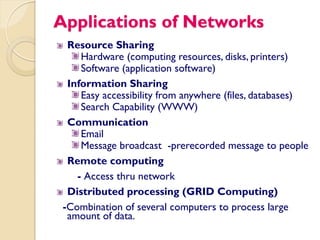
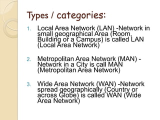
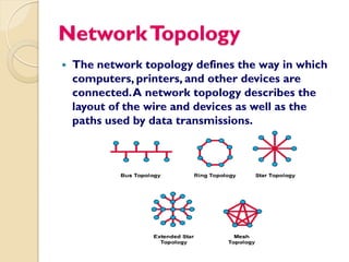
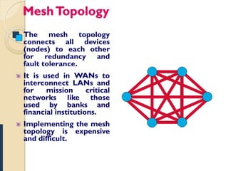
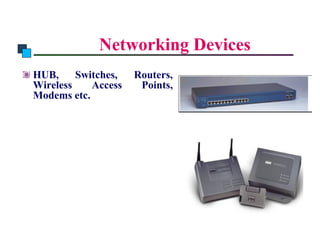
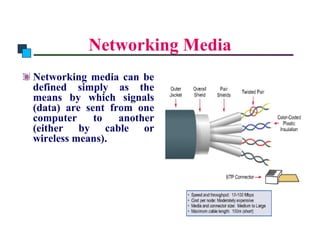
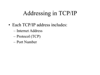
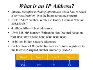


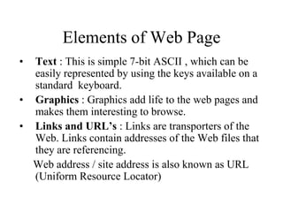

This document provides an overview of computer networks. It defines what a computer network is and discusses how computers connect and share resources over a network. It also covers different types of networks like LAN, MAN, and WAN. Additionally, it describes common network devices like hubs, switches, routers, and gateways. The document also discusses network topologies, transmission media, and addressing in TCP/IP networks. In summary, it serves as a comprehensive introduction to fundamental computer networking concepts.


![Getting Started with Apache Spark: Big Data Made Simple [Free Meetup]](https://cdn.slidesharecdn.com/ss_thumbnails/apachesparkgettingstarted-260203175547-8361bcc3-thumbnail.jpg?width=640&height=640&fit=bounds)


