The document provides information about different network topologies:
- It defines network topology and describes two main types - physical and logical topology. Physical topology refers to how devices are physically connected, while logical topology describes the logical flow of data.
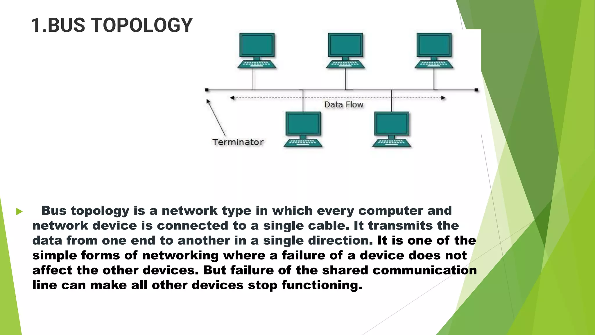
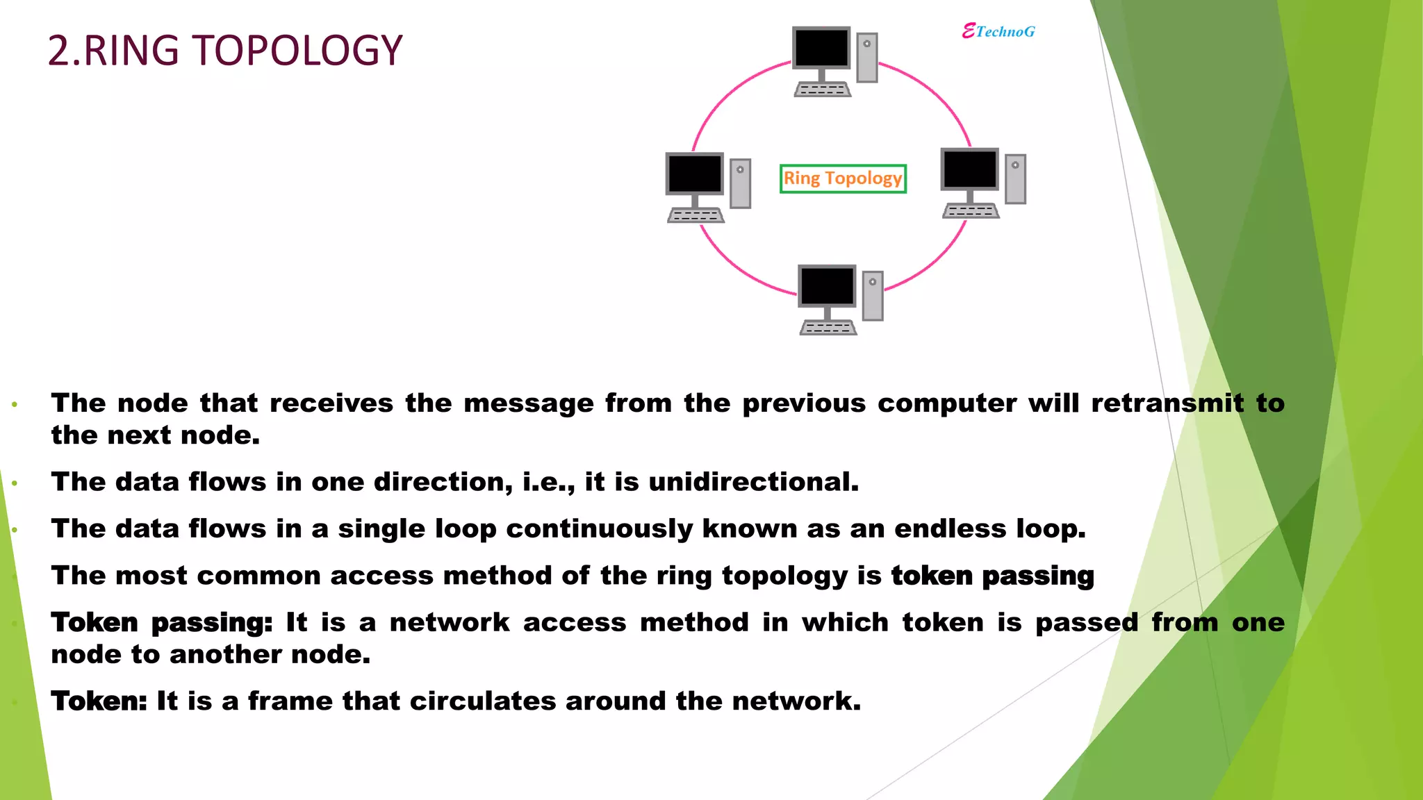
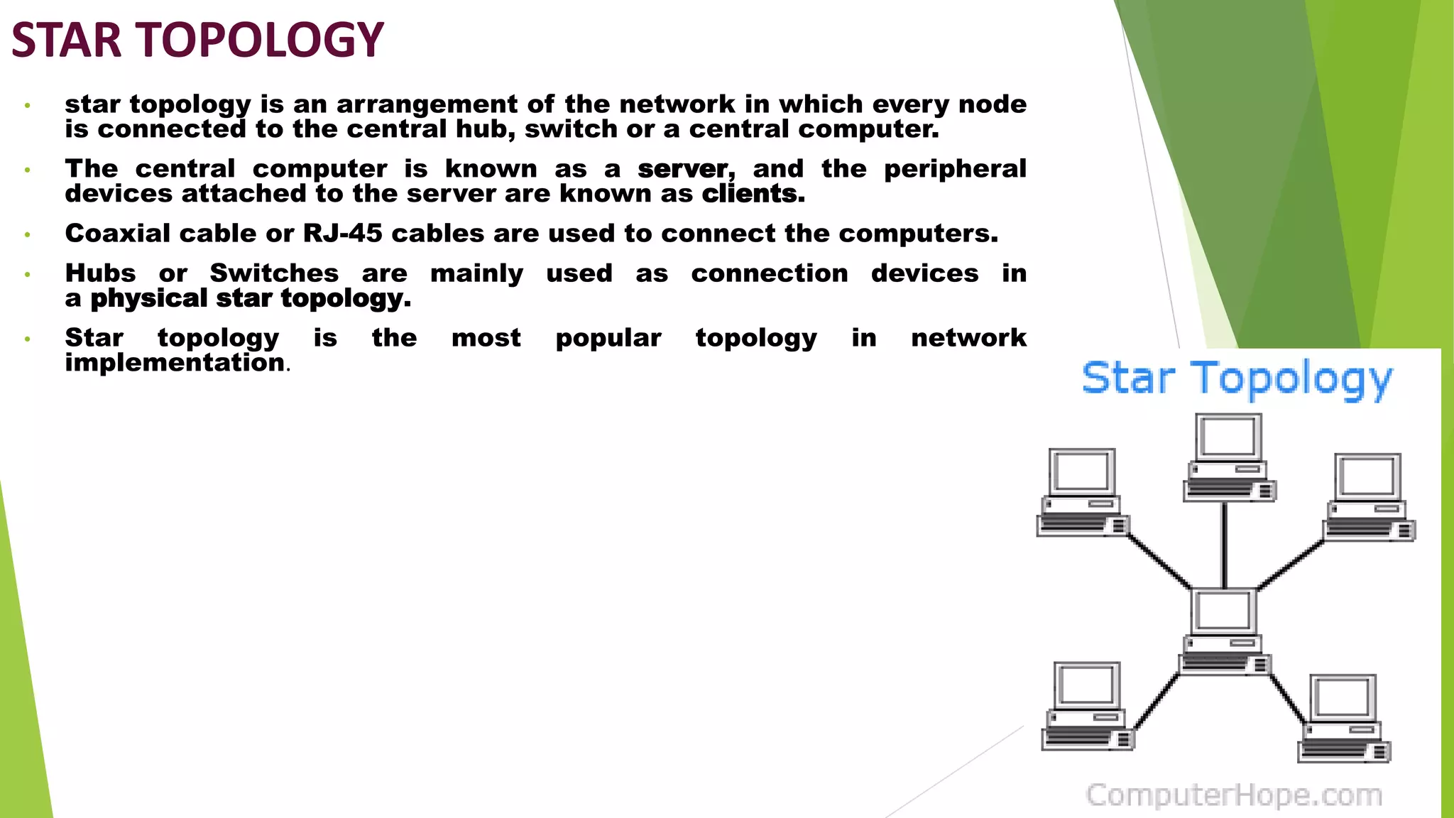
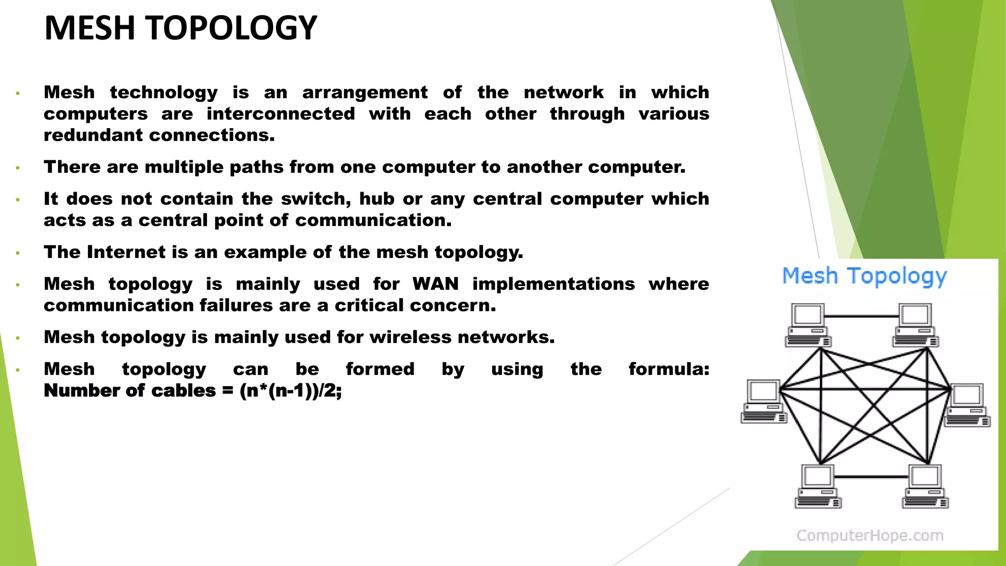
- It discusses several common network topologies - bus, ring, star, mesh and tree - outlining their key characteristics, advantages and disadvantages.
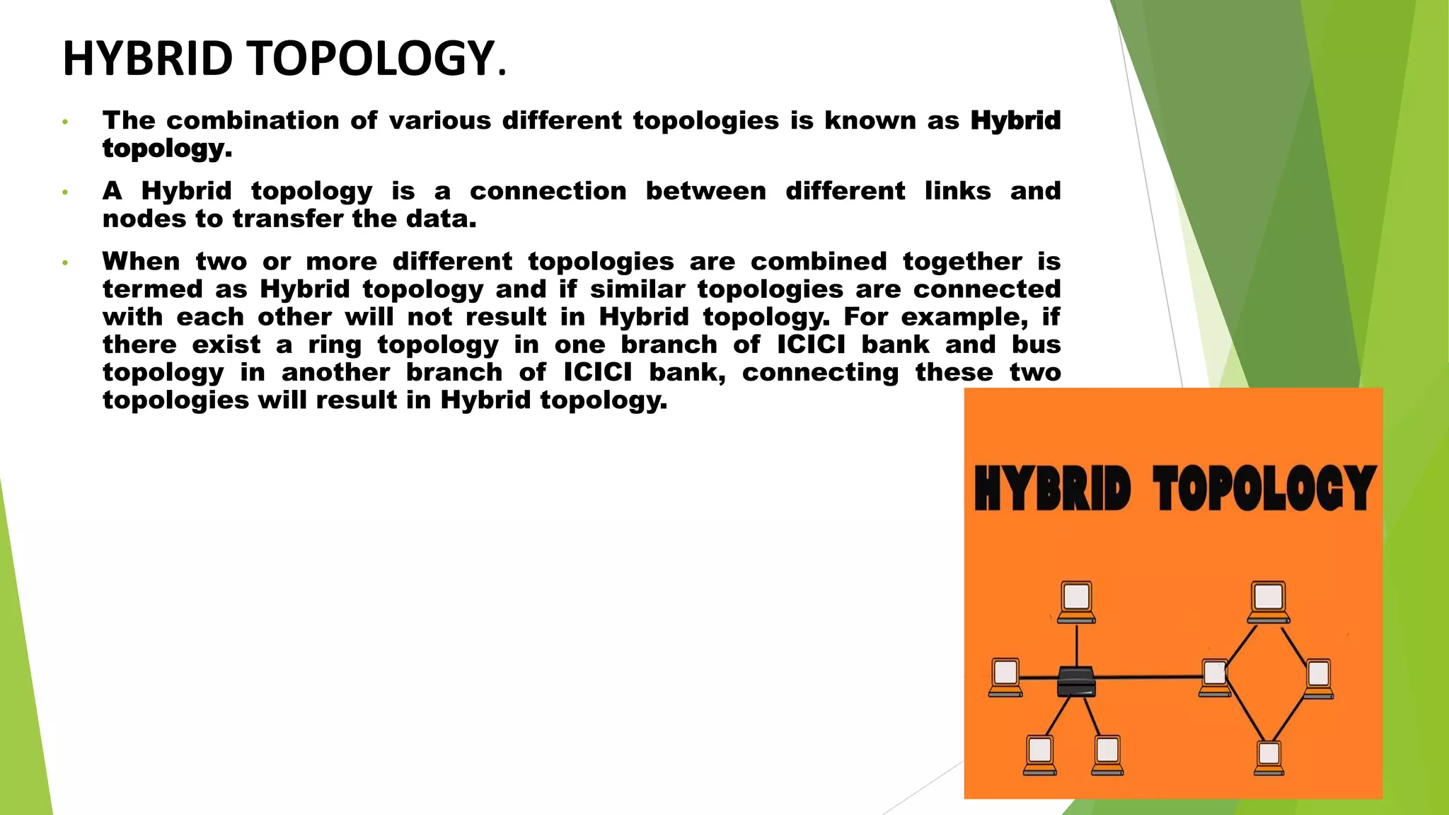
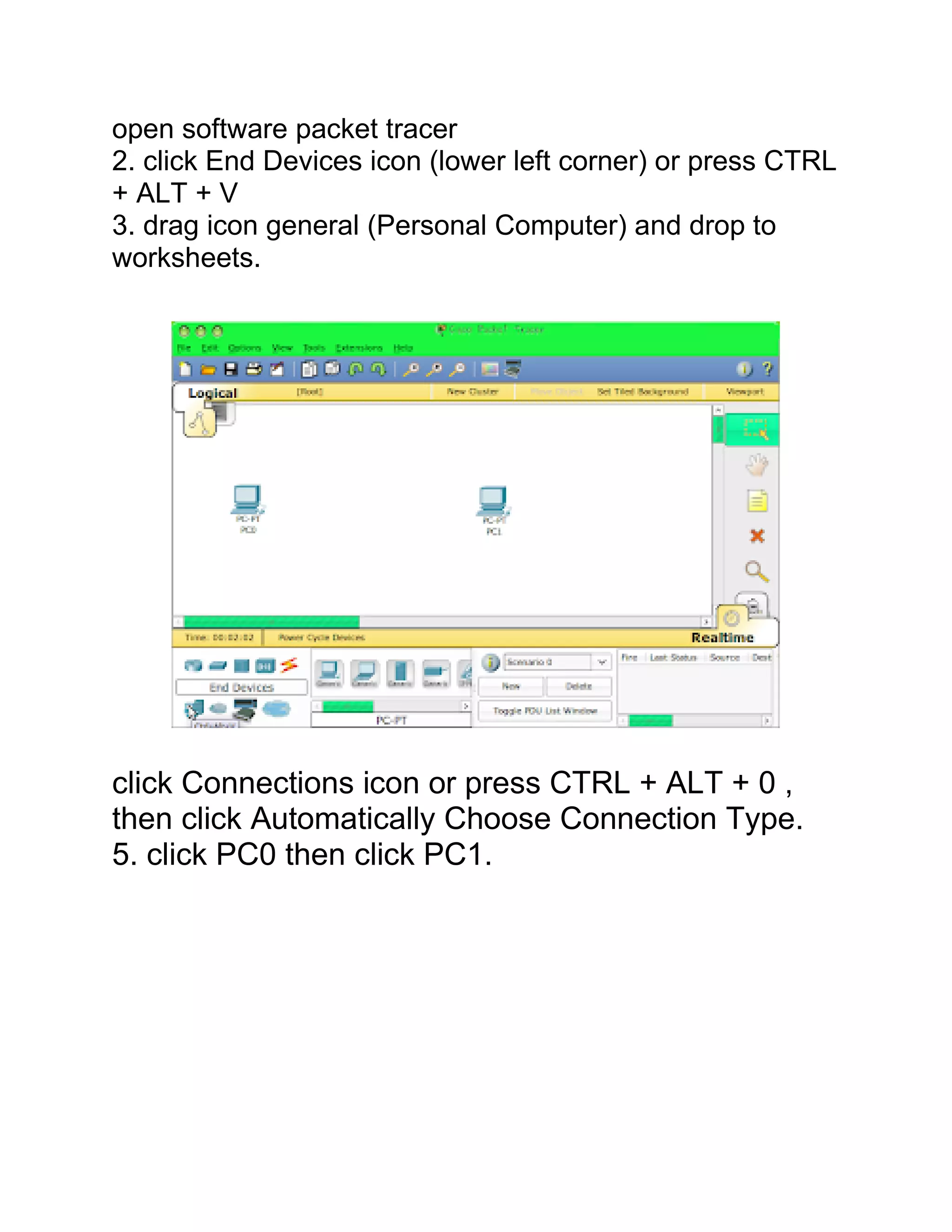
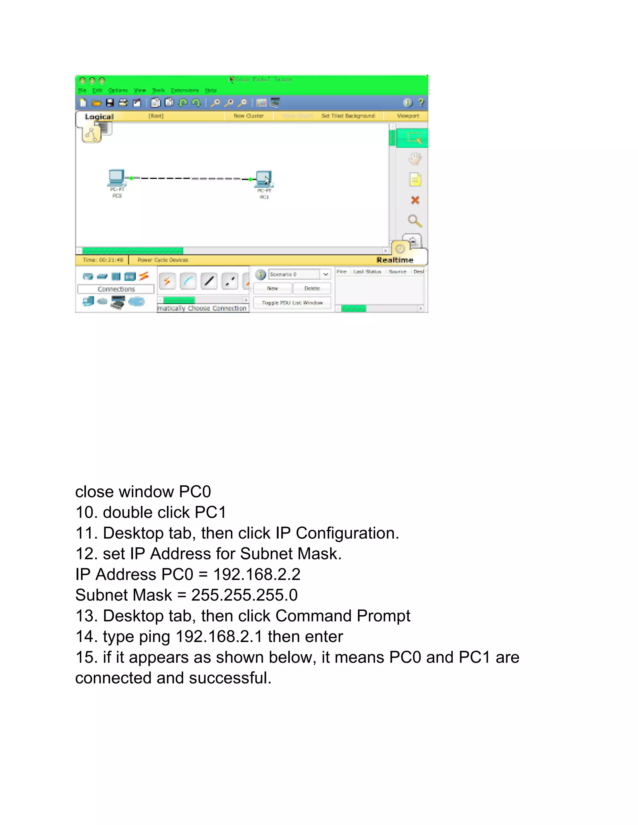
- It also mentions hybrid topology, which is a combination of different topologies, and Packet Tracer, a software tool used to simulate network configurations and devices.


![Vibe Coding vs. Spec-Driven Development [Free Meetup]](https://cdn.slidesharecdn.com/ss_thumbnails/vibecodingvsspecdrivendevelopment-251209105622-43f455e7-thumbnail.jpg?width=640&height=640&fit=bounds)


