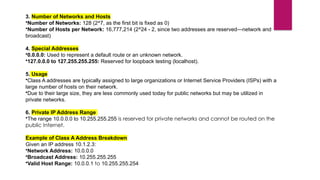
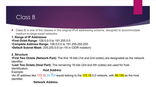
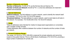
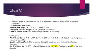
Network Layer
BY TRUPTI SISODE.
What is the Network Layer?
 The network layer is a part of the communication process in computer
networks. Its main job is to move data packets between different networks.
 It helps route these packets from the sender to the receiver across multiple
paths and networks.
 Network-to-network connections enable the Internet to function. These
connections happen at the “network layer,” which sends data packets
between different networks.
 In the 7-layer OSI model, the network layer is layer 3. The Internet Protocol
(IP) is a key protocol used at this layer, along with other protocols for routing,
testing, and encryption.
Features of Network Layer
 The main responsibility of the Network layer is to carry the data packets
from the source to the destination without changing or using them.
 If the packets are too large for delivery, they are fragmented i.e., broken
down into smaller packets.
 It decides the route to be taken by the packets to travel from the source to
the destination among the multiple routes available in a network (also
called routing).
 The source and destination addresses are added to the data packets inside
the network layer.
Services Offered by Network Layer
 1. Packetizing
Packetizing is the process of putting data into a packet at the source and
taking it out of the packet at the destination.
• At the Source: The source puts a header with the source and destination
addresses onto the data, then sends the packet to the next layer.
• At the Destination: The destination receives the packet, removes the
header, and sends the data to the appropriate place.
• Routers: They don’t change the addresses in the packet. They only handle
the packet if it needs to be split into smaller pieces.
1. Packetizing
2. Routing
 Routing is the process of directing data packets from one place to another across a network.
 Example
 Imagine sending a letter from your home to a friend’s house in a different city. Here’s how routing works:
1. Starting Point (Your Home):
1. You write the letter and address it with your friend’s location.
2. Route Taken:
1. The letter is sent to a post office, then to several intermediate locations (like other post offices or sorting centers), each of which figur
2. es out the next destination based on the address.
3. Destination (Friend’s House):
1. Finally, the letter arrives at your friend’s house, where it’s delivered.
 In Short: Routing determines the best path for data to travel across a network from the sender to the receiver, ensuring it
reaches the correct destination efficiently.
Routing
Forwarding
 Forwarding in the network layer is the process of moving data packets from one network device to another along
the path to their final destination.
 Simple Example
 Think of forwarding as a delivery service:
1. Receiving Device (Router): A router receives a packet of data.
2. Checking Destination: The router looks at the packet’s destination address.
3. Sending to Next Device: Based on the address, the router forwards the packet to the next device or router on the
path to the destination.
4. Continuing the Journey: The packet continues to be forwarded from router to router until it reaches its
destination.
 In Short: Forwarding is the action of directing data packets to their next hop or device based on their destination
address, helping them travel through the network.
Forwarding
Other Services Expected from Network
Layer
 Error Control
• Purpose: Detects and manages errors that occur during data transmission.
• How: Uses techniques like checksums or acknowledgments to identify corrupted or lost packets and request
retransmission if needed.
 2. Flow Control
• Purpose: Ensures that data is sent at a rate that the receiving device can handle.
• How: Adjusts the rate of data transmission based on the receiver’s ability to process and store incoming
packets, preventing data overload.
 3. Congestion Control
• Purpose: Prevents network congestion by managing the amount of data entering the network.
• How: Monitors network traffic and adjusts the data flow to avoid excessive load that could slow down or
block the network.
IPv4 addressing
 The IPv4 address is a 32-bit number that uniquely identifies a network
interface on a machine. An IPv4 address is typically written in decimal
digits, formatted as four 8-bit fields that are separated by periods.
1. Address Format:

32-bit Address: An IPv4 address consists of 32 bits. This is divided into four 8-
bit octets. Each octet is represented as a decimal number ranging from 0 to
255.
•Example: 192.168.1.1
Binary Representation: The address can also be represented in binary format,
such as 11000000.10101000.00000001.00000001
Address space
 The address space of IPv4 is 32 bits, which means it can provide approximately
2³² or about 4.3 billion unique addresses. This limitation has led to the adoption
of IPv6, which uses 128 bits and can provide a vastly larger address space.
 The address space of IPv4 is 2^32 or
4,294,967,296
Notations
 Binary Notation In binary notation, the IPv4 address is displayed as 32 bits. Each octet is
often referred to as a byte. So it is common to hear an IPv4 address referred to as a 32-bit
address or a 4-byte address. The following is an example of an IPv4 address in binary
notation:
 01110101 10010101 00011101 00000010
 Dotted-Decimal Notation To make the IPv4 address more compact and easier to read,
Internet addresses are usually written in decimal form with a decimal point (dot)
separating the bytes.
 The following is the dotted decimal notation of the above address: 117.149.29.2
binary notation to dotted-decimal notation
Example
Change the following IPv4 addresses from binary notation to dotted-
decimal notation.
a. 10000001 00001011 00001011 11101111
b. 11000001 10000011 00011011 11111111
Solution We replace each group of 8 bits with its equivalent decimal
number (see Appendix B) and add dots for separation.
a. 129.11.11.239
b. 193.131.27.255
dotted-decimal notation to binary notation.
Find the error
Classful addressing
 Classful addressing is an old method used in IP networking to divide the IP address space
into distinct classes, each catering to different network sizes. This method was part of
IPv4 and helped in allocating IP addresses based on the size of the network.
 In classful addressing, the address space is divided into five classes: A, B, C, D, and E.
•1. 00001000 00101000 00001111 11000011 → Class A (first bit 0)
•2. 10101100 00010000 00001101 00101011 → Class B (first 2 bits 10)
•3. 23.45.67.89 → Class A (first byte 23)
•4. 240.100.200.250 → Class E (first byte 240)
Finding the classes in binary and dotted-decimal notation
Class A
Class A is one of the classes in the IPv4 addressing scheme, used in early network design for IP
addressing.
1. Range of IP Addresses
•First Octet Range: 1.0.0.0 to 126.0.0.0
•Complete Address Range: 1.0.0.0 to 126.255.255.255
•Default Subnet Mask: 255.0.0.0 (or /8 in CIDR notation)
2. Structure
•First Octet (Network Part): The first 8 bits (1st octet) are designated as the network identifier.
•Remaining Octets (Host Part): The remaining 24 bits (2nd, 3rd, and 4th octets) are used for host
identification.
Example:
•An IP address like 10.1.2.3 would belong to the 10.0.0.0 network, with 1.2.3 as the host
identifier.
3. Number of Networks and Hosts
•Number of Networks: 128 (2^7, as the first bit is fixed as 0)
•Number of Hosts per Network: 16,777,214 (2^24 - 2, since two addresses are reserved—network and
broadcast)
4. Special Addresses
•0.0.0.0: Used to represent a default route or an unknown network.
•127.0.0.0 to 127.255.255.255: Reserved for loopback testing (localhost).
5. Usage
•Class A addresses are typically assigned to large organizations or Internet Service Providers (ISPs) with a
large number of hosts on their network.
•Due to their large size, they are less commonly used today for public networks but may be utilized in
private networks.
6. Private IP Address Range
•The range 10.0.0.0 to 10.255.255.255 is reserved for private networks and cannot be routed on the
public Internet.
Example of Class A Address Breakdown
Given an IP address 10.1.2.3:
•Network Address: 10.0.0.0
•Broadcast Address: 10.255.255.255
•Valid Host Range: 10.0.0.1 to 10.255.255.254
Class B
 Class B is one of the classes in the original IPv4 addressing scheme, designed to accommodate
medium to large-sized networks.
1. Range of IP Addresses
•First Octet Range: 128.0.0.0 to 191.255.0.0
•Complete Address Range: 128.0.0.0 to 191.255.255.255
•Default Subnet Mask: 255.255.0.0 (or /16 in CIDR notation)
2. Structure
•First Two Octets (Network Part): The first 16 bits (1st and 2nd octets) are designated as the network
identifier.
•Last Two Octets (Host Part): The remaining 16 bits (3rd and 4th octets) are used for host
identification.
Example:
•An IP address like 172.16.50.100 would belong to the 172.16.0.0 network, with 50.100 as the host
identifier.
Host Address
Network Address
Number of Networks and Hosts
•Number of Networks: 16,384 (2^14, as the first two bits are fixed as 10)
•Number of Hosts per Network: 65,534 (2^16 - 2, since two addresses are reserved—
network and broadcast)
4. Special Addresses
•Network Address: The first address in a given network, used to identify the network itself.
For example, 172.16.0.0 in the 172.16.0.0/16 network.
•Broadcast Address: The last address in a given network, used to send data to all hosts in
the network. For example, 172.16.255.255 in the 172.16.0.0/16 network.
5. Usage
•Class B addresses were intended for medium to large-sized organizations or universities
with a sizable number of hosts.
•These addresses offer a balance between the number of networks and the number of hosts
per network.
6. Private IP Address Range :
The range 172.16.0.0 to 172.31.255.255 is reserved for private networks and cannot be
routed on the public Internet. This is a 20-bit block of addresses (172.16.0.0/12), providing a
large number of addresses for private use.
Class C
 Class C is one of the classes in the IPv4 addressing scheme, designed for small-sized
networks.
1. Range of IP Addresses
•First Octet Range: 192.0.0.0 to 223.255.255.255
•Complete Address Range: 192.0.0.0 to 223.255.255.255
•Default Subnet Mask: 255.255.255.0 (or /24 in CIDR notation)
2. Structure
•First Three Octets (Network Part): The first 24 bits (1st, 2nd, and 3rd octets) are designated as
the network identifier.
•Last Octet (Host Part): The remaining 8 bits (4th octet) are used for host identification.
Example:
•An IP address like 192.168.1.10 would belong to the 192.168.1.0 network, with 10 as the host
identifier.
3. Number of Networks and Hosts
•Number of Networks: 2,097,152 (2^21, as the first three bits are fixed as 110)
•Number of Hosts per Network: 254 (2^8 - 2, since two addresses are reserved—network
and broadcast)
4. Special Addresses
•Network Address: The first address in a given network, used to identify the network itself.
For example, 192.168.1.0 in the 192.168.1.0/24 network.
•Broadcast Address: The last address in a given network, used to send data to all hosts in
the network. For example, 192.168.1.255 in the 192.168.1.0/24 network.
5. Usage
•Class C addresses are primarily intended for small-sized networks, such as small
businesses or home networks.
•Because of the limited number of hosts per network, they are ideal for environments where
fewer than 254 devices are needed.
6. Private IP Address Range
•The range 192.168.0.0 to 192.168.255.255 is reserved for private networks and cannot be
routed on the public Internet. This is a 16-bit block of addresses (192.168.0.0/16), providing a
large number of smaller networks for private use.
Class D
Class D IP addresses are used for multicasting, a method of sending data to a group of destinations simultaneously.
Unlike Classes A, B, and C, which are used for unicast (one-to-one communication), Class D addresses do not
identify individual hosts. Instead, they identify groups of hosts known as multicast groups.
1. Range of IP Addresses
•First Octet Range: 224.0.0.0 to 239.255.255.255
•Complete Address Range: 224.0.0.0 to 239.255.255.255
•Default Subnet Mask: Class D addresses do not have a subnet mask because they are not intended for standard
host-based networking.
2. Structure
•First Four Bits (1110): The first four bits of a Class D address are fixed as 1110, which determines that the
address is within the multicast range.
•Remaining 28 Bits: The remaining 28 bits identify the specific multicast group.
Example:
•An IP address like 224.0.1.1 is a multicast address, with the specific group identified by the remaining 28 bits.
•Class D addresses are reserved for multicast groups, not for individual hosts or networks.
•They allow efficient data distribution to multiple recipients simultaneously, making them ideal for applications like live
streaming, online gaming, and real-time data feeds.
•Class D addresses span the range 224.0.0.0 to 239.255.255.255 and are managed differently from the traditional
unicast addresses in Classes A, B, and C.
Class E
 Class E IP addresses are reserved for experimental purposes and are not used in regular network
operations.
 The address range 240.0.0.0 to 255.255.255.255 is not available for public or private network
assignments.
 These addresses are generally ignored by networking devices and protocols, except for specific
research and experimental use cases.
1. Range of IP Addresses
•First Octet Range: 240.0.0.0 to 255.255.255.255
•Complete Address Range: 240.0.0.0 to 255.255.255.255
2. Structure
•First Four Bits (1111): The first four bits of a Class E address are fixed as 1111, which places the
address within the reserved range.
•Remaining 28 Bits: The remaining 28 bits could theoretically be used for network and host
identification, but Class E addresses are not defined for use in standard networking.

Network layer in computer networks .pptx

  • 1.
  • 2.
    What is theNetwork Layer?  The network layer is a part of the communication process in computer networks. Its main job is to move data packets between different networks.  It helps route these packets from the sender to the receiver across multiple paths and networks.  Network-to-network connections enable the Internet to function. These connections happen at the “network layer,” which sends data packets between different networks.  In the 7-layer OSI model, the network layer is layer 3. The Internet Protocol (IP) is a key protocol used at this layer, along with other protocols for routing, testing, and encryption.
  • 3.
    Features of NetworkLayer  The main responsibility of the Network layer is to carry the data packets from the source to the destination without changing or using them.  If the packets are too large for delivery, they are fragmented i.e., broken down into smaller packets.  It decides the route to be taken by the packets to travel from the source to the destination among the multiple routes available in a network (also called routing).  The source and destination addresses are added to the data packets inside the network layer.
  • 4.
    Services Offered byNetwork Layer  1. Packetizing Packetizing is the process of putting data into a packet at the source and taking it out of the packet at the destination. • At the Source: The source puts a header with the source and destination addresses onto the data, then sends the packet to the next layer. • At the Destination: The destination receives the packet, removes the header, and sends the data to the appropriate place. • Routers: They don’t change the addresses in the packet. They only handle the packet if it needs to be split into smaller pieces.
  • 5.
  • 6.
    2. Routing  Routingis the process of directing data packets from one place to another across a network.  Example  Imagine sending a letter from your home to a friend’s house in a different city. Here’s how routing works: 1. Starting Point (Your Home): 1. You write the letter and address it with your friend’s location. 2. Route Taken: 1. The letter is sent to a post office, then to several intermediate locations (like other post offices or sorting centers), each of which figur 2. es out the next destination based on the address. 3. Destination (Friend’s House): 1. Finally, the letter arrives at your friend’s house, where it’s delivered.  In Short: Routing determines the best path for data to travel across a network from the sender to the receiver, ensuring it reaches the correct destination efficiently.
  • 7.
  • 8.
    Forwarding  Forwarding inthe network layer is the process of moving data packets from one network device to another along the path to their final destination.  Simple Example  Think of forwarding as a delivery service: 1. Receiving Device (Router): A router receives a packet of data. 2. Checking Destination: The router looks at the packet’s destination address. 3. Sending to Next Device: Based on the address, the router forwards the packet to the next device or router on the path to the destination. 4. Continuing the Journey: The packet continues to be forwarded from router to router until it reaches its destination.  In Short: Forwarding is the action of directing data packets to their next hop or device based on their destination address, helping them travel through the network.
  • 9.
  • 10.
    Other Services Expectedfrom Network Layer  Error Control • Purpose: Detects and manages errors that occur during data transmission. • How: Uses techniques like checksums or acknowledgments to identify corrupted or lost packets and request retransmission if needed.  2. Flow Control • Purpose: Ensures that data is sent at a rate that the receiving device can handle. • How: Adjusts the rate of data transmission based on the receiver’s ability to process and store incoming packets, preventing data overload.  3. Congestion Control • Purpose: Prevents network congestion by managing the amount of data entering the network. • How: Monitors network traffic and adjusts the data flow to avoid excessive load that could slow down or block the network.
  • 11.
    IPv4 addressing  TheIPv4 address is a 32-bit number that uniquely identifies a network interface on a machine. An IPv4 address is typically written in decimal digits, formatted as four 8-bit fields that are separated by periods. 1. Address Format:  32-bit Address: An IPv4 address consists of 32 bits. This is divided into four 8- bit octets. Each octet is represented as a decimal number ranging from 0 to 255. •Example: 192.168.1.1 Binary Representation: The address can also be represented in binary format, such as 11000000.10101000.00000001.00000001
  • 12.
    Address space  Theaddress space of IPv4 is 32 bits, which means it can provide approximately 2³² or about 4.3 billion unique addresses. This limitation has led to the adoption of IPv6, which uses 128 bits and can provide a vastly larger address space.  The address space of IPv4 is 2^32 or 4,294,967,296
  • 13.
    Notations  Binary NotationIn binary notation, the IPv4 address is displayed as 32 bits. Each octet is often referred to as a byte. So it is common to hear an IPv4 address referred to as a 32-bit address or a 4-byte address. The following is an example of an IPv4 address in binary notation:  01110101 10010101 00011101 00000010  Dotted-Decimal Notation To make the IPv4 address more compact and easier to read, Internet addresses are usually written in decimal form with a decimal point (dot) separating the bytes.  The following is the dotted decimal notation of the above address: 117.149.29.2
  • 15.
    binary notation todotted-decimal notation Example Change the following IPv4 addresses from binary notation to dotted- decimal notation. a. 10000001 00001011 00001011 11101111 b. 11000001 10000011 00011011 11111111 Solution We replace each group of 8 bits with its equivalent decimal number (see Appendix B) and add dots for separation. a. 129.11.11.239 b. 193.131.27.255
  • 16.
  • 17.
  • 18.
    Classful addressing  Classfuladdressing is an old method used in IP networking to divide the IP address space into distinct classes, each catering to different network sizes. This method was part of IPv4 and helped in allocating IP addresses based on the size of the network.  In classful addressing, the address space is divided into five classes: A, B, C, D, and E.
  • 20.
    •1. 00001000 0010100000001111 11000011 → Class A (first bit 0) •2. 10101100 00010000 00001101 00101011 → Class B (first 2 bits 10) •3. 23.45.67.89 → Class A (first byte 23) •4. 240.100.200.250 → Class E (first byte 240)
  • 21.
    Finding the classesin binary and dotted-decimal notation
  • 22.
    Class A Class Ais one of the classes in the IPv4 addressing scheme, used in early network design for IP addressing. 1. Range of IP Addresses •First Octet Range: 1.0.0.0 to 126.0.0.0 •Complete Address Range: 1.0.0.0 to 126.255.255.255 •Default Subnet Mask: 255.0.0.0 (or /8 in CIDR notation) 2. Structure •First Octet (Network Part): The first 8 bits (1st octet) are designated as the network identifier. •Remaining Octets (Host Part): The remaining 24 bits (2nd, 3rd, and 4th octets) are used for host identification. Example: •An IP address like 10.1.2.3 would belong to the 10.0.0.0 network, with 1.2.3 as the host identifier.
  • 23.
    3. Number ofNetworks and Hosts •Number of Networks: 128 (2^7, as the first bit is fixed as 0) •Number of Hosts per Network: 16,777,214 (2^24 - 2, since two addresses are reserved—network and broadcast) 4. Special Addresses •0.0.0.0: Used to represent a default route or an unknown network. •127.0.0.0 to 127.255.255.255: Reserved for loopback testing (localhost). 5. Usage •Class A addresses are typically assigned to large organizations or Internet Service Providers (ISPs) with a large number of hosts on their network. •Due to their large size, they are less commonly used today for public networks but may be utilized in private networks. 6. Private IP Address Range •The range 10.0.0.0 to 10.255.255.255 is reserved for private networks and cannot be routed on the public Internet. Example of Class A Address Breakdown Given an IP address 10.1.2.3: •Network Address: 10.0.0.0 •Broadcast Address: 10.255.255.255 •Valid Host Range: 10.0.0.1 to 10.255.255.254
  • 24.
    Class B  ClassB is one of the classes in the original IPv4 addressing scheme, designed to accommodate medium to large-sized networks. 1. Range of IP Addresses •First Octet Range: 128.0.0.0 to 191.255.0.0 •Complete Address Range: 128.0.0.0 to 191.255.255.255 •Default Subnet Mask: 255.255.0.0 (or /16 in CIDR notation) 2. Structure •First Two Octets (Network Part): The first 16 bits (1st and 2nd octets) are designated as the network identifier. •Last Two Octets (Host Part): The remaining 16 bits (3rd and 4th octets) are used for host identification. Example: •An IP address like 172.16.50.100 would belong to the 172.16.0.0 network, with 50.100 as the host identifier. Host Address Network Address
  • 25.
    Number of Networksand Hosts •Number of Networks: 16,384 (2^14, as the first two bits are fixed as 10) •Number of Hosts per Network: 65,534 (2^16 - 2, since two addresses are reserved— network and broadcast) 4. Special Addresses •Network Address: The first address in a given network, used to identify the network itself. For example, 172.16.0.0 in the 172.16.0.0/16 network. •Broadcast Address: The last address in a given network, used to send data to all hosts in the network. For example, 172.16.255.255 in the 172.16.0.0/16 network. 5. Usage •Class B addresses were intended for medium to large-sized organizations or universities with a sizable number of hosts. •These addresses offer a balance between the number of networks and the number of hosts per network. 6. Private IP Address Range : The range 172.16.0.0 to 172.31.255.255 is reserved for private networks and cannot be routed on the public Internet. This is a 20-bit block of addresses (172.16.0.0/12), providing a large number of addresses for private use.
  • 26.
    Class C  ClassC is one of the classes in the IPv4 addressing scheme, designed for small-sized networks. 1. Range of IP Addresses •First Octet Range: 192.0.0.0 to 223.255.255.255 •Complete Address Range: 192.0.0.0 to 223.255.255.255 •Default Subnet Mask: 255.255.255.0 (or /24 in CIDR notation) 2. Structure •First Three Octets (Network Part): The first 24 bits (1st, 2nd, and 3rd octets) are designated as the network identifier. •Last Octet (Host Part): The remaining 8 bits (4th octet) are used for host identification. Example: •An IP address like 192.168.1.10 would belong to the 192.168.1.0 network, with 10 as the host identifier.
  • 27.
    3. Number ofNetworks and Hosts •Number of Networks: 2,097,152 (2^21, as the first three bits are fixed as 110) •Number of Hosts per Network: 254 (2^8 - 2, since two addresses are reserved—network and broadcast) 4. Special Addresses •Network Address: The first address in a given network, used to identify the network itself. For example, 192.168.1.0 in the 192.168.1.0/24 network. •Broadcast Address: The last address in a given network, used to send data to all hosts in the network. For example, 192.168.1.255 in the 192.168.1.0/24 network. 5. Usage •Class C addresses are primarily intended for small-sized networks, such as small businesses or home networks. •Because of the limited number of hosts per network, they are ideal for environments where fewer than 254 devices are needed. 6. Private IP Address Range •The range 192.168.0.0 to 192.168.255.255 is reserved for private networks and cannot be routed on the public Internet. This is a 16-bit block of addresses (192.168.0.0/16), providing a large number of smaller networks for private use.
  • 28.
    Class D Class DIP addresses are used for multicasting, a method of sending data to a group of destinations simultaneously. Unlike Classes A, B, and C, which are used for unicast (one-to-one communication), Class D addresses do not identify individual hosts. Instead, they identify groups of hosts known as multicast groups. 1. Range of IP Addresses •First Octet Range: 224.0.0.0 to 239.255.255.255 •Complete Address Range: 224.0.0.0 to 239.255.255.255 •Default Subnet Mask: Class D addresses do not have a subnet mask because they are not intended for standard host-based networking. 2. Structure •First Four Bits (1110): The first four bits of a Class D address are fixed as 1110, which determines that the address is within the multicast range. •Remaining 28 Bits: The remaining 28 bits identify the specific multicast group. Example: •An IP address like 224.0.1.1 is a multicast address, with the specific group identified by the remaining 28 bits. •Class D addresses are reserved for multicast groups, not for individual hosts or networks. •They allow efficient data distribution to multiple recipients simultaneously, making them ideal for applications like live streaming, online gaming, and real-time data feeds. •Class D addresses span the range 224.0.0.0 to 239.255.255.255 and are managed differently from the traditional unicast addresses in Classes A, B, and C.
  • 29.
    Class E  ClassE IP addresses are reserved for experimental purposes and are not used in regular network operations.  The address range 240.0.0.0 to 255.255.255.255 is not available for public or private network assignments.  These addresses are generally ignored by networking devices and protocols, except for specific research and experimental use cases. 1. Range of IP Addresses •First Octet Range: 240.0.0.0 to 255.255.255.255 •Complete Address Range: 240.0.0.0 to 255.255.255.255 2. Structure •First Four Bits (1111): The first four bits of a Class E address are fixed as 1111, which places the address within the reserved range. •Remaining 28 Bits: The remaining 28 bits could theoretically be used for network and host identification, but Class E addresses are not defined for use in standard networking.