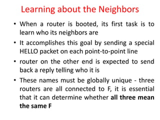
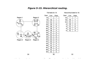
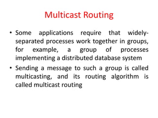
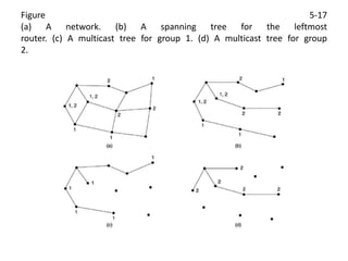
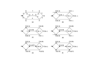
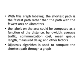
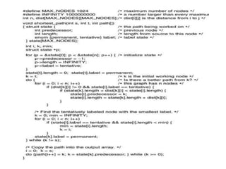
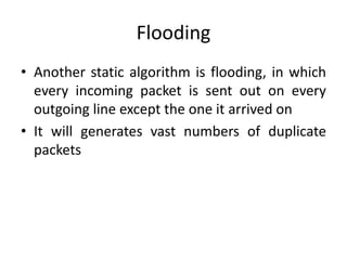
NETWORK LAYER
• The network layer is concerned with getting
packets from the source all the way to the
destination
• network layer is the lowest layer that deals
with end-to-end transmission
Routing Algorithms
• The main function of the network layer is
routing packets from the source machine to
the destination machine
• In most subnets, packets will require multiple
hops to make the journey
• The algorithms that choose the routes and the
data structures that they use are a major area
of network layer design
• The routing algorithm is that part of the network layer
software responsible for deciding which output line an
incoming packet should be transmitted on
• If the subnet uses datagrams internally, this decision
must be made a new for every arriving data packet
• since the best route may have changed since last time.
• If the subnet uses virtual circuits internally, routing
decisions are made only when a new virtual circuit is
being set up.
• Data packets just follow the previously-established
route. The latter case is sometimes called session
routing because a route remains in force for an entire
user session
• It is sometimes useful to make a distinction
between routing, which is making the decision
which routes to use, and forwarding, which is
what happens when a packet arrives
• This process is forwarding
• The other process is responsible for filling in
and updating the routing tables
• That is where the routing algorithm comes
into play
• Properties in a routing algorithm are,
• correctness, simplicity, robustness, stability,
fairness, and optimality
• fairness -according to the law, rules
• optimality - most desirable
• Conflict between fairness and optimality
• Suppose that there is enough traffic between A
and A', between B and B', and between C and C'
to saturate the horizontal links
• To maximize the total flow, the X to X' traffic
should be shut off altogether
• Unfortunately, X and X' may not see it that way
• Evidently, some compromise between global
efficiency and fairness to individual connections
is needed
The Optimality Principle
• one can make a general statement about
optimal routes without regard to network
topology or traffic.
• This statement is known as the optimality
principle
• It states that if router J is on the optimal path
from router I to router K, then the optimal
path from J to K also falls along the same
route
• As a direct consequence of the optimality
principle, we can see that the set of optimal
routes from all sources to a given destination
form a tree rooted at the destination.
• Such a tree is called a sink tree
• Figure (a) A subnet. (b) A sink tree for router B
Shortest Path Routing
• The idea is to build a graph of the subnet, with
each node of the graph representing a router
and each arc of the graph representing a
communication line (often called a link)
• To choose a route between a given pair of
routers, the algorithm just finds the shortest
path between them on the graph
• One way of measuring path length is the
number of hops
• Using this metric, the paths ABC and ABE in
Fig. 5-7 are equally long
• Another metric is the geographic distance in
kilometers, in which case ABC is clearly much
longer than ABE
• The first five steps used in computing the
shortest path from A to D
• The arrows indicate the working node
• With this graph labeling, the shortest path is
the fastest path rather than the path with the
fewest arcs or kilometers
• the labels on the arcs could be computed as a
function of the distance, bandwidth, average
traffic, communication cost, mean queue
length, measured delay, and other factors
• Dijkstra's algorithm is used to compute the
shortest path through a graph
Flooding
• Another static algorithm is flooding, in which
every incoming packet is sent out on every
outgoing line except the one it arrived on
• It will generates vast numbers of duplicate
packets
• For that 1. we have a hop counter contained in
the header of each packet, which is
decremented at each hop, with the packet
being discarded when the counter reaches
zero
• 2. Is to keep track of which packets have been
flooded, to avoid sending them out a second
time. For this maintain sequence number in
each packet
• If an incoming packet is on the list, it is not
flooded
• selective flooding - routers do not send every
incoming packet out on every line, only on
those lines that are going approximately in the
right direction
• Flooding is more useful in,
– Military Applications
– Distributed Database Applications
– Wireless Networks
Distance Vector Routing
• Modern computer networks generally use
dynamic routing algorithms rather than the
static ones
• static algorithms do not take the current
network load into account
• Two dynamic algorithms,
– Distance Vector Routing
– Link State Routing
• Distance vector routing algorithms operate by
having each router maintain a table (i.e, a
vector) giving the best known distance to each
destination
• These tables are updated by exchanging
information with the neighbors
• The distance vector routing algorithm or
distributed Bellman-Ford routing algorithm
and the Ford-Fulkerson algorithm developed
by Bellman, 1957; and Ford and Fulkerson,
1962
• In distance vector routing [4,7, 9, 10] each
router collects and forwards the information
from and to the neighbors
• It was the original ARPANET routing algorithm
and was also used in the Internet under the
name RIP
• Consider how J computes its new route to
router G.
• It knows that it can get to A in 8 msec, and A
claims to be able to get to G in 18 msec, so J
knows it can count on a delay of 26 msec to G
if it forwards packets bound for G to A
Link State Routing
• First, since the delay metric was queue length,
it did not take line bandwidth into account
when choosing routes.
• second problem also existed, namely, the
algorithm often took too long to converge (the
count-to-infinity problem)
• For these reasons, it was replaced by an
entirely new algorithm, now called link state
routing
The idea behind link state routing
are,
• 1. Discover its neighbors and learn their
network addresses
• 2. Measure the delay or cost to each of its
neighbors
• 3. Construct a packet telling all it has just
learned
• 4. Send this packet to all other routers
• 5. Compute the shortest path to every other
router
Learning about the Neighbors
• When a router is booted, its first task is to
learn who its neighbors are
• It accomplishes this goal by sending a special
HELLO packet on each point-to-point line
• router on the other end is expected to send
back a reply telling who it is
• These names must be globally unique - three
routers are all connected to F, it is essential
that it can determine whether all three mean
the same F
• When two or more routers are connected by a
LAN, the situation is slightly more
complicated.
• Fig. 5-11(a) illustrates a LAN to which three
routers, A, C, and F, are directly connected.
• One way to model the LAN is to consider it as
a node itself, as shown in Fig. 5-11(b)
• Here we have introduced a new, artificial
node, N, to which A, C, and F are connected
• The fact that it is possible to go from A to C on
the LAN is represented by the path ANC here
Hierarchical Routing
• As networks grow in size, the router routing
tables grow proportionally
• When hierarchical routing is used, the routers
are divided into regions
• each router knowing all the details about how
to route packets to destinations within its own
region, but knowing nothing about the
internal structure of other regions
• The full routing table for router 1A has 17
entries, as shown in Fig. 5-15(b)
• When routing is done hierarchically, as in Fig.
5-15(c), there are entries for all the local
routers as before, but all other regions have
been condensed into a single router,
• region 2 goes via the 1B -2A line, via the 1C -
3B line
• Hierarchical routing has reduced the table
from 17 to 7 entries
Broadcast Routing
• In some applications, hosts need to send
messages to many or all other hosts
• Example: a service distributing weather
reports, stock market updates, or live radio
programs might work best by broadcasting to
all machines
• Sending a packet to all destinations
simultaneously is called broadcasting
• A third algorithm is multidestination routing
• If this method is used, each packet contains
either a list of destinations
• When a packet arrives at a router, the router
checks all the destinations to determine the
set of output lines that will be needed
• Multidestination routing is like separately
addressed packets, except that when several
packets must follow the same route, one of
them pays full fare and the rest ride free
• Our last broadcast algorithm is an attempt to
approximate the behavior of the previous one, even
when the routers do not know anything at all about
spanning trees
• The idea, called reverse path forwarding
• FIG 5-16. Reverse path forwarding. (a) A subnet. (b) A
sink tree. (c) The tree built by reverse path
forwarding
Multicast Routing
• Some applications require that widely-
separated processes work together in groups,
for example, a group of processes
implementing a distributed database system
• Sending a message to such a group is called
multicasting, and its routing algorithm is
called multicast routing
Figure 5-17
(a) A network. (b) A spanning tree for the leftmost
router. (c) A multicast tree for group 1. (d) A multicast tree for group
2.

NETWORK LAYER.ppt

  • 1.
  • 2.
    • The networklayer is concerned with getting packets from the source all the way to the destination • network layer is the lowest layer that deals with end-to-end transmission
  • 3.
    Routing Algorithms • Themain function of the network layer is routing packets from the source machine to the destination machine • In most subnets, packets will require multiple hops to make the journey • The algorithms that choose the routes and the data structures that they use are a major area of network layer design
  • 4.
    • The routingalgorithm is that part of the network layer software responsible for deciding which output line an incoming packet should be transmitted on • If the subnet uses datagrams internally, this decision must be made a new for every arriving data packet • since the best route may have changed since last time. • If the subnet uses virtual circuits internally, routing decisions are made only when a new virtual circuit is being set up. • Data packets just follow the previously-established route. The latter case is sometimes called session routing because a route remains in force for an entire user session
  • 5.
    • It issometimes useful to make a distinction between routing, which is making the decision which routes to use, and forwarding, which is what happens when a packet arrives • This process is forwarding • The other process is responsible for filling in and updating the routing tables • That is where the routing algorithm comes into play • Properties in a routing algorithm are, • correctness, simplicity, robustness, stability, fairness, and optimality
  • 6.
    • fairness -accordingto the law, rules • optimality - most desirable • Conflict between fairness and optimality
  • 7.
    • Suppose thatthere is enough traffic between A and A', between B and B', and between C and C' to saturate the horizontal links • To maximize the total flow, the X to X' traffic should be shut off altogether • Unfortunately, X and X' may not see it that way • Evidently, some compromise between global efficiency and fairness to individual connections is needed
  • 8.
    The Optimality Principle •one can make a general statement about optimal routes without regard to network topology or traffic. • This statement is known as the optimality principle • It states that if router J is on the optimal path from router I to router K, then the optimal path from J to K also falls along the same route
  • 9.
    • As adirect consequence of the optimality principle, we can see that the set of optimal routes from all sources to a given destination form a tree rooted at the destination. • Such a tree is called a sink tree • Figure (a) A subnet. (b) A sink tree for router B
  • 10.
    Shortest Path Routing •The idea is to build a graph of the subnet, with each node of the graph representing a router and each arc of the graph representing a communication line (often called a link) • To choose a route between a given pair of routers, the algorithm just finds the shortest path between them on the graph
  • 11.
    • One wayof measuring path length is the number of hops • Using this metric, the paths ABC and ABE in Fig. 5-7 are equally long • Another metric is the geographic distance in kilometers, in which case ABC is clearly much longer than ABE • The first five steps used in computing the shortest path from A to D • The arrows indicate the working node
  • 13.
    • With thisgraph labeling, the shortest path is the fastest path rather than the path with the fewest arcs or kilometers • the labels on the arcs could be computed as a function of the distance, bandwidth, average traffic, communication cost, mean queue length, measured delay, and other factors • Dijkstra's algorithm is used to compute the shortest path through a graph
  • 15.
    Flooding • Another staticalgorithm is flooding, in which every incoming packet is sent out on every outgoing line except the one it arrived on • It will generates vast numbers of duplicate packets
  • 16.
    • For that1. we have a hop counter contained in the header of each packet, which is decremented at each hop, with the packet being discarded when the counter reaches zero • 2. Is to keep track of which packets have been flooded, to avoid sending them out a second time. For this maintain sequence number in each packet • If an incoming packet is on the list, it is not flooded
  • 17.
    • selective flooding- routers do not send every incoming packet out on every line, only on those lines that are going approximately in the right direction • Flooding is more useful in, – Military Applications – Distributed Database Applications – Wireless Networks
  • 18.
    Distance Vector Routing •Modern computer networks generally use dynamic routing algorithms rather than the static ones • static algorithms do not take the current network load into account • Two dynamic algorithms, – Distance Vector Routing – Link State Routing
  • 19.
    • Distance vectorrouting algorithms operate by having each router maintain a table (i.e, a vector) giving the best known distance to each destination • These tables are updated by exchanging information with the neighbors • The distance vector routing algorithm or distributed Bellman-Ford routing algorithm and the Ford-Fulkerson algorithm developed by Bellman, 1957; and Ford and Fulkerson, 1962
  • 20.
    • In distancevector routing [4,7, 9, 10] each router collects and forwards the information from and to the neighbors
  • 21.
    • It wasthe original ARPANET routing algorithm and was also used in the Internet under the name RIP
  • 22.
    • Consider howJ computes its new route to router G. • It knows that it can get to A in 8 msec, and A claims to be able to get to G in 18 msec, so J knows it can count on a delay of 26 msec to G if it forwards packets bound for G to A
  • 23.
    Link State Routing •First, since the delay metric was queue length, it did not take line bandwidth into account when choosing routes. • second problem also existed, namely, the algorithm often took too long to converge (the count-to-infinity problem) • For these reasons, it was replaced by an entirely new algorithm, now called link state routing
  • 24.
    The idea behindlink state routing are, • 1. Discover its neighbors and learn their network addresses • 2. Measure the delay or cost to each of its neighbors • 3. Construct a packet telling all it has just learned • 4. Send this packet to all other routers • 5. Compute the shortest path to every other router
  • 25.
    Learning about theNeighbors • When a router is booted, its first task is to learn who its neighbors are • It accomplishes this goal by sending a special HELLO packet on each point-to-point line • router on the other end is expected to send back a reply telling who it is • These names must be globally unique - three routers are all connected to F, it is essential that it can determine whether all three mean the same F
  • 26.
    • When twoor more routers are connected by a LAN, the situation is slightly more complicated. • Fig. 5-11(a) illustrates a LAN to which three routers, A, C, and F, are directly connected.
  • 27.
    • One wayto model the LAN is to consider it as a node itself, as shown in Fig. 5-11(b) • Here we have introduced a new, artificial node, N, to which A, C, and F are connected • The fact that it is possible to go from A to C on the LAN is represented by the path ANC here
  • 28.
    Hierarchical Routing • Asnetworks grow in size, the router routing tables grow proportionally • When hierarchical routing is used, the routers are divided into regions • each router knowing all the details about how to route packets to destinations within its own region, but knowing nothing about the internal structure of other regions
  • 30.
    • The fullrouting table for router 1A has 17 entries, as shown in Fig. 5-15(b) • When routing is done hierarchically, as in Fig. 5-15(c), there are entries for all the local routers as before, but all other regions have been condensed into a single router, • region 2 goes via the 1B -2A line, via the 1C - 3B line • Hierarchical routing has reduced the table from 17 to 7 entries
  • 31.
    Broadcast Routing • Insome applications, hosts need to send messages to many or all other hosts • Example: a service distributing weather reports, stock market updates, or live radio programs might work best by broadcasting to all machines • Sending a packet to all destinations simultaneously is called broadcasting
  • 32.
    • A thirdalgorithm is multidestination routing • If this method is used, each packet contains either a list of destinations • When a packet arrives at a router, the router checks all the destinations to determine the set of output lines that will be needed • Multidestination routing is like separately addressed packets, except that when several packets must follow the same route, one of them pays full fare and the rest ride free
  • 33.
    • Our lastbroadcast algorithm is an attempt to approximate the behavior of the previous one, even when the routers do not know anything at all about spanning trees • The idea, called reverse path forwarding • FIG 5-16. Reverse path forwarding. (a) A subnet. (b) A sink tree. (c) The tree built by reverse path forwarding
  • 34.
    Multicast Routing • Someapplications require that widely- separated processes work together in groups, for example, a group of processes implementing a distributed database system • Sending a message to such a group is called multicasting, and its routing algorithm is called multicast routing
  • 35.
    Figure 5-17 (a) Anetwork. (b) A spanning tree for the leftmost router. (c) A multicast tree for group 1. (d) A multicast tree for group 2.