SlideShare a Scribd company logo
1 of 12
Download to read offline
Vikas V. Gad. Int. Journal of Engineering Research and Application www.ijera.com
ISSN : 2248-9622, Vol. 6, Issue 7, ( Part -4) July 2016, pp.33-44
www.ijera.com 33|P a g e
Structural Design and Rehabilitation of Reinforced Concrete
Structure
Vikas V. Gad1
, Dr.C.P.Pise2
, Y.P.Pawar3
, Dr. Nisha Naik4
, S.S.Kadam5
, D.D.Mohite6
,
C.M.Deshmukh7
1
PG Student, Department Of Civil Engineering, SKN Sinhgad College of Engineering, Pandharpur.
2
Associate Professor and HOD, Department Of Civil Engineering, SKN Sinhgad College of
Engineering, Pandharpur.
3
Assistant Professor, Department Of Civil Engineering, SKN Sinhgad College of Engineering,
Pandharpur.
4
Associate Professor, Department Of Civil Engineering, Goa Engineering College, Goa.
5,6,7
Assistant Professor, Department Of Civil Engineering, SKN Sinhgad College of Engineering,
Pandharpur.
ABSTRACT: Effective rehabilitation scheme for failed structure demands methodical analysis of various
causes of failure and intended service loads and other functional details, The actual study under deliberation is
the best example of rehabilitation Structural element – Basement RCC raft, failed to sustain uplift due to ground
water table. This paper dealt with the rehabilitation of basement RCC raft foundation considering various design
aspects like uplift due to ground water table, sub-soil properties and restriction on depth of raft to suffice
available headroom for intended use.
Keywords: Rehabilitation, Piled Raft, Design, Anchor Pile, Flat Slab, Methodology
I. INTRODUCTION
Concrete structure is generally expected to give
trouble free service though out its intended service
life. However, these expectations are not achieved
due to structural deficiency, faulty constructions
methodology, poor quality control &construction
specifications, material deterioration, harsher
services environment than those expected during
planning & design stages - change in intended use or
change in live load, unanticipated over loading or
unforeseen activities like fire, earthquake, explosion
etc. Such structures require failure analysis &
restoration to meet its function requirements by
adopting appropriate repair and rehabilitation
techniques. (1)
Piled Raft Foundation:-
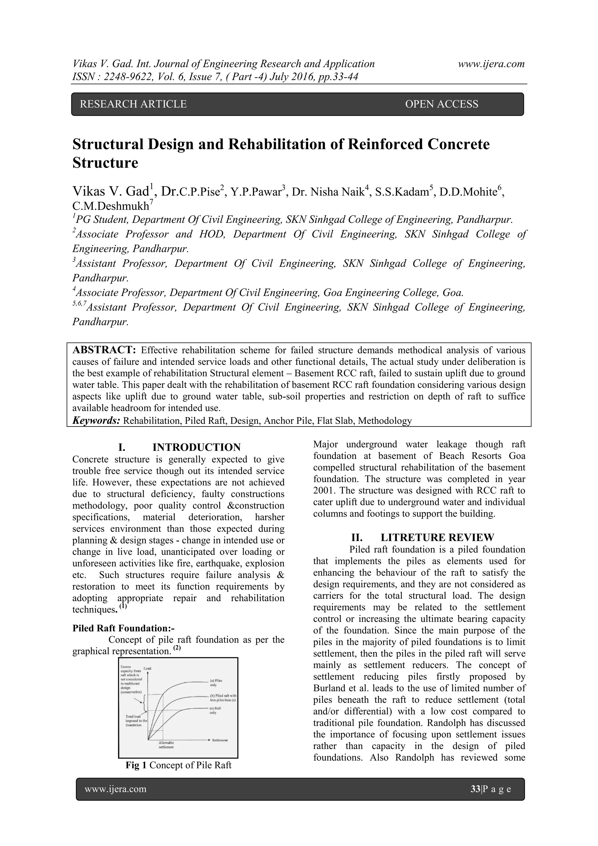
Concept of pile raft foundation as per the
graphical representation. (2)
Fig 1 Concept of Pile Raft
Major underground water leakage though raft
foundation at basement of Beach Resorts Goa
compelled structural rehabilitation of the basement
foundation. The structure was completed in year
2001. The structure was designed with RCC raft to
cater uplift due to underground water and individual
columns and footings to support the building.
II. LITRETURE REVIEW
Piled raft foundation is a piled foundation
that implements the piles as elements used for
enhancing the behaviour of the raft to satisfy the
design requirements, and they are not considered as
carriers for the total structural load. The design
requirements may be related to the settlement
control or increasing the ultimate bearing capacity
of the foundation. Since the main purpose of the
piles in the majority of piled foundations is to limit
settlement, then the piles in the piled raft will serve
mainly as settlement reducers. The concept of
settlement reducing piles firstly proposed by
Burland et al. leads to the use of limited number of
piles beneath the raft to reduce settlement (total
and/or differential) with a low cost compared to
traditional pile foundation. Randolph has discussed
the importance of focusing upon settlement issues
rather than capacity in the design of piled
foundations. Also Randolph has reviewed some
RESEARCH ARTICLE OPEN ACCESS
Vikas V. Gad. Int. Journal of Engineering Research and Application www.ijera.com
ISSN : 2248-9622, Vol. 6, Issue 7, ( Part -4) July 2016, pp.33-44
www.ijera.com 34|P a g e
analytical approaches for estimating the stiffness of
pile foundations systems. The piled raft foundation
has a complex behaviour involving different
interactions between its various components.
Therefore, a proper analytical model is needed to
evaluate these interactions. Numerical methods,
which are approximate, have been developed widely
in the last two decades because numerical methods
are less costly and may be used to consider many
kinds of different soil and foundation geometries
compared to field and model tests. According to
Poulo, there are three broad classes of numerical
analysis methods:
(1) simplified calculation methods
(2) Approximate computer-based methods and
(3) More rigorous computer-based methods.
Poulo also noted that the most feasible
method of analysis is the 3Dlinear/nonlinear finite
element or finite difference methods. Recently
nonlinear 3D finite element and finite difference
analyses have been conducted. However, modelling
problems related to the soil–structure interface still
remain in the 3D finite element and finite difference
analysis. The great challenge in the numerical
methods is the choice of proper input parameters to
give reasonable output results. The procedure of
choosing right values for the input parameters can
be adjusted by making back analysis for well
documented case histories.
Therefore, the overall objective of this
study focuses on investigating the behaviour of the
piled raft foundation system in clay by changing of
some parameters as: - Piles' number, length and
configuration (distribution of piles over the raft).
The change in the piles, number, length and
configuration in addition to the change in subsoil
properties produces a wide variety of cases to be
studied. From this variety we may see the effect of
changing each variable separately in a condition that
may be close to a real one. From the parametric
study aims at helping the engineers in taking a
logical path in an iterative design process for a piled
raft foundation. (3)
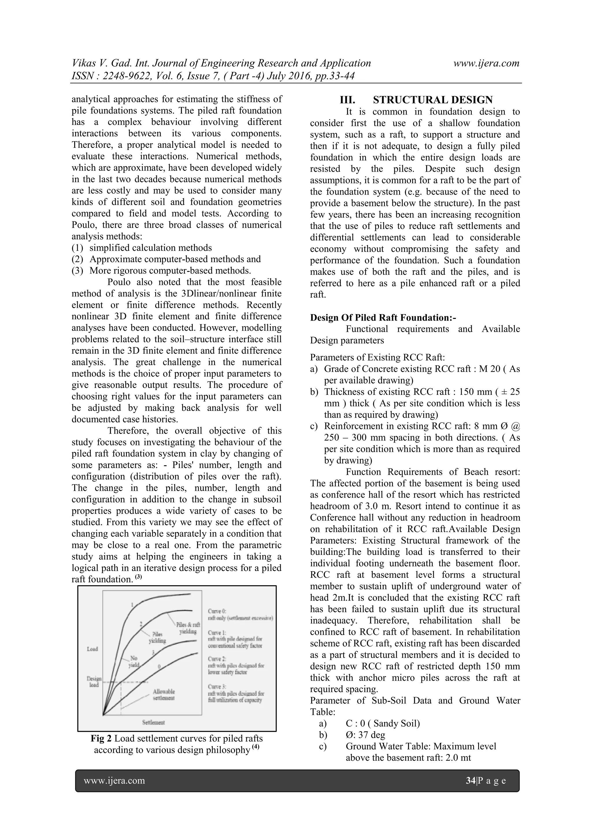
Fig 2 Load settlement curves for piled rafts
according to various design philosophy (4)
III. STRUCTURAL DESIGN
It is common in foundation design to
consider first the use of a shallow foundation
system, such as a raft, to support a structure and
then if it is not adequate, to design a fully piled
foundation in which the entire design loads are
resisted by the piles. Despite such design
assumptions, it is common for a raft to be the part of
the foundation system (e.g. because of the need to
provide a basement below the structure). In the past
few years, there has been an increasing recognition
that the use of piles to reduce raft settlements and
differential settlements can lead to considerable
economy without compromising the safety and
performance of the foundation. Such a foundation
makes use of both the raft and the piles, and is
referred to here as a pile enhanced raft or a piled
raft.
Design Of Piled Raft Foundation:-
Functional requirements and Available
Design parameters
Parameters of Existing RCC Raft:
a) Grade of Concrete existing RCC raft : M 20 ( As
per available drawing)
b) Thickness of existing RCC raft : 150 mm ( ± 25
mm ) thick ( As per site condition which is less
than as required by drawing)
c) Reinforcement in existing RCC raft: 8 mm Ø @
250 – 300 mm spacing in both directions. ( As
per site condition which is more than as required
by drawing)
Function Requirements of Beach resort:
The affected portion of the basement is being used
as conference hall of the resort which has restricted
headroom of 3.0 m. Resort intend to continue it as
Conference hall without any reduction in headroom
on rehabilitation of it RCC raft.Available Design
Parameters: Existing Structural framework of the
building:The building load is transferred to their
individual footing underneath the basement floor.
RCC raft at basement level forms a structural
member to sustain uplift of underground water of
head 2m.It is concluded that the existing RCC raft
has been failed to sustain uplift due its structural
inadequacy. Therefore, rehabilitation shall be
confined to RCC raft of basement. In rehabilitation
scheme of RCC raft, existing raft has been discarded
as a part of structural members and it is decided to
design new RCC raft of restricted depth 150 mm
thick with anchor micro piles across the raft at
required spacing.
Parameter of Sub-Soil Data and Ground Water
Table:
a) C : 0 ( Sandy Soil)
b) Ø: 37 deg
c) Ground Water Table: Maximum level
above the basement raft: 2.0 mt
Vikas V. Gad. Int. Journal of Engineering Research and Application www.ijera.com
ISSN : 2248-9622, Vol. 6, Issue 7, ( Part -4) July 2016, pp.33-44
www.ijera.com 35|P a g e
1. Design of Anchor Pile (A) (B)
:-
Piles in Granular Soils: -
The ultimate load capacity (Qu) of piles, in
kN, in granular soils is given by the following
formula from IS 2911:1:4:2010 or IRC 78:2000:-
n
Qu = Ap x (1/2 x D x γ x Nγ + PD x Nq) + ∑K x Pdi x tanδ x Asi
i=1
Part I Calculation. (End bearing resistance)
Ap x (1/2 x D x γ x Nγ + PD x Nq) --------------- (1)
Where,
Ap = C/s area of pile toe in cm2
= π/4 x 102
= 78.53 cm2
D = Stem diameter in cm
= 10 cm
γ = Effective unit weight of soil at toe Kg/cm3
= 0.001 Kg/cm3
Nγ = Bearing capacity factor as per IS: 6403 – 1981
Page no. 08
= 22.40
PD = Effective overburden pressure at pile toe
Kg/cm2
= 0.001 x (8.5) x 100
= 0.85 Kg/cm2
Nq = Bearing capacity factor as per IS: 6403-1981
= 18.40
Now Putting the values in the equation (1) we get:-
= 78.53 (½ x 10 x 0.001 x 22.40 + 0.85 x 18.40)
= 78.53 (0.112 + 15.64)
= 78.53 (15.752)
= 1237.00 Kg
= 1.237 T
Part II calculation (Skin friction resistance)
K x Pdi x tanδ x Asi---------------------- (2)
Where,
K = Co efficient of earth pressure = 1
Pdi = Effective overburden pressure in Kg/cm2
for
ith layer
= 0.001 x 8.5 x 100
= 0.85 Kg/cm2
δ = Angle of wall friction between piles and soil
= 37
Asi = Surface area of pile in cm2 in ith layer
= Perimeter x Height
= π x 10 x 850
= 26703.53 cm2
Now Putting the values in the equation (2) we get:-
= 1 x 0.85 x tan 37 x 26703.53
= 17104.17 Kg
= 17.104 T
Therefore Ultimate bearing capacity:-
Qu = 1.237 + 17.104
= 18.341 T
Safe bearing capacity:-
Taking factor of safety as 1.5:-
Q safe = 18.341/1.5
= 12.22 T
Taking factor of safety as 2.5:-
Q safe = 18.341/2.5
= 7.33 T
Calculation of number of piles required:-
For FS = 1.5
= Total load/Q safe
= 474.59/12.22
= 39 no’s
For FS = 2.5
= Total load/Q safe
= 474.59/7.33
= 65 no’s
Load on each pile:-
For FS = 1.5
= 474.59/39
= 12.16 T
For FS = 2.5
= 474.59/65
= 7.30 T
But for actual number of piles as per the site
condition is 95 no’s therefore,
= 474.59/95
= 4.99
= 5.0 T
Therefore the load on each pile is 5.0 T.
2. Design of Flat Slab for the new raft slab for
basement (5) (C)
:-
Flat slabs system of construction is one in
which the beams used in the conventional methods
of constructions are done away with. The slab
directly rests on the column and load from the slab
is directly transferred to the columns and then to the
foundation. To support heavy loads the thickness of
slab near the support with the column is increased
and these are called drops, or columns are generally
provided with enlarged heads called column heads
or capitals.
Absence of beam gives a plain ceiling, thus
giving better architectural appearance and also less
vulnerability in case of fire than in usual cases
where beams are used. Plain ceiling diffuses light
better, easier to construct and requires cheaper form
Vikas V. Gad. Int. Journal of Engineering Research and Application www.ijera.com
ISSN : 2248-9622, Vol. 6, Issue 7, ( Part -4) July 2016, pp.33-44
www.ijera.com 36|P a g e
work. As per local conditions and availability of
materials different countries have adopted different
methods for design of flat slabs and given their
guidelines in their respective codes.
The aim of this project is to try and
illustrate the methods used for flat slab design using
IS: 456-2000 design codes. For carrying out this
project an interior panel of a flat slab with
dimensions 1.0 x 1.0 m and was designed using the
codes given above.
Available data:-
1) Size of slab = 150 mm
2) Without drop and column head
3) Size of the column (anchor pile) = 100 mm Dia.
4) Grade of steel = Fe 415
5) Grade of concrete = M 25
1) Thickness:-
Since drop is not provided and HYSD bars are
used span to thickness ratioshall not be exceed
= Span/0.9 x 26
= 1000/28.8
= 34.72 mm
As per the IS 456-2000 the minimum thickness shall
be 125 mm, so we provided 150mm.
2) Load Calculation:-
Net upward pressure = 43.35 KN/m2
Therefore Factored load = 1.5 x 43.35
= 65.025 KN/m2
3) Total design load in a panel:-
W = 65.025 x L2 x Ln
Where,
L2 = Length of span transverse to L1
Ln = Clear span extending from face to face of
column, capitals, brackets or walls but not
less than 0.65 L1.
W = 65.025 x 1 x 0.824
W = 53.58 KN/m2
4) Moment:-
Panel moment (For interior panel)
M0 = WLn/8
= (53.58 x 0.824)/8
=5.51KN-m
Panel –ve moment (For interior panel)
= 0.65 x M0
= 0.65 x 5.51
= 3.58 KN-m
Panel +ve Moment (For interior panel)
= 0.35 x M0
= 0.35 x 5.51
= 1.93 KN-m
Distribution of moment into column strip and
middle strip:-
Column strip in
KN-m
Middle strip in
KN-m
-ve moment Mnc = 5.38 Mnm = 1.78
+ve moment Mpc = 2.32 Mpm = 1.55
5) Checking for the thickness selected:-
Since Fe 415 steel is used
Mulim = 0.138 fck bd2
Width of column strip = 0.50 x 1000
= 500 mm
Mu lim = 0.138 x 25 x 500 x 1502
= 38.81 x 10⁶
N-mm
= 38.81 KN-m
Thickness provided is OK.
6) Check for shear:-
Shear to be resisted by critical section
V = 53.58 x 1 x 1 – 53.58 x 0.212 x 0.212
V = 53.58 – 2.408
V = 51.172 KN
δv = (V x 1000)/4 x 212 x 124
= (51.172 x 1000)/ 4 x 212 x 124
= 0.48 N/mm2
Ks = 0.5 + βc
Where,
βc = 1
But Ks value should not be greater than 1
Therefore Ks = 1
And,
δc = 0.25 √ fck
= 0.25 √ 25
= 1.25 N/mm2
Therefore δv <δc ------------------------------Safe
Shear reinforcement not required.
7) Reinforcement:-
a) For –ve moment in the column strip.
Mnc= 5.38 KN-m
Mnc= 0.87 x fy x Ast x d (1 – (Ast/bd) x
(fy/fck))
5.38 x 106
= 0.87 x 415 x Ast x 124 (1 –
(Ast/500 x 124) x (415/25))
5.38 x 106
= 44.77 x 10³
Ast (1 – 1.33 x 10⁻⁴
)
5.38 x 106
= 44.77 x 10³
Ast – 5.95Ast2
5.95 Ast2
– 44.77 x 10³
Ast + 5.38 x 106
= 0
Therefore,
Ast = 122.15 mm2
Vikas V. Gad. Int. Journal of Engineering Research and Application www.ijera.com
ISSN : 2248-9622, Vol. 6, Issue 7, ( Part -4) July 2016, pp.33-44
www.ijera.com 37|P a g e
This is to be provided in a column strip of width
1000 mm. Hence using 12 mm bars spacing required
is given by,
S = ((π/4 x 122)/122.15) x 1000
S = 925 mm
b) For +ve moment in the column strip.
Mpc= 2.32 KN-m
Mpc= 0.87 x fy x Ast x d (1 – (Ast/bd) x
(fy/fck))
2.32 x 106
= 0.87 x 415 x Ast x 124 (1 –
(Ast/500 x 124) x (415/25))
2.32 x 106
= 44.77 x 10³
Ast (1 – 1.33 x 10⁻⁴
)
2.32 x 106
= 44.77 x 10³
Ast – 5.95Ast2
5.95 Ast2
– 44.77 x 10³
Ast + 2.32 x 106
= 0
Therefore,
Ast = 52.182 mm2
This is to be provided in a column strip of width
1000 mm. Hence using 12 mm bars spacing
required is given by,
S = ((π/4 x 122)/52.182) x 1000
S = 2167 mm
c) For –ve moment in the middle strip.
Mnm= 1.78KN-m
Mnm= 0.87 x fy x Ast x d (1 – (Ast/bd) x
(fy/fck))
1.78 x 106
= 0.87 x 415 x Ast x 124 (1 –
(Ast/500 x 124) x (415/25))
1.78 x 106
= 44.77 x 10³
Ast (1 – 1.33 x 10⁻⁴
)
1.78 x 106
= 44.77 x 10³
Ast – 5.95Ast2
5.95 Ast2
– 44.77 x 10³
Ast + 1.78 x 106
= 0
Therefore,
Ast = 39.97 mm2
This is to be provided in a middle strip of width
1000 mm. Hence using 12 mm bars spacing
required is given by,
S = ((π/4 x 122)/39.97) x 1000
S = 2829 mm
d) For +ve moment in the middle strip.
Mpm = 1.55 KN-m
Mpm= 0.87 x fy x Ast x d (1 – (Ast/bd) x
(fy/fck))
1.55 x 106
= 0.87 x 415 x Ast x 124 (1 –
(Ast/500 x 124) x (415/25))
1.55 x 106
= 44.77 x 10³
Ast (1 – 1.33 x 10⁻⁴
)
1.55 x 106
= 44.77 x 10³
Ast – 5.95Ast2
5.95 Ast2
– 44.77 x 10³
Ast + 1.55 x 106
= 0
Therefore,
Ast = 34.782 mm2
This is to be provided in a middle strip of width
1000 mm. Hence using 12 mm bars spacing
required is given by,
S = ((π/4 x 122)/34.782) x 1000
= 3251 mm
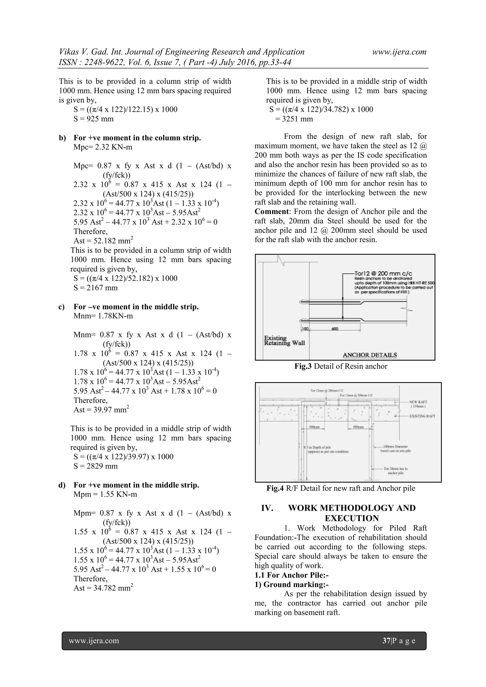
From the design of new raft slab, for
maximum moment, we have taken the steel as 12 @
200 mm both ways as per the IS code specification
and also the anchor resin has been provided so as to
minimize the chances of failure of new raft slab, the
minimum depth of 100 mm for anchor resin has to
be provided for the interlocking between the new
raft slab and the retaining wall.
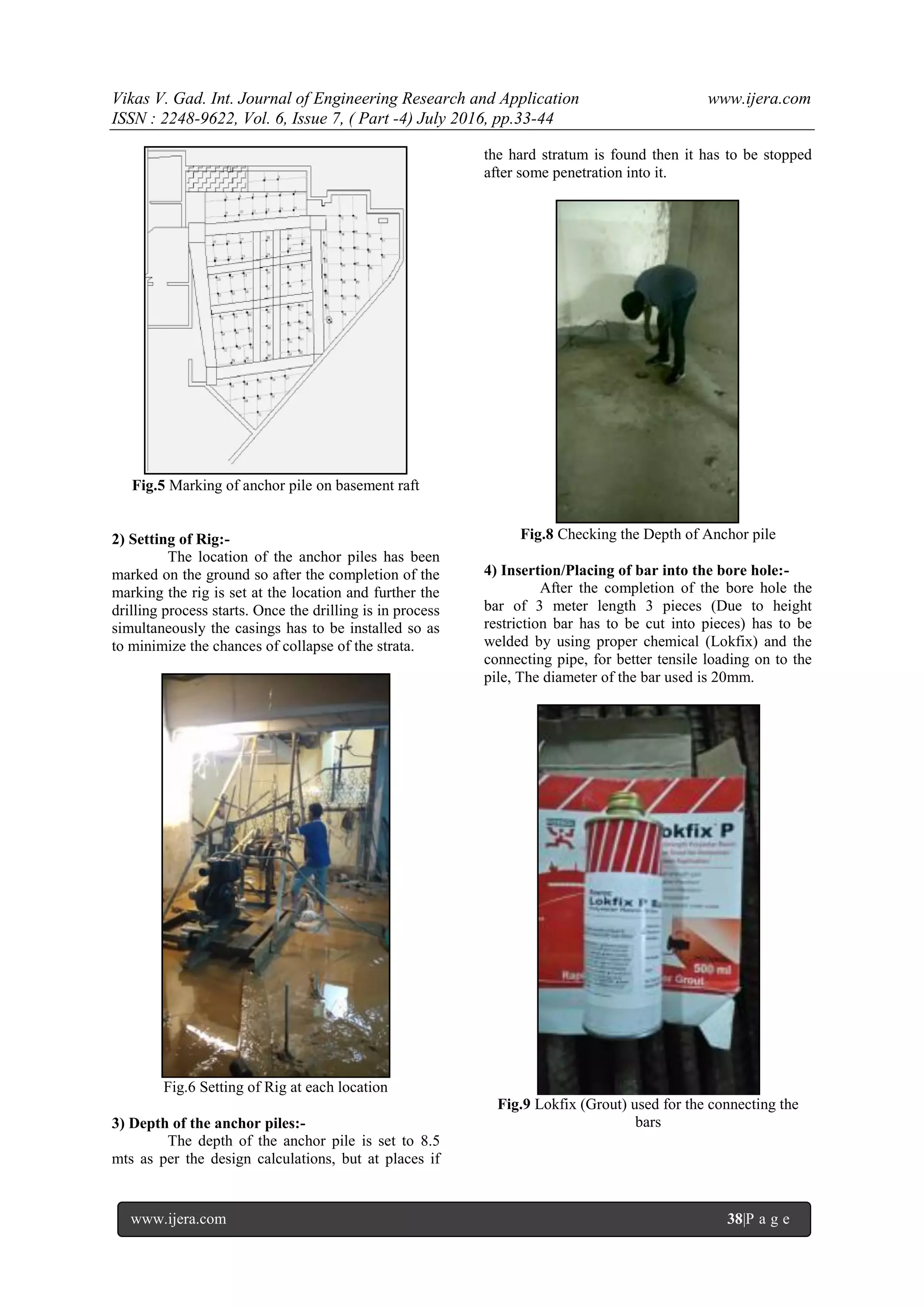
Comment: From the design of Anchor pile and the
raft slab, 20mm dia Steel should be used for the
anchor pile and 12 @ 200mm steel should be used
for the raft slab with the anchor resin.
Fig.3 Detail of Resin anchor
Fig.4 R/F Detail for new raft and Anchor pile
IV. WORK METHODOLOGY AND
EXECUTION
1. Work Methodology for Piled Raft
Foundation:-The execution of rehabilitation should
be carried out according to the following steps.
Special care should always be taken to ensure the
high quality of work.
1.1 For Anchor Pile:-
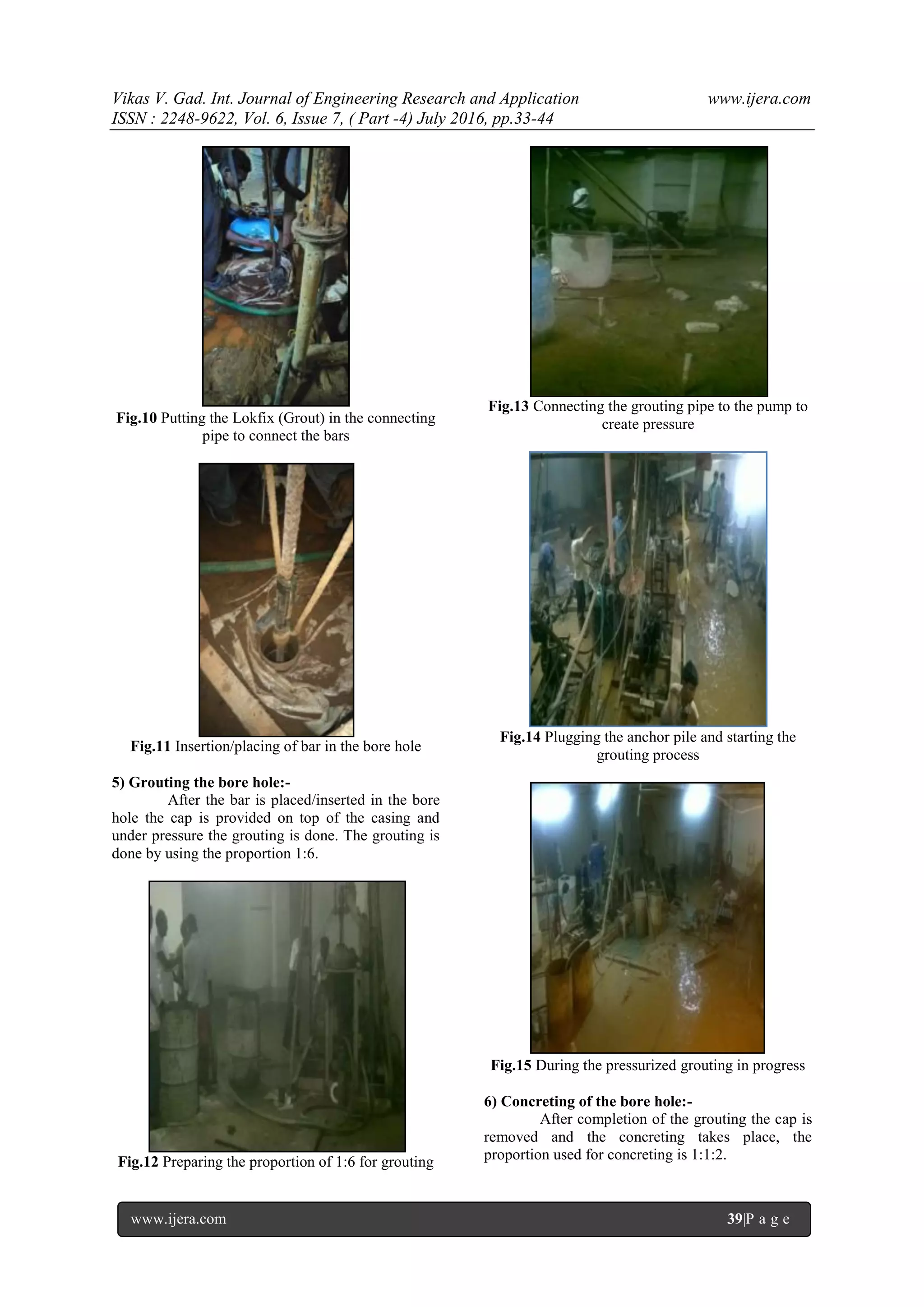
1) Ground marking:-
As per the rehabilitation design issued by
me, the contractor has carried out anchor pile
marking on basement raft.
Vikas V. Gad. Int. Journal of Engineering Research and Application www.ijera.com
ISSN : 2248-9622, Vol. 6, Issue 7, ( Part -4) July 2016, pp.33-44
www.ijera.com 38|P a g e
Fig.5 Marking of anchor pile on basement raft
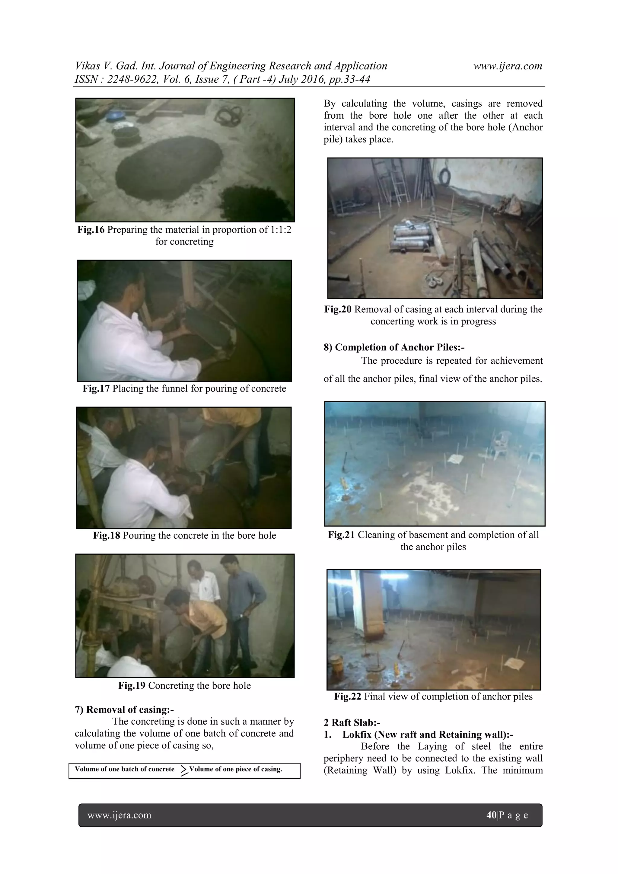
2) Setting of Rig:-
The location of the anchor piles has been
marked on the ground so after the completion of the
marking the rig is set at the location and further the
drilling process starts. Once the drilling is in process
simultaneously the casings has to be installed so as
to minimize the chances of collapse of the strata.
Fig.6 Setting of Rig at each location
3) Depth of the anchor piles:-
The depth of the anchor pile is set to 8.5
mts as per the design calculations, but at places if
the hard stratum is found then it has to be stopped
after some penetration into it.
Fig.8 Checking the Depth of Anchor pile
4) Insertion/Placing of bar into the bore hole:-
After the completion of the bore hole the
bar of 3 meter length 3 pieces (Due to height
restriction bar has to be cut into pieces) has to be
welded by using proper chemical (Lokfix) and the
connecting pipe, for better tensile loading on to the
pile, The diameter of the bar used is 20mm.
Fig.9 Lokfix (Grout) used for the connecting the
bars
Vikas V. Gad. Int. Journal of Engineering Research and Application www.ijera.com
ISSN : 2248-9622, Vol. 6, Issue 7, ( Part -4) July 2016, pp.33-44
www.ijera.com 39|P a g e
Fig.10 Putting the Lokfix (Grout) in the connecting
pipe to connect the bars
Fig.11 Insertion/placing of bar in the bore hole
5) Grouting the bore hole:-
After the bar is placed/inserted in the bore
hole the cap is provided on top of the casing and
under pressure the grouting is done. The grouting is
done by using the proportion 1:6.
Fig.12 Preparing the proportion of 1:6 for grouting
Fig.13 Connecting the grouting pipe to the pump to
create pressure
Fig.14 Plugging the anchor pile and starting the
grouting process
Fig.15 During the pressurized grouting in progress
6) Concreting of the bore hole:-
After completion of the grouting the cap is
removed and the concreting takes place, the
proportion used for concreting is 1:1:2.
Vikas V. Gad. Int. Journal of Engineering Research and Application www.ijera.com
ISSN : 2248-9622, Vol. 6, Issue 7, ( Part -4) July 2016, pp.33-44
www.ijera.com 40|P a g e
Fig.16 Preparing the material in proportion of 1:1:2
for concreting
Fig.17 Placing the funnel for pouring of concrete
Fig.18 Pouring the concrete in the bore hole
Fig.19 Concreting the bore hole
7) Removal of casing:-
The concreting is done in such a manner by
calculating the volume of one batch of concrete and
volume of one piece of casing so,
Volume of one batch of concrete Volume of one piece of casing.
By calculating the volume, casings are removed
from the bore hole one after the other at each
interval and the concreting of the bore hole (Anchor
pile) takes place.
Fig.20 Removal of casing at each interval during the
concerting work is in progress
8) Completion of Anchor Piles:-
The procedure is repeated for achievement
of all the anchor piles, final view of the anchor piles.
Fig.21 Cleaning of basement and completion of all
the anchor piles
Fig.22 Final view of completion of anchor piles
2 Raft Slab:-
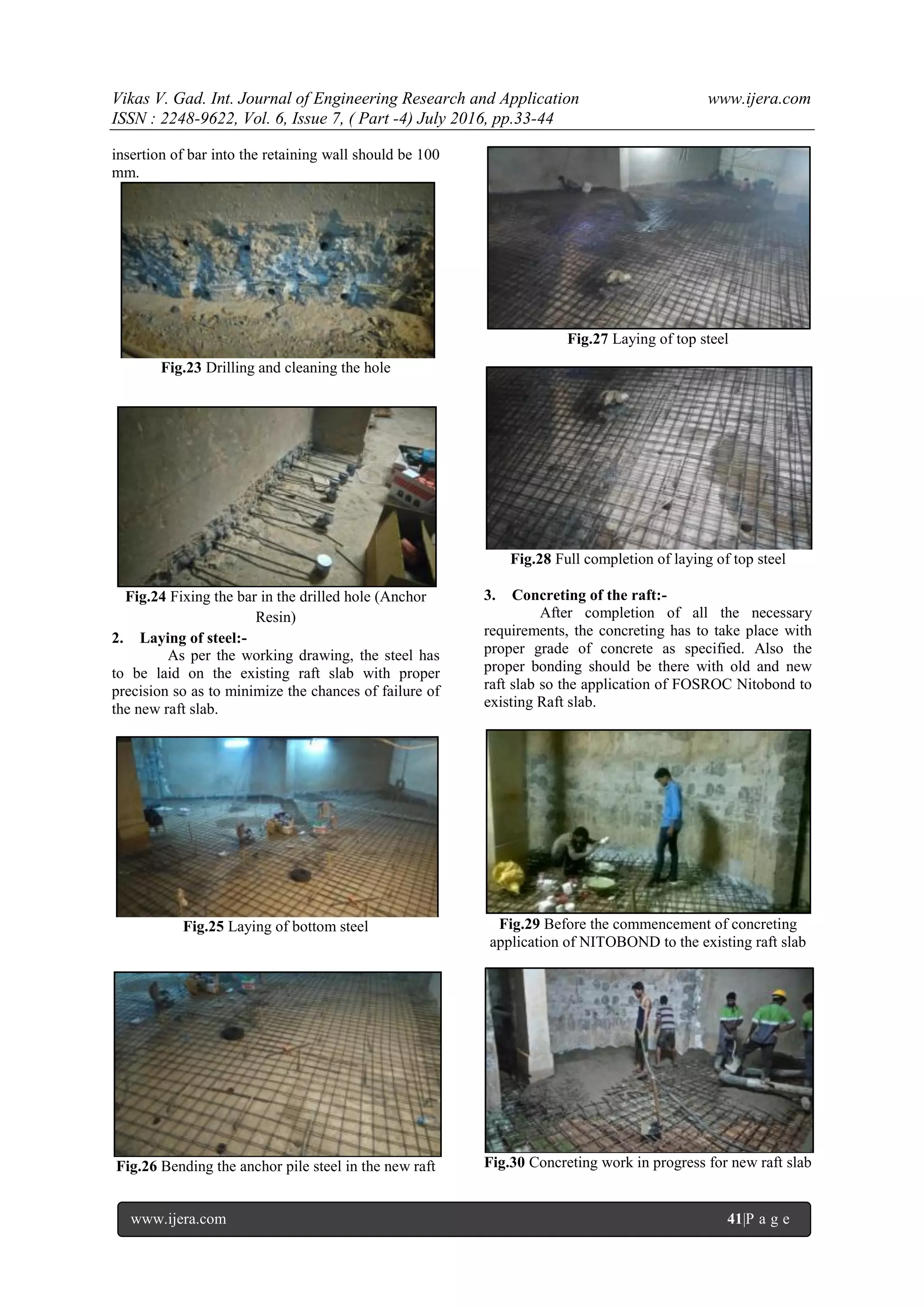
1. Lokfix (New raft and Retaining wall):-
Before the Laying of steel the entire
periphery need to be connected to the existing wall
(Retaining Wall) by using Lokfix. The minimum
Vikas V. Gad. Int. Journal of Engineering Research and Application www.ijera.com
ISSN : 2248-9622, Vol. 6, Issue 7, ( Part -4) July 2016, pp.33-44
www.ijera.com 41|P a g e
insertion of bar into the retaining wall should be 100
mm.
Fig.23 Drilling and cleaning the hole
Fig.24 Fixing the bar in the drilled hole (Anchor
Resin)
2. Laying of steel:-
As per the working drawing, the steel has
to be laid on the existing raft slab with proper
precision so as to minimize the chances of failure of
the new raft slab.
Fig.25 Laying of bottom steel
Fig.26 Bending the anchor pile steel in the new raft
Fig.27 Laying of top steel
Fig.28 Full completion of laying of top steel
3. Concreting of the raft:-
After completion of all the necessary
requirements, the concreting has to take place with
proper grade of concrete as specified. Also the
proper bonding should be there with old and new
raft slab so the application of FOSROC Nitobond to
existing Raft slab.
Fig.29 Before the commencement of concreting
application of NITOBOND to the existing raft slab
Fig.30 Concreting work in progress for new raft slab
Vikas V. Gad. Int. Journal of Engineering Research and Application www.ijera.com
ISSN : 2248-9622, Vol. 6, Issue 7, ( Part -4) July 2016, pp.33-44
www.ijera.com 42|P a g e
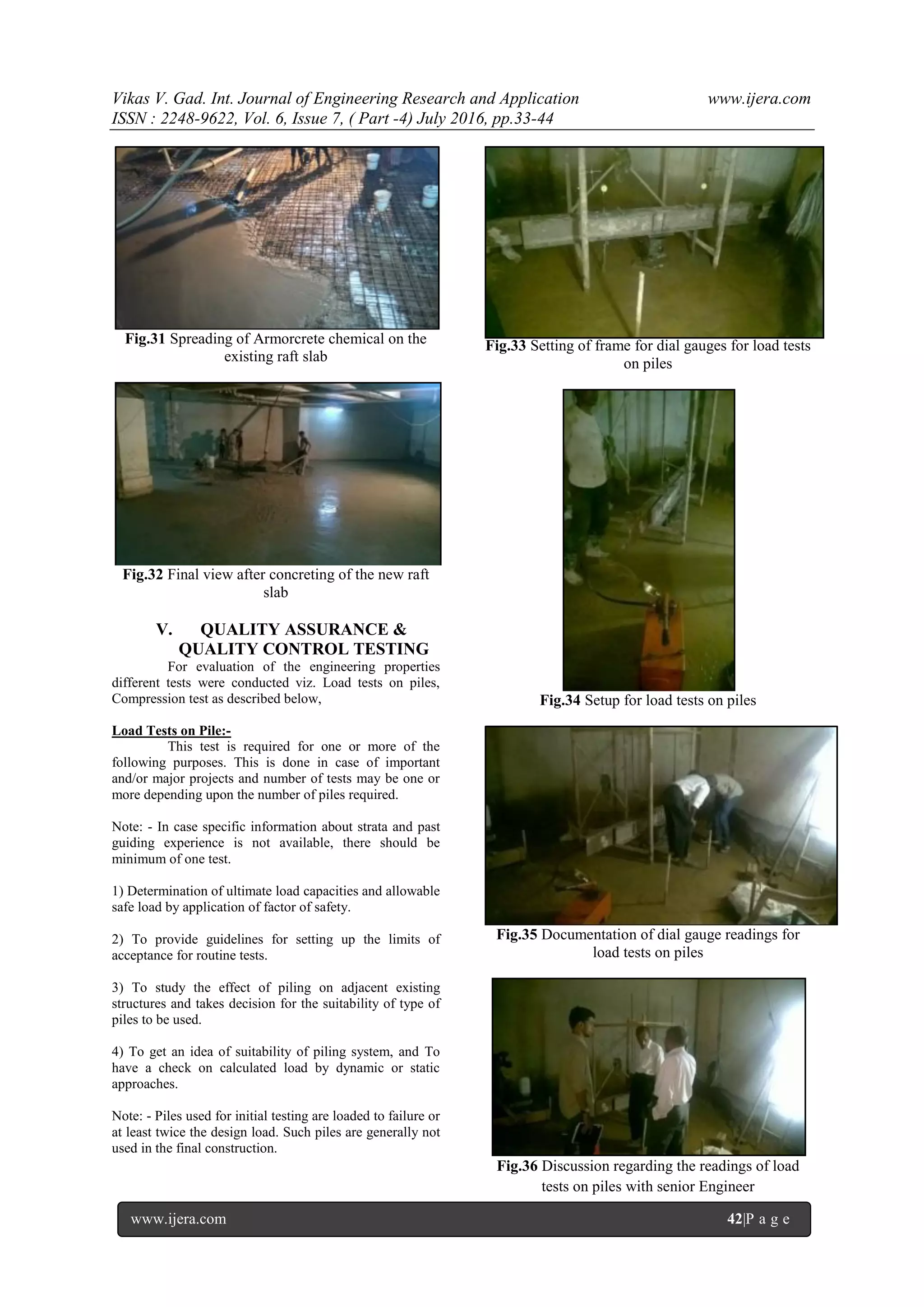
Fig.31 Spreading of Armorcrete chemical on the
existing raft slab
Fig.32 Final view after concreting of the new raft
slab
V. QUALITY ASSURANCE &
QUALITY CONTROL TESTING
For evaluation of the engineering properties
different tests were conducted viz. Load tests on piles,
Compression test as described below,
Load Tests on Pile:-
This test is required for one or more of the
following purposes. This is done in case of important
and/or major projects and number of tests may be one or
more depending upon the number of piles required.
Note: - In case specific information about strata and past
guiding experience is not available, there should be
minimum of one test.
1) Determination of ultimate load capacities and allowable
safe load by application of factor of safety.
2) To provide guidelines for setting up the limits of
acceptance for routine tests.
3) To study the effect of piling on adjacent existing
structures and takes decision for the suitability of type of
piles to be used.
4) To get an idea of suitability of piling system, and To
have a check on calculated load by dynamic or static
approaches.
Note: - Piles used for initial testing are loaded to failure or
at least twice the design load. Such piles are generally not
used in the final construction.
Fig.33 Setting of frame for dial gauges for load tests
on piles
Fig.34 Setup for load tests on piles
Fig.35 Documentation of dial gauge readings for
load tests on piles
Fig.36 Discussion regarding the readings of load
tests on piles with senior Engineer
Vikas V. Gad. Int. Journal of Engineering Research and Application www.ijera.com
ISSN : 2248-9622, Vol. 6, Issue 7, ( Part -4) July 2016, pp.33-44
www.ijera.com 43|P a g e
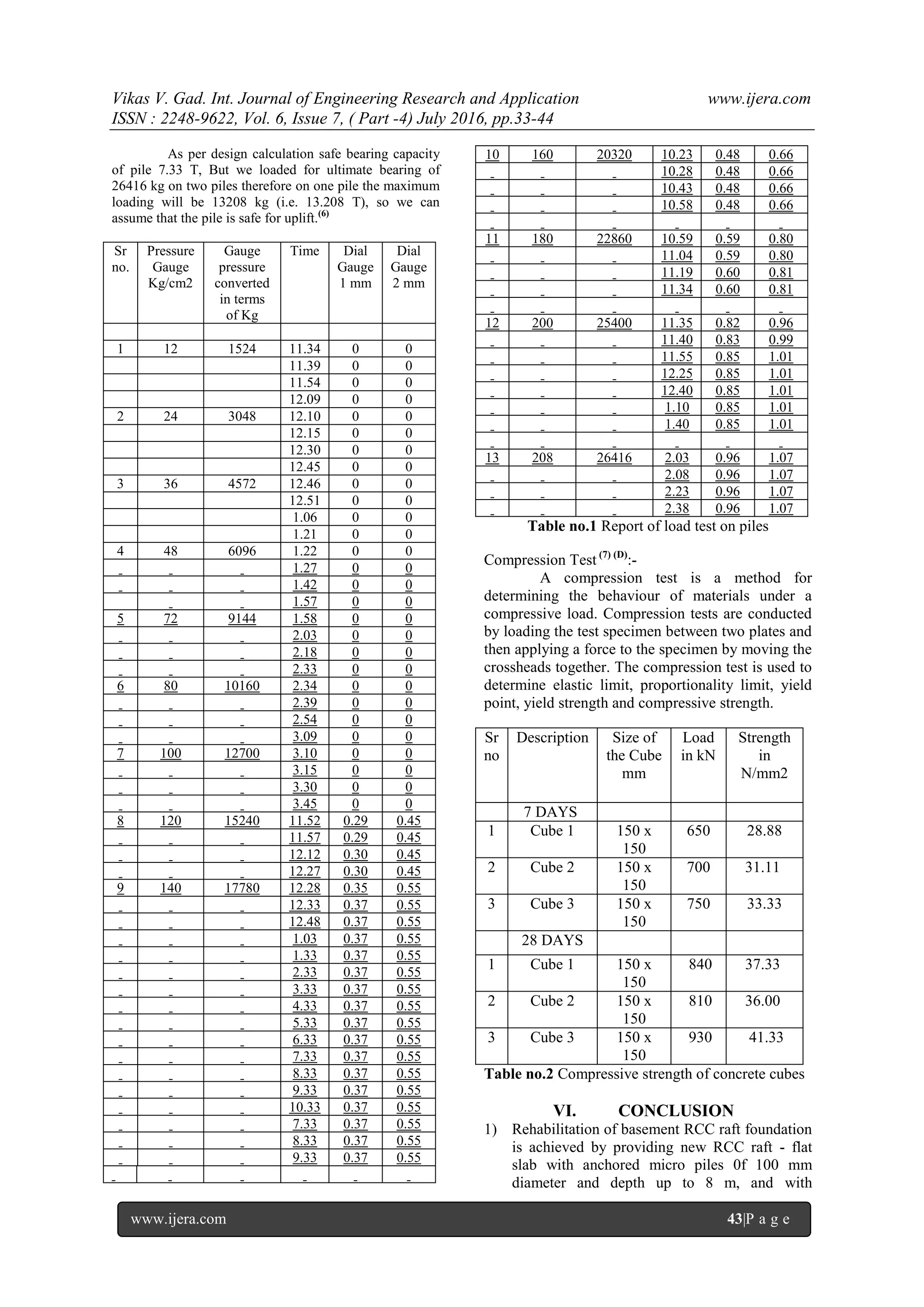
As per design calculation safe bearing capacity
of pile 7.33 T, But we loaded for ultimate bearing of
26416 kg on two piles therefore on one pile the maximum
loading will be 13208 kg (i.e. 13.208 T), so we can
assume that the pile is safe for uplift.(6)
Sr
no.
Pressure
Gauge
Kg/cm2
Gauge
pressure
converted
in terms
of Kg
Time Dial
Gauge
1 mm
Dial
Gauge
2 mm
1 12 1524 11.34 0 0
11.39 0 0
11.54 0 0
12.09 0 0
2 24 3048 12.10 0 0
12.15 0 0
12.30 0 0
12.45 0 0
3 36 4572 12.46 0 0
12.51 0 0
1.06 0 0
1.21 0 0
4 48 6096 1.22 0 0
1.27 0 0
1.42 0 0
1.57 0 0
5 72 9144 1.58 0 0
2.03 0 0
2.18 0 0
2.33 0 0
6 80 10160 2.34 0 0
2.39 0 0
2.54 0 0
3.09 0 0
7 100 12700 3.10 0 0
3.15 0 0
3.30 0 0
3.45 0 0
8 120 15240 11.52 0.29 0.45
11.57 0.29 0.45
12.12 0.30 0.45
12.27 0.30 0.45
9 140 17780 12.28 0.35 0.55
12.33 0.37 0.55
12.48 0.37 0.55
1.03 0.37 0.55
1.33 0.37 0.55
2.33 0.37 0.55
3.33 0.37 0.55
4.33 0.37 0.55
5.33 0.37 0.55
6.33 0.37 0.55
7.33 0.37 0.55
8.33 0.37 0.55
9.33 0.37 0.55
10.33 0.37 0.55
7.33 0.37 0.55
8.33 0.37 0.55
9.33 0.37 0.55
10 160 20320 10.23 0.48 0.66
10.28 0.48 0.66
10.43 0.48 0.66
10.58 0.48 0.66
11 180 22860 10.59 0.59 0.80
11.04 0.59 0.80
11.19 0.60 0.81
11.34 0.60 0.81
12 200 25400 11.35 0.82 0.96
11.40 0.83 0.99
11.55 0.85 1.01
12.25 0.85 1.01
12.40 0.85 1.01
1.10 0.85 1.01
1.40 0.85 1.01
13 208 26416 2.03 0.96 1.07
2.08 0.96 1.07
2.23 0.96 1.07
2.38 0.96 1.07
Table no.1 Report of load test on piles
Compression Test (7) (D)
:-
A compression test is a method for
determining the behaviour of materials under a
compressive load. Compression tests are conducted
by loading the test specimen between two plates and
then applying a force to the specimen by moving the
crossheads together. The compression test is used to
determine elastic limit, proportionality limit, yield
point, yield strength and compressive strength.
Sr
no
Description Size of
the Cube
mm
Load
in kN
Strength
in
N/mm2
7 DAYS
1 Cube 1 150 x
150
650 28.88
2 Cube 2 150 x
150
700 31.11
3 Cube 3 150 x
150
750 33.33
28 DAYS
1 Cube 1 150 x
150
840 37.33
2 Cube 2 150 x
150
810 36.00
3 Cube 3 150 x
150
930 41.33
Table no.2 Compressive strength of concrete cubes
VI. CONCLUSION
1) Rehabilitation of basement RCC raft foundation
is achieved by providing new RCC raft - flat
slab with anchored micro piles 0f 100 mm
diameter and depth up to 8 m, and with
Vikas V. Gad. Int. Journal of Engineering Research and Application www.ijera.com
ISSN : 2248-9622, Vol. 6, Issue 7, ( Part -4) July 2016, pp.33-44
www.ijera.com 44|P a g e
injection grouting of sandy strata underlying the
raft foundation.
2) Restriction on depth of the basement RCC raft
was also taken into account and thereby no
reduction in headroom for intended use, as
available earlier
3) Methodical analysis of various causes of
structural failure, effective and timely
rehabilitation can restore the structure to
intended use.
REFERENCES
[1]. D.Monica, B. Lavanya, strengthening of
damaged structures, International Journal
of Civil Engineering and Technology 2015,
pp. 92-99
[2]. Y.C. Tan, C.M.Chow, Design of piled raft
foundation on soft ground, GNPGEO 2004,
pp. 1-20
[3]. Adel Y. Akl, Mohamed H. Mansour and
Heba K. Moustafa, Effect of changing
configurations and lengths of piles on piled
raft foundation behaviour, Civil
Engineering and Urban Planning: An
International Journal 2014, pp. 49-65
[4]. Simeneh Abate, Report on Analysis and
parametric study of piled raft foundation
using finite element based software, Addis
Ababa university, pp. 1-85
[5]. M.Anitha, B.Q.Rahman, JJ .Vijay,
Analysis and Design of Flat Slabs Using
Various Codes, Indian Institute of
Information Technology 2007, pp. 1-53
[6]. Ascalew Abebe & Dr Ian GN Smith. A
student guide (http://www.tumcivil.com)
[7]. Peter Claisse & Christopher Dean.
Compressive strength of concrete after
early loading. Institute of Civil Engineers
2012, pp. 1-6
CODES
(A) IS 2911:1:4:2010 - Code Of Practice for Design and
Construction of Pile Foundations: Part 1 Concrete
Piles, Section 4 Bored Precast Concrete Piles.
(B) IRC 78:2000 - Standard Specifications and Code of
Practices for Road Bridges.
(C) IS 456: 2000 – Plain and Reinforced Concrete Code
of Practice
(D) IS 516:1959 – Method of tests for strength of
concrete

More Related Content

What's hot

Seismic Analysis for Safety of Dams
Seismic Analysis for Safety of DamsSeismic Analysis for Safety of Dams
Seismic Analysis for Safety of DamsIOSR Journals
 
Design of flexible pavement
Design of flexible pavementDesign of flexible pavement
Design of flexible pavementBhavik A Shah
 
Analysis of Unsymmetrical Building Resting on Sloping Ground by Dividing in 2...
Analysis of Unsymmetrical Building Resting on Sloping Ground by Dividing in 2...Analysis of Unsymmetrical Building Resting on Sloping Ground by Dividing in 2...
Analysis of Unsymmetrical Building Resting on Sloping Ground by Dividing in 2...IRJET Journal
 
Pavement thickness design
Pavement thickness designPavement thickness design
Pavement thickness designSohail Khan
 
"The Load Capacity of Driven Cast-In-Situ Piles Derived from Installation Par...
"The Load Capacity of Driven Cast-In-Situ Piles Derived from Installation Par..."The Load Capacity of Driven Cast-In-Situ Piles Derived from Installation Par...
"The Load Capacity of Driven Cast-In-Situ Piles Derived from Installation Par...Remedy Geotechnics Ltd
 
Heavy Duty Pavement Design
Heavy Duty Pavement DesignHeavy Duty Pavement Design
Heavy Duty Pavement Designguestdbd9fccc
 
DYNAMIC RESPONSE OF CONCRETE GRAVITY DAM ON RANDOM SOIL
  DYNAMIC RESPONSE OF CONCRETE GRAVITY DAM ON RANDOM SOIL  DYNAMIC RESPONSE OF CONCRETE GRAVITY DAM ON RANDOM SOIL
DYNAMIC RESPONSE OF CONCRETE GRAVITY DAM ON RANDOM SOILIAEME Publication
 
IRJET- Numerical Analysis of L-Shaped Retaining Wall with Compressible Expand...
IRJET- Numerical Analysis of L-Shaped Retaining Wall with Compressible Expand...IRJET- Numerical Analysis of L-Shaped Retaining Wall with Compressible Expand...
IRJET- Numerical Analysis of L-Shaped Retaining Wall with Compressible Expand...IRJET Journal
 
Determining equivalent single wheel load.(ESWL)
Determining equivalent single wheel load.(ESWL) Determining equivalent single wheel load.(ESWL)
Determining equivalent single wheel load.(ESWL) Imran Nawaz
 
Lect 6 pavement design
Lect 6 pavement designLect 6 pavement design
Lect 6 pavement designM Firdaus
 
Experimental behaviour and analysis of stress in rigid pavement
Experimental behaviour and analysis of stress in rigid pavementExperimental behaviour and analysis of stress in rigid pavement
Experimental behaviour and analysis of stress in rigid pavementVivek Loyola
 
DESIGN OF RIGID PAVEMENT AND ITS COST-BENEFIT ANALYSIS BY USAGE OF VITRIFIED ...
DESIGN OF RIGID PAVEMENT AND ITS COST-BENEFIT ANALYSIS BY USAGE OF VITRIFIED ...DESIGN OF RIGID PAVEMENT AND ITS COST-BENEFIT ANALYSIS BY USAGE OF VITRIFIED ...
DESIGN OF RIGID PAVEMENT AND ITS COST-BENEFIT ANALYSIS BY USAGE OF VITRIFIED ...IAEME Publication
 
Pavement materials and design in western australia by geoffrey cocks
Pavement materials and design in western australia by geoffrey cocksPavement materials and design in western australia by geoffrey cocks
Pavement materials and design in western australia by geoffrey cocksEngineers Australia
 
pavement analysis
pavement analysis pavement analysis
pavement analysis Saeed Badeli
 
Analytical study on soil pile interaction effect in the variation of natural ...
Analytical study on soil pile interaction effect in the variation of natural ...Analytical study on soil pile interaction effect in the variation of natural ...
Analytical study on soil pile interaction effect in the variation of natural ...IAEME Publication
 
Seismic Analysis of Reinforced Concrete Shaft Support Water Storage Tank
Seismic Analysis of Reinforced Concrete Shaft Support Water Storage TankSeismic Analysis of Reinforced Concrete Shaft Support Water Storage Tank
Seismic Analysis of Reinforced Concrete Shaft Support Water Storage TankIJERA Editor
 
Rehabilitation of low volume flexible pavements by white topping a case study
Rehabilitation of low volume flexible pavements by white topping a case studyRehabilitation of low volume flexible pavements by white topping a case study
Rehabilitation of low volume flexible pavements by white topping a case studyeSAT Publishing House
 

What's hot (19)

Seismic Analysis for Safety of Dams
Seismic Analysis for Safety of DamsSeismic Analysis for Safety of Dams
Seismic Analysis for Safety of Dams
 
Design of flexible pavement
Design of flexible pavementDesign of flexible pavement
Design of flexible pavement
 
Analysis of Unsymmetrical Building Resting on Sloping Ground by Dividing in 2...
Analysis of Unsymmetrical Building Resting on Sloping Ground by Dividing in 2...Analysis of Unsymmetrical Building Resting on Sloping Ground by Dividing in 2...
Analysis of Unsymmetrical Building Resting on Sloping Ground by Dividing in 2...
 
Pavement thickness design
Pavement thickness designPavement thickness design
Pavement thickness design
 
"The Load Capacity of Driven Cast-In-Situ Piles Derived from Installation Par...
"The Load Capacity of Driven Cast-In-Situ Piles Derived from Installation Par..."The Load Capacity of Driven Cast-In-Situ Piles Derived from Installation Par...
"The Load Capacity of Driven Cast-In-Situ Piles Derived from Installation Par...
 
Heavy Duty Pavement Design
Heavy Duty Pavement DesignHeavy Duty Pavement Design
Heavy Duty Pavement Design
 
S7
S7S7
S7
 
DYNAMIC RESPONSE OF CONCRETE GRAVITY DAM ON RANDOM SOIL
  DYNAMIC RESPONSE OF CONCRETE GRAVITY DAM ON RANDOM SOIL  DYNAMIC RESPONSE OF CONCRETE GRAVITY DAM ON RANDOM SOIL
DYNAMIC RESPONSE OF CONCRETE GRAVITY DAM ON RANDOM SOIL
 
IRJET- Numerical Analysis of L-Shaped Retaining Wall with Compressible Expand...
IRJET- Numerical Analysis of L-Shaped Retaining Wall with Compressible Expand...IRJET- Numerical Analysis of L-Shaped Retaining Wall with Compressible Expand...
IRJET- Numerical Analysis of L-Shaped Retaining Wall with Compressible Expand...
 
Determining equivalent single wheel load.(ESWL)
Determining equivalent single wheel load.(ESWL) Determining equivalent single wheel load.(ESWL)
Determining equivalent single wheel load.(ESWL)
 
Flexible Pavement Design
Flexible Pavement DesignFlexible Pavement Design
Flexible Pavement Design
 
Lect 6 pavement design
Lect 6 pavement designLect 6 pavement design
Lect 6 pavement design
 
Experimental behaviour and analysis of stress in rigid pavement
Experimental behaviour and analysis of stress in rigid pavementExperimental behaviour and analysis of stress in rigid pavement
Experimental behaviour and analysis of stress in rigid pavement
 
DESIGN OF RIGID PAVEMENT AND ITS COST-BENEFIT ANALYSIS BY USAGE OF VITRIFIED ...
DESIGN OF RIGID PAVEMENT AND ITS COST-BENEFIT ANALYSIS BY USAGE OF VITRIFIED ...DESIGN OF RIGID PAVEMENT AND ITS COST-BENEFIT ANALYSIS BY USAGE OF VITRIFIED ...
DESIGN OF RIGID PAVEMENT AND ITS COST-BENEFIT ANALYSIS BY USAGE OF VITRIFIED ...
 
Pavement materials and design in western australia by geoffrey cocks
Pavement materials and design in western australia by geoffrey cocksPavement materials and design in western australia by geoffrey cocks
Pavement materials and design in western australia by geoffrey cocks
 
pavement analysis
pavement analysis pavement analysis
pavement analysis
 
Analytical study on soil pile interaction effect in the variation of natural ...
Analytical study on soil pile interaction effect in the variation of natural ...Analytical study on soil pile interaction effect in the variation of natural ...
Analytical study on soil pile interaction effect in the variation of natural ...
 
Seismic Analysis of Reinforced Concrete Shaft Support Water Storage Tank
Seismic Analysis of Reinforced Concrete Shaft Support Water Storage TankSeismic Analysis of Reinforced Concrete Shaft Support Water Storage Tank
Seismic Analysis of Reinforced Concrete Shaft Support Water Storage Tank
 
Rehabilitation of low volume flexible pavements by white topping a case study
Rehabilitation of low volume flexible pavements by white topping a case studyRehabilitation of low volume flexible pavements by white topping a case study
Rehabilitation of low volume flexible pavements by white topping a case study
 

Similar to Structural Design and Rehabilitation of Reinforced Concrete Structure

IRJET- Design of Box Culvert using Visual Basic
IRJET- Design of Box Culvert using Visual BasicIRJET- Design of Box Culvert using Visual Basic
IRJET- Design of Box Culvert using Visual BasicIRJET Journal
 
SEISMIC RESISTIVITY AND RETROFITTING OF RC FRAME BUILDING
SEISMIC RESISTIVITY AND RETROFITTING OF RC FRAME BUILDINGSEISMIC RESISTIVITY AND RETROFITTING OF RC FRAME BUILDING
SEISMIC RESISTIVITY AND RETROFITTING OF RC FRAME BUILDINGIRJET Journal
 
A Review Paper on Analysis and Design of Precast Box Culvert Bridge
A Review Paper on Analysis and Design of Precast Box Culvert BridgeA Review Paper on Analysis and Design of Precast Box Culvert Bridge
A Review Paper on Analysis and Design of Precast Box Culvert BridgeIRJET Journal
 
Study on Integral Bridge with Composite deck for IRC Standards
Study on Integral Bridge with Composite deck for IRC StandardsStudy on Integral Bridge with Composite deck for IRC Standards
Study on Integral Bridge with Composite deck for IRC StandardsIRJET Journal
 
Design & Analysis of Circular Water Tank by Using Staad Pro Software
Design & Analysis of Circular Water Tank by Using Staad Pro SoftwareDesign & Analysis of Circular Water Tank by Using Staad Pro Software
Design & Analysis of Circular Water Tank by Using Staad Pro SoftwareIRJET Journal
 
PERFORMANCE EVALUATION OF DEEP EXCAVATION UNDER STATIC AND SEISMIC LOAD CONDI...
PERFORMANCE EVALUATION OF DEEP EXCAVATION UNDER STATIC AND SEISMIC LOAD CONDI...PERFORMANCE EVALUATION OF DEEP EXCAVATION UNDER STATIC AND SEISMIC LOAD CONDI...
PERFORMANCE EVALUATION OF DEEP EXCAVATION UNDER STATIC AND SEISMIC LOAD CONDI...IRJET Journal
 
Design of Horse-Shoe Shaped Cross Passage for a Twin Tunnel System
Design of Horse-Shoe Shaped Cross Passage for a Twin Tunnel SystemDesign of Horse-Shoe Shaped Cross Passage for a Twin Tunnel System
Design of Horse-Shoe Shaped Cross Passage for a Twin Tunnel SystemIRJET Journal
 
Optimization of Placing Viscous Dampers on 3D RC Frame Subjected to Seismic L...
Optimization of Placing Viscous Dampers on 3D RC Frame Subjected to Seismic L...Optimization of Placing Viscous Dampers on 3D RC Frame Subjected to Seismic L...
Optimization of Placing Viscous Dampers on 3D RC Frame Subjected to Seismic L...IRJET Journal
 
IRJET- Planning, Design and Analysis of G+3 Hospital Building Provided with G...
IRJET- Planning, Design and Analysis of G+3 Hospital Building Provided with G...IRJET- Planning, Design and Analysis of G+3 Hospital Building Provided with G...
IRJET- Planning, Design and Analysis of G+3 Hospital Building Provided with G...IRJET Journal
 
IRJET- Study & Improvement of Design and Construction Methodology of Precast ...
IRJET- Study & Improvement of Design and Construction Methodology of Precast ...IRJET- Study & Improvement of Design and Construction Methodology of Precast ...
IRJET- Study & Improvement of Design and Construction Methodology of Precast ...IRJET Journal
 
IRJET- Parametric Study on Behaviour of RCC Box Culvert for Dynamic Loading
IRJET- Parametric Study on Behaviour of RCC Box Culvert for Dynamic LoadingIRJET- Parametric Study on Behaviour of RCC Box Culvert for Dynamic Loading
IRJET- Parametric Study on Behaviour of RCC Box Culvert for Dynamic LoadingIRJET Journal
 
IRJET- Analysis of Diagrid Structure
IRJET-  	  Analysis of Diagrid StructureIRJET-  	  Analysis of Diagrid Structure
IRJET- Analysis of Diagrid StructureIRJET Journal
 
"Real-time Validation of Driven Cast-In-Situ Piles"
"Real-time Validation of Driven Cast-In-Situ Piles""Real-time Validation of Driven Cast-In-Situ Piles"
"Real-time Validation of Driven Cast-In-Situ Piles"Remedy Geotechnics Ltd
 
Design of RCC Beam By using C Programming
Design of RCC Beam By using C ProgrammingDesign of RCC Beam By using C Programming
Design of RCC Beam By using C ProgrammingIRJET Journal
 
IRJET- Seismic Behavior of Tall Building using Piled Raft Foundation
IRJET-  	  Seismic Behavior of Tall Building using Piled Raft FoundationIRJET-  	  Seismic Behavior of Tall Building using Piled Raft Foundation
IRJET- Seismic Behavior of Tall Building using Piled Raft FoundationIRJET Journal
 
Analysis For Retrofitting Of An Existing Failed RC Column Using FEM Software’s
Analysis For Retrofitting Of An Existing Failed RC Column Using FEM Software’sAnalysis For Retrofitting Of An Existing Failed RC Column Using FEM Software’s
Analysis For Retrofitting Of An Existing Failed RC Column Using FEM Software’sIRJET Journal
 
IRJET- Study on Comparison Analysis of Circular and Intze Water Tank on Slopi...
IRJET- Study on Comparison Analysis of Circular and Intze Water Tank on Slopi...IRJET- Study on Comparison Analysis of Circular and Intze Water Tank on Slopi...
IRJET- Study on Comparison Analysis of Circular and Intze Water Tank on Slopi...IRJET Journal
 
COST EFFECTIVENESS OF HIGH PERFORMANCE CONCRETE
COST EFFECTIVENESS OF HIGH PERFORMANCE CONCRETECOST EFFECTIVENESS OF HIGH PERFORMANCE CONCRETE
COST EFFECTIVENESS OF HIGH PERFORMANCE CONCRETEIRJET Journal
 

Similar to Structural Design and Rehabilitation of Reinforced Concrete Structure (20)

IRJET- Design of Box Culvert using Visual Basic
IRJET- Design of Box Culvert using Visual BasicIRJET- Design of Box Culvert using Visual Basic
IRJET- Design of Box Culvert using Visual Basic
 
SEISMIC RESISTIVITY AND RETROFITTING OF RC FRAME BUILDING
SEISMIC RESISTIVITY AND RETROFITTING OF RC FRAME BUILDINGSEISMIC RESISTIVITY AND RETROFITTING OF RC FRAME BUILDING
SEISMIC RESISTIVITY AND RETROFITTING OF RC FRAME BUILDING
 
B012450408
B012450408B012450408
B012450408
 
A Review Paper on Analysis and Design of Precast Box Culvert Bridge
A Review Paper on Analysis and Design of Precast Box Culvert BridgeA Review Paper on Analysis and Design of Precast Box Culvert Bridge
A Review Paper on Analysis and Design of Precast Box Culvert Bridge
 
Study on Integral Bridge with Composite deck for IRC Standards
Study on Integral Bridge with Composite deck for IRC StandardsStudy on Integral Bridge with Composite deck for IRC Standards
Study on Integral Bridge with Composite deck for IRC Standards
 
Design & Analysis of Circular Water Tank by Using Staad Pro Software
Design & Analysis of Circular Water Tank by Using Staad Pro SoftwareDesign & Analysis of Circular Water Tank by Using Staad Pro Software
Design & Analysis of Circular Water Tank by Using Staad Pro Software
 
PERFORMANCE EVALUATION OF DEEP EXCAVATION UNDER STATIC AND SEISMIC LOAD CONDI...
PERFORMANCE EVALUATION OF DEEP EXCAVATION UNDER STATIC AND SEISMIC LOAD CONDI...PERFORMANCE EVALUATION OF DEEP EXCAVATION UNDER STATIC AND SEISMIC LOAD CONDI...
PERFORMANCE EVALUATION OF DEEP EXCAVATION UNDER STATIC AND SEISMIC LOAD CONDI...
 
Design of Horse-Shoe Shaped Cross Passage for a Twin Tunnel System
Design of Horse-Shoe Shaped Cross Passage for a Twin Tunnel SystemDesign of Horse-Shoe Shaped Cross Passage for a Twin Tunnel System
Design of Horse-Shoe Shaped Cross Passage for a Twin Tunnel System
 
Optimization of Placing Viscous Dampers on 3D RC Frame Subjected to Seismic L...
Optimization of Placing Viscous Dampers on 3D RC Frame Subjected to Seismic L...Optimization of Placing Viscous Dampers on 3D RC Frame Subjected to Seismic L...
Optimization of Placing Viscous Dampers on 3D RC Frame Subjected to Seismic L...
 
IRJET- Planning, Design and Analysis of G+3 Hospital Building Provided with G...
IRJET- Planning, Design and Analysis of G+3 Hospital Building Provided with G...IRJET- Planning, Design and Analysis of G+3 Hospital Building Provided with G...
IRJET- Planning, Design and Analysis of G+3 Hospital Building Provided with G...
 
IRJET- Study & Improvement of Design and Construction Methodology of Precast ...
IRJET- Study & Improvement of Design and Construction Methodology of Precast ...IRJET- Study & Improvement of Design and Construction Methodology of Precast ...
IRJET- Study & Improvement of Design and Construction Methodology of Precast ...
 
IRJET- Parametric Study on Behaviour of RCC Box Culvert for Dynamic Loading
IRJET- Parametric Study on Behaviour of RCC Box Culvert for Dynamic LoadingIRJET- Parametric Study on Behaviour of RCC Box Culvert for Dynamic Loading
IRJET- Parametric Study on Behaviour of RCC Box Culvert for Dynamic Loading
 
IRJET- Analysis of Diagrid Structure
IRJET-  	  Analysis of Diagrid StructureIRJET-  	  Analysis of Diagrid Structure
IRJET- Analysis of Diagrid Structure
 
Hospital building project
Hospital building projectHospital building project
Hospital building project
 
"Real-time Validation of Driven Cast-In-Situ Piles"
"Real-time Validation of Driven Cast-In-Situ Piles""Real-time Validation of Driven Cast-In-Situ Piles"
"Real-time Validation of Driven Cast-In-Situ Piles"
 
Design of RCC Beam By using C Programming
Design of RCC Beam By using C ProgrammingDesign of RCC Beam By using C Programming
Design of RCC Beam By using C Programming
 
IRJET- Seismic Behavior of Tall Building using Piled Raft Foundation
IRJET-  	  Seismic Behavior of Tall Building using Piled Raft FoundationIRJET-  	  Seismic Behavior of Tall Building using Piled Raft Foundation
IRJET- Seismic Behavior of Tall Building using Piled Raft Foundation
 
Analysis For Retrofitting Of An Existing Failed RC Column Using FEM Software’s
Analysis For Retrofitting Of An Existing Failed RC Column Using FEM Software’sAnalysis For Retrofitting Of An Existing Failed RC Column Using FEM Software’s
Analysis For Retrofitting Of An Existing Failed RC Column Using FEM Software’s
 
IRJET- Study on Comparison Analysis of Circular and Intze Water Tank on Slopi...
IRJET- Study on Comparison Analysis of Circular and Intze Water Tank on Slopi...IRJET- Study on Comparison Analysis of Circular and Intze Water Tank on Slopi...
IRJET- Study on Comparison Analysis of Circular and Intze Water Tank on Slopi...
 
COST EFFECTIVENESS OF HIGH PERFORMANCE CONCRETE
COST EFFECTIVENESS OF HIGH PERFORMANCE CONCRETECOST EFFECTIVENESS OF HIGH PERFORMANCE CONCRETE
COST EFFECTIVENESS OF HIGH PERFORMANCE CONCRETE
 

Recently uploaded

HARMONY IN THE NATURE AND EXISTENCE - Unit-IV
HARMONY IN THE NATURE AND EXISTENCE - Unit-IVHARMONY IN THE NATURE AND EXISTENCE - Unit-IV
HARMONY IN THE NATURE AND EXISTENCE - Unit-IVRajaP95
 
Introduction and different types of Ethernet.pptx
Introduction and different types of Ethernet.pptxIntroduction and different types of Ethernet.pptx
Introduction and different types of Ethernet.pptxupamatechverse
 
(RIA) Call Girls Bhosari ( 7001035870 ) HI-Fi Pune Escorts Service
(RIA) Call Girls Bhosari ( 7001035870 ) HI-Fi Pune Escorts Service(RIA) Call Girls Bhosari ( 7001035870 ) HI-Fi Pune Escorts Service
(RIA) Call Girls Bhosari ( 7001035870 ) HI-Fi Pune Escorts Serviceranjana rawat
 
Introduction to IEEE STANDARDS and its different types.pptx
Introduction to IEEE STANDARDS and its different types.pptxIntroduction to IEEE STANDARDS and its different types.pptx
Introduction to IEEE STANDARDS and its different types.pptxupamatechverse
 
the ladakh protest in leh ladakh 2024 sonam wangchuk.pptx
the ladakh protest in leh ladakh 2024 sonam wangchuk.pptxthe ladakh protest in leh ladakh 2024 sonam wangchuk.pptx
the ladakh protest in leh ladakh 2024 sonam wangchuk.pptxhumanexperienceaaa
 
APPLICATIONS-AC/DC DRIVES-OPERATING CHARACTERISTICS
APPLICATIONS-AC/DC DRIVES-OPERATING CHARACTERISTICSAPPLICATIONS-AC/DC DRIVES-OPERATING CHARACTERISTICS
APPLICATIONS-AC/DC DRIVES-OPERATING CHARACTERISTICSKurinjimalarL3
 
VIP Call Girls Service Hitech City Hyderabad Call +91-8250192130
VIP Call Girls Service Hitech City Hyderabad Call +91-8250192130VIP Call Girls Service Hitech City Hyderabad Call +91-8250192130
VIP Call Girls Service Hitech City Hyderabad Call +91-8250192130Suhani Kapoor
 
Call Girls Service Nashik Vaishnavi 7001305949 Independent Escort Service Nashik
Call Girls Service Nashik Vaishnavi 7001305949 Independent Escort Service NashikCall Girls Service Nashik Vaishnavi 7001305949 Independent Escort Service Nashik
Call Girls Service Nashik Vaishnavi 7001305949 Independent Escort Service NashikCall Girls in Nagpur High Profile
 
UNIT-III FMM. DIMENSIONAL ANALYSIS
UNIT-III FMM.        DIMENSIONAL ANALYSISUNIT-III FMM.        DIMENSIONAL ANALYSIS
UNIT-III FMM. DIMENSIONAL ANALYSISrknatarajan
 
Porous Ceramics seminar and technical writing
Porous Ceramics seminar and technical writingPorous Ceramics seminar and technical writing
Porous Ceramics seminar and technical writingrakeshbaidya232001
 
Software Development Life Cycle By Team Orange (Dept. of Pharmacy)
Software Development Life Cycle By  Team Orange (Dept. of Pharmacy)Software Development Life Cycle By  Team Orange (Dept. of Pharmacy)
Software Development Life Cycle By Team Orange (Dept. of Pharmacy)Suman Mia
 
SPICE PARK APR2024 ( 6,793 SPICE Models )
SPICE PARK APR2024 ( 6,793 SPICE Models )SPICE PARK APR2024 ( 6,793 SPICE Models )
SPICE PARK APR2024 ( 6,793 SPICE Models )Tsuyoshi Horigome
 
High Profile Call Girls Dahisar Arpita 9907093804 Independent Escort Service ...
High Profile Call Girls Dahisar Arpita 9907093804 Independent Escort Service ...High Profile Call Girls Dahisar Arpita 9907093804 Independent Escort Service ...
High Profile Call Girls Dahisar Arpita 9907093804 Independent Escort Service ...Call girls in Ahmedabad High profile
 
Call for Papers - African Journal of Biological Sciences, E-ISSN: 2663-2187, ...
Call for Papers - African Journal of Biological Sciences, E-ISSN: 2663-2187, ...Call for Papers - African Journal of Biological Sciences, E-ISSN: 2663-2187, ...
Call for Papers - African Journal of Biological Sciences, E-ISSN: 2663-2187, ...Christo Ananth
 
Microscopic Analysis of Ceramic Materials.pptx
Microscopic Analysis of Ceramic Materials.pptxMicroscopic Analysis of Ceramic Materials.pptx
Microscopic Analysis of Ceramic Materials.pptxpurnimasatapathy1234
 
(ANJALI) Dange Chowk Call Girls Just Call 7001035870 [ Cash on Delivery ] Pun...
(ANJALI) Dange Chowk Call Girls Just Call 7001035870 [ Cash on Delivery ] Pun...(ANJALI) Dange Chowk Call Girls Just Call 7001035870 [ Cash on Delivery ] Pun...
(ANJALI) Dange Chowk Call Girls Just Call 7001035870 [ Cash on Delivery ] Pun...ranjana rawat
 
(PRIYA) Rajgurunagar Call Girls Just Call 7001035870 [ Cash on Delivery ] Pun...
(PRIYA) Rajgurunagar Call Girls Just Call 7001035870 [ Cash on Delivery ] Pun...(PRIYA) Rajgurunagar Call Girls Just Call 7001035870 [ Cash on Delivery ] Pun...
(PRIYA) Rajgurunagar Call Girls Just Call 7001035870 [ Cash on Delivery ] Pun...ranjana rawat
 
Decoding Kotlin - Your guide to solving the mysterious in Kotlin.pptx
Decoding Kotlin - Your guide to solving the mysterious in Kotlin.pptxDecoding Kotlin - Your guide to solving the mysterious in Kotlin.pptx
Decoding Kotlin - Your guide to solving the mysterious in Kotlin.pptxJoão Esperancinha
 

Recently uploaded (20)

HARMONY IN THE NATURE AND EXISTENCE - Unit-IV
HARMONY IN THE NATURE AND EXISTENCE - Unit-IVHARMONY IN THE NATURE AND EXISTENCE - Unit-IV
HARMONY IN THE NATURE AND EXISTENCE - Unit-IV
 
Introduction and different types of Ethernet.pptx
Introduction and different types of Ethernet.pptxIntroduction and different types of Ethernet.pptx
Introduction and different types of Ethernet.pptx
 
(RIA) Call Girls Bhosari ( 7001035870 ) HI-Fi Pune Escorts Service
(RIA) Call Girls Bhosari ( 7001035870 ) HI-Fi Pune Escorts Service(RIA) Call Girls Bhosari ( 7001035870 ) HI-Fi Pune Escorts Service
(RIA) Call Girls Bhosari ( 7001035870 ) HI-Fi Pune Escorts Service
 
Introduction to IEEE STANDARDS and its different types.pptx
Introduction to IEEE STANDARDS and its different types.pptxIntroduction to IEEE STANDARDS and its different types.pptx
Introduction to IEEE STANDARDS and its different types.pptx
 
the ladakh protest in leh ladakh 2024 sonam wangchuk.pptx
the ladakh protest in leh ladakh 2024 sonam wangchuk.pptxthe ladakh protest in leh ladakh 2024 sonam wangchuk.pptx
the ladakh protest in leh ladakh 2024 sonam wangchuk.pptx
 
APPLICATIONS-AC/DC DRIVES-OPERATING CHARACTERISTICS
APPLICATIONS-AC/DC DRIVES-OPERATING CHARACTERISTICSAPPLICATIONS-AC/DC DRIVES-OPERATING CHARACTERISTICS
APPLICATIONS-AC/DC DRIVES-OPERATING CHARACTERISTICS
 
VIP Call Girls Service Hitech City Hyderabad Call +91-8250192130
VIP Call Girls Service Hitech City Hyderabad Call +91-8250192130VIP Call Girls Service Hitech City Hyderabad Call +91-8250192130
VIP Call Girls Service Hitech City Hyderabad Call +91-8250192130
 
Call Girls Service Nashik Vaishnavi 7001305949 Independent Escort Service Nashik
Call Girls Service Nashik Vaishnavi 7001305949 Independent Escort Service NashikCall Girls Service Nashik Vaishnavi 7001305949 Independent Escort Service Nashik
Call Girls Service Nashik Vaishnavi 7001305949 Independent Escort Service Nashik
 
UNIT-III FMM. DIMENSIONAL ANALYSIS
UNIT-III FMM.        DIMENSIONAL ANALYSISUNIT-III FMM.        DIMENSIONAL ANALYSIS
UNIT-III FMM. DIMENSIONAL ANALYSIS
 
DJARUM4D - SLOT GACOR ONLINE | SLOT DEMO ONLINE
DJARUM4D - SLOT GACOR ONLINE | SLOT DEMO ONLINEDJARUM4D - SLOT GACOR ONLINE | SLOT DEMO ONLINE
DJARUM4D - SLOT GACOR ONLINE | SLOT DEMO ONLINE
 
Porous Ceramics seminar and technical writing
Porous Ceramics seminar and technical writingPorous Ceramics seminar and technical writing
Porous Ceramics seminar and technical writing
 
Call Us -/9953056974- Call Girls In Vikaspuri-/- Delhi NCR
Call Us -/9953056974- Call Girls In Vikaspuri-/- Delhi NCRCall Us -/9953056974- Call Girls In Vikaspuri-/- Delhi NCR
Call Us -/9953056974- Call Girls In Vikaspuri-/- Delhi NCR
 
Software Development Life Cycle By Team Orange (Dept. of Pharmacy)
Software Development Life Cycle By  Team Orange (Dept. of Pharmacy)Software Development Life Cycle By  Team Orange (Dept. of Pharmacy)
Software Development Life Cycle By Team Orange (Dept. of Pharmacy)
 
SPICE PARK APR2024 ( 6,793 SPICE Models )
SPICE PARK APR2024 ( 6,793 SPICE Models )SPICE PARK APR2024 ( 6,793 SPICE Models )
SPICE PARK APR2024 ( 6,793 SPICE Models )
 
High Profile Call Girls Dahisar Arpita 9907093804 Independent Escort Service ...
High Profile Call Girls Dahisar Arpita 9907093804 Independent Escort Service ...High Profile Call Girls Dahisar Arpita 9907093804 Independent Escort Service ...
High Profile Call Girls Dahisar Arpita 9907093804 Independent Escort Service ...
 
Call for Papers - African Journal of Biological Sciences, E-ISSN: 2663-2187, ...
Call for Papers - African Journal of Biological Sciences, E-ISSN: 2663-2187, ...Call for Papers - African Journal of Biological Sciences, E-ISSN: 2663-2187, ...
Call for Papers - African Journal of Biological Sciences, E-ISSN: 2663-2187, ...
 
Microscopic Analysis of Ceramic Materials.pptx
Microscopic Analysis of Ceramic Materials.pptxMicroscopic Analysis of Ceramic Materials.pptx
Microscopic Analysis of Ceramic Materials.pptx
 
(ANJALI) Dange Chowk Call Girls Just Call 7001035870 [ Cash on Delivery ] Pun...
(ANJALI) Dange Chowk Call Girls Just Call 7001035870 [ Cash on Delivery ] Pun...(ANJALI) Dange Chowk Call Girls Just Call 7001035870 [ Cash on Delivery ] Pun...
(ANJALI) Dange Chowk Call Girls Just Call 7001035870 [ Cash on Delivery ] Pun...
 
(PRIYA) Rajgurunagar Call Girls Just Call 7001035870 [ Cash on Delivery ] Pun...
(PRIYA) Rajgurunagar Call Girls Just Call 7001035870 [ Cash on Delivery ] Pun...(PRIYA) Rajgurunagar Call Girls Just Call 7001035870 [ Cash on Delivery ] Pun...
(PRIYA) Rajgurunagar Call Girls Just Call 7001035870 [ Cash on Delivery ] Pun...
 
Decoding Kotlin - Your guide to solving the mysterious in Kotlin.pptx
Decoding Kotlin - Your guide to solving the mysterious in Kotlin.pptxDecoding Kotlin - Your guide to solving the mysterious in Kotlin.pptx
Decoding Kotlin - Your guide to solving the mysterious in Kotlin.pptx
 

Structural Design and Rehabilitation of Reinforced Concrete Structure

  • 1. Vikas V. Gad. Int. Journal of Engineering Research and Application www.ijera.com ISSN : 2248-9622, Vol. 6, Issue 7, ( Part -4) July 2016, pp.33-44 www.ijera.com 33|P a g e Structural Design and Rehabilitation of Reinforced Concrete Structure Vikas V. Gad1 , Dr.C.P.Pise2 , Y.P.Pawar3 , Dr. Nisha Naik4 , S.S.Kadam5 , D.D.Mohite6 , C.M.Deshmukh7 1 PG Student, Department Of Civil Engineering, SKN Sinhgad College of Engineering, Pandharpur. 2 Associate Professor and HOD, Department Of Civil Engineering, SKN Sinhgad College of Engineering, Pandharpur. 3 Assistant Professor, Department Of Civil Engineering, SKN Sinhgad College of Engineering, Pandharpur. 4 Associate Professor, Department Of Civil Engineering, Goa Engineering College, Goa. 5,6,7 Assistant Professor, Department Of Civil Engineering, SKN Sinhgad College of Engineering, Pandharpur. ABSTRACT: Effective rehabilitation scheme for failed structure demands methodical analysis of various causes of failure and intended service loads and other functional details, The actual study under deliberation is the best example of rehabilitation Structural element – Basement RCC raft, failed to sustain uplift due to ground water table. This paper dealt with the rehabilitation of basement RCC raft foundation considering various design aspects like uplift due to ground water table, sub-soil properties and restriction on depth of raft to suffice available headroom for intended use. Keywords: Rehabilitation, Piled Raft, Design, Anchor Pile, Flat Slab, Methodology I. INTRODUCTION Concrete structure is generally expected to give trouble free service though out its intended service life. However, these expectations are not achieved due to structural deficiency, faulty constructions methodology, poor quality control &construction specifications, material deterioration, harsher services environment than those expected during planning & design stages - change in intended use or change in live load, unanticipated over loading or unforeseen activities like fire, earthquake, explosion etc. Such structures require failure analysis & restoration to meet its function requirements by adopting appropriate repair and rehabilitation techniques. (1) Piled Raft Foundation:- Concept of pile raft foundation as per the graphical representation. (2) Fig 1 Concept of Pile Raft Major underground water leakage though raft foundation at basement of Beach Resorts Goa compelled structural rehabilitation of the basement foundation. The structure was completed in year 2001. The structure was designed with RCC raft to cater uplift due to underground water and individual columns and footings to support the building. II. LITRETURE REVIEW Piled raft foundation is a piled foundation that implements the piles as elements used for enhancing the behaviour of the raft to satisfy the design requirements, and they are not considered as carriers for the total structural load. The design requirements may be related to the settlement control or increasing the ultimate bearing capacity of the foundation. Since the main purpose of the piles in the majority of piled foundations is to limit settlement, then the piles in the piled raft will serve mainly as settlement reducers. The concept of settlement reducing piles firstly proposed by Burland et al. leads to the use of limited number of piles beneath the raft to reduce settlement (total and/or differential) with a low cost compared to traditional pile foundation. Randolph has discussed the importance of focusing upon settlement issues rather than capacity in the design of piled foundations. Also Randolph has reviewed some RESEARCH ARTICLE OPEN ACCESS
  • 2. Vikas V. Gad. Int. Journal of Engineering Research and Application www.ijera.com ISSN : 2248-9622, Vol. 6, Issue 7, ( Part -4) July 2016, pp.33-44 www.ijera.com 34|P a g e analytical approaches for estimating the stiffness of pile foundations systems. The piled raft foundation has a complex behaviour involving different interactions between its various components. Therefore, a proper analytical model is needed to evaluate these interactions. Numerical methods, which are approximate, have been developed widely in the last two decades because numerical methods are less costly and may be used to consider many kinds of different soil and foundation geometries compared to field and model tests. According to Poulo, there are three broad classes of numerical analysis methods: (1) simplified calculation methods (2) Approximate computer-based methods and (3) More rigorous computer-based methods. Poulo also noted that the most feasible method of analysis is the 3Dlinear/nonlinear finite element or finite difference methods. Recently nonlinear 3D finite element and finite difference analyses have been conducted. However, modelling problems related to the soil–structure interface still remain in the 3D finite element and finite difference analysis. The great challenge in the numerical methods is the choice of proper input parameters to give reasonable output results. The procedure of choosing right values for the input parameters can be adjusted by making back analysis for well documented case histories. Therefore, the overall objective of this study focuses on investigating the behaviour of the piled raft foundation system in clay by changing of some parameters as: - Piles' number, length and configuration (distribution of piles over the raft). The change in the piles, number, length and configuration in addition to the change in subsoil properties produces a wide variety of cases to be studied. From this variety we may see the effect of changing each variable separately in a condition that may be close to a real one. From the parametric study aims at helping the engineers in taking a logical path in an iterative design process for a piled raft foundation. (3) Fig 2 Load settlement curves for piled rafts according to various design philosophy (4) III. STRUCTURAL DESIGN It is common in foundation design to consider first the use of a shallow foundation system, such as a raft, to support a structure and then if it is not adequate, to design a fully piled foundation in which the entire design loads are resisted by the piles. Despite such design assumptions, it is common for a raft to be the part of the foundation system (e.g. because of the need to provide a basement below the structure). In the past few years, there has been an increasing recognition that the use of piles to reduce raft settlements and differential settlements can lead to considerable economy without compromising the safety and performance of the foundation. Such a foundation makes use of both the raft and the piles, and is referred to here as a pile enhanced raft or a piled raft. Design Of Piled Raft Foundation:- Functional requirements and Available Design parameters Parameters of Existing RCC Raft: a) Grade of Concrete existing RCC raft : M 20 ( As per available drawing) b) Thickness of existing RCC raft : 150 mm ( ± 25 mm ) thick ( As per site condition which is less than as required by drawing) c) Reinforcement in existing RCC raft: 8 mm Ø @ 250 – 300 mm spacing in both directions. ( As per site condition which is more than as required by drawing) Function Requirements of Beach resort: The affected portion of the basement is being used as conference hall of the resort which has restricted headroom of 3.0 m. Resort intend to continue it as Conference hall without any reduction in headroom on rehabilitation of it RCC raft.Available Design Parameters: Existing Structural framework of the building:The building load is transferred to their individual footing underneath the basement floor. RCC raft at basement level forms a structural member to sustain uplift of underground water of head 2m.It is concluded that the existing RCC raft has been failed to sustain uplift due its structural inadequacy. Therefore, rehabilitation shall be confined to RCC raft of basement. In rehabilitation scheme of RCC raft, existing raft has been discarded as a part of structural members and it is decided to design new RCC raft of restricted depth 150 mm thick with anchor micro piles across the raft at required spacing. Parameter of Sub-Soil Data and Ground Water Table: a) C : 0 ( Sandy Soil) b) Ø: 37 deg c) Ground Water Table: Maximum level above the basement raft: 2.0 mt
  • 3. Vikas V. Gad. Int. Journal of Engineering Research and Application www.ijera.com ISSN : 2248-9622, Vol. 6, Issue 7, ( Part -4) July 2016, pp.33-44 www.ijera.com 35|P a g e 1. Design of Anchor Pile (A) (B) :- Piles in Granular Soils: - The ultimate load capacity (Qu) of piles, in kN, in granular soils is given by the following formula from IS 2911:1:4:2010 or IRC 78:2000:- n Qu = Ap x (1/2 x D x γ x Nγ + PD x Nq) + ∑K x Pdi x tanδ x Asi i=1 Part I Calculation. (End bearing resistance) Ap x (1/2 x D x γ x Nγ + PD x Nq) --------------- (1) Where, Ap = C/s area of pile toe in cm2 = π/4 x 102 = 78.53 cm2 D = Stem diameter in cm = 10 cm γ = Effective unit weight of soil at toe Kg/cm3 = 0.001 Kg/cm3 Nγ = Bearing capacity factor as per IS: 6403 – 1981 Page no. 08 = 22.40 PD = Effective overburden pressure at pile toe Kg/cm2 = 0.001 x (8.5) x 100 = 0.85 Kg/cm2 Nq = Bearing capacity factor as per IS: 6403-1981 = 18.40 Now Putting the values in the equation (1) we get:- = 78.53 (½ x 10 x 0.001 x 22.40 + 0.85 x 18.40) = 78.53 (0.112 + 15.64) = 78.53 (15.752) = 1237.00 Kg = 1.237 T Part II calculation (Skin friction resistance) K x Pdi x tanδ x Asi---------------------- (2) Where, K = Co efficient of earth pressure = 1 Pdi = Effective overburden pressure in Kg/cm2 for ith layer = 0.001 x 8.5 x 100 = 0.85 Kg/cm2 δ = Angle of wall friction between piles and soil = 37 Asi = Surface area of pile in cm2 in ith layer = Perimeter x Height = π x 10 x 850 = 26703.53 cm2 Now Putting the values in the equation (2) we get:- = 1 x 0.85 x tan 37 x 26703.53 = 17104.17 Kg = 17.104 T Therefore Ultimate bearing capacity:- Qu = 1.237 + 17.104 = 18.341 T Safe bearing capacity:- Taking factor of safety as 1.5:- Q safe = 18.341/1.5 = 12.22 T Taking factor of safety as 2.5:- Q safe = 18.341/2.5 = 7.33 T Calculation of number of piles required:- For FS = 1.5 = Total load/Q safe = 474.59/12.22 = 39 no’s For FS = 2.5 = Total load/Q safe = 474.59/7.33 = 65 no’s Load on each pile:- For FS = 1.5 = 474.59/39 = 12.16 T For FS = 2.5 = 474.59/65 = 7.30 T But for actual number of piles as per the site condition is 95 no’s therefore, = 474.59/95 = 4.99 = 5.0 T Therefore the load on each pile is 5.0 T. 2. Design of Flat Slab for the new raft slab for basement (5) (C) :- Flat slabs system of construction is one in which the beams used in the conventional methods of constructions are done away with. The slab directly rests on the column and load from the slab is directly transferred to the columns and then to the foundation. To support heavy loads the thickness of slab near the support with the column is increased and these are called drops, or columns are generally provided with enlarged heads called column heads or capitals. Absence of beam gives a plain ceiling, thus giving better architectural appearance and also less vulnerability in case of fire than in usual cases where beams are used. Plain ceiling diffuses light better, easier to construct and requires cheaper form
  • 4. Vikas V. Gad. Int. Journal of Engineering Research and Application www.ijera.com ISSN : 2248-9622, Vol. 6, Issue 7, ( Part -4) July 2016, pp.33-44 www.ijera.com 36|P a g e work. As per local conditions and availability of materials different countries have adopted different methods for design of flat slabs and given their guidelines in their respective codes. The aim of this project is to try and illustrate the methods used for flat slab design using IS: 456-2000 design codes. For carrying out this project an interior panel of a flat slab with dimensions 1.0 x 1.0 m and was designed using the codes given above. Available data:- 1) Size of slab = 150 mm 2) Without drop and column head 3) Size of the column (anchor pile) = 100 mm Dia. 4) Grade of steel = Fe 415 5) Grade of concrete = M 25 1) Thickness:- Since drop is not provided and HYSD bars are used span to thickness ratioshall not be exceed = Span/0.9 x 26 = 1000/28.8 = 34.72 mm As per the IS 456-2000 the minimum thickness shall be 125 mm, so we provided 150mm. 2) Load Calculation:- Net upward pressure = 43.35 KN/m2 Therefore Factored load = 1.5 x 43.35 = 65.025 KN/m2 3) Total design load in a panel:- W = 65.025 x L2 x Ln Where, L2 = Length of span transverse to L1 Ln = Clear span extending from face to face of column, capitals, brackets or walls but not less than 0.65 L1. W = 65.025 x 1 x 0.824 W = 53.58 KN/m2 4) Moment:- Panel moment (For interior panel) M0 = WLn/8 = (53.58 x 0.824)/8 =5.51KN-m Panel –ve moment (For interior panel) = 0.65 x M0 = 0.65 x 5.51 = 3.58 KN-m Panel +ve Moment (For interior panel) = 0.35 x M0 = 0.35 x 5.51 = 1.93 KN-m Distribution of moment into column strip and middle strip:- Column strip in KN-m Middle strip in KN-m -ve moment Mnc = 5.38 Mnm = 1.78 +ve moment Mpc = 2.32 Mpm = 1.55 5) Checking for the thickness selected:- Since Fe 415 steel is used Mulim = 0.138 fck bd2 Width of column strip = 0.50 x 1000 = 500 mm Mu lim = 0.138 x 25 x 500 x 1502 = 38.81 x 10⁶ N-mm = 38.81 KN-m Thickness provided is OK. 6) Check for shear:- Shear to be resisted by critical section V = 53.58 x 1 x 1 – 53.58 x 0.212 x 0.212 V = 53.58 – 2.408 V = 51.172 KN δv = (V x 1000)/4 x 212 x 124 = (51.172 x 1000)/ 4 x 212 x 124 = 0.48 N/mm2 Ks = 0.5 + βc Where, βc = 1 But Ks value should not be greater than 1 Therefore Ks = 1 And, δc = 0.25 √ fck = 0.25 √ 25 = 1.25 N/mm2 Therefore δv <δc ------------------------------Safe Shear reinforcement not required. 7) Reinforcement:- a) For –ve moment in the column strip. Mnc= 5.38 KN-m Mnc= 0.87 x fy x Ast x d (1 – (Ast/bd) x (fy/fck)) 5.38 x 106 = 0.87 x 415 x Ast x 124 (1 – (Ast/500 x 124) x (415/25)) 5.38 x 106 = 44.77 x 10³ Ast (1 – 1.33 x 10⁻⁴ ) 5.38 x 106 = 44.77 x 10³ Ast – 5.95Ast2 5.95 Ast2 – 44.77 x 10³ Ast + 5.38 x 106 = 0 Therefore, Ast = 122.15 mm2
  • 5. Vikas V. Gad. Int. Journal of Engineering Research and Application www.ijera.com ISSN : 2248-9622, Vol. 6, Issue 7, ( Part -4) July 2016, pp.33-44 www.ijera.com 37|P a g e This is to be provided in a column strip of width 1000 mm. Hence using 12 mm bars spacing required is given by, S = ((π/4 x 122)/122.15) x 1000 S = 925 mm b) For +ve moment in the column strip. Mpc= 2.32 KN-m Mpc= 0.87 x fy x Ast x d (1 – (Ast/bd) x (fy/fck)) 2.32 x 106 = 0.87 x 415 x Ast x 124 (1 – (Ast/500 x 124) x (415/25)) 2.32 x 106 = 44.77 x 10³ Ast (1 – 1.33 x 10⁻⁴ ) 2.32 x 106 = 44.77 x 10³ Ast – 5.95Ast2 5.95 Ast2 – 44.77 x 10³ Ast + 2.32 x 106 = 0 Therefore, Ast = 52.182 mm2 This is to be provided in a column strip of width 1000 mm. Hence using 12 mm bars spacing required is given by, S = ((π/4 x 122)/52.182) x 1000 S = 2167 mm c) For –ve moment in the middle strip. Mnm= 1.78KN-m Mnm= 0.87 x fy x Ast x d (1 – (Ast/bd) x (fy/fck)) 1.78 x 106 = 0.87 x 415 x Ast x 124 (1 – (Ast/500 x 124) x (415/25)) 1.78 x 106 = 44.77 x 10³ Ast (1 – 1.33 x 10⁻⁴ ) 1.78 x 106 = 44.77 x 10³ Ast – 5.95Ast2 5.95 Ast2 – 44.77 x 10³ Ast + 1.78 x 106 = 0 Therefore, Ast = 39.97 mm2 This is to be provided in a middle strip of width 1000 mm. Hence using 12 mm bars spacing required is given by, S = ((π/4 x 122)/39.97) x 1000 S = 2829 mm d) For +ve moment in the middle strip. Mpm = 1.55 KN-m Mpm= 0.87 x fy x Ast x d (1 – (Ast/bd) x (fy/fck)) 1.55 x 106 = 0.87 x 415 x Ast x 124 (1 – (Ast/500 x 124) x (415/25)) 1.55 x 106 = 44.77 x 10³ Ast (1 – 1.33 x 10⁻⁴ ) 1.55 x 106 = 44.77 x 10³ Ast – 5.95Ast2 5.95 Ast2 – 44.77 x 10³ Ast + 1.55 x 106 = 0 Therefore, Ast = 34.782 mm2 This is to be provided in a middle strip of width 1000 mm. Hence using 12 mm bars spacing required is given by, S = ((π/4 x 122)/34.782) x 1000 = 3251 mm From the design of new raft slab, for maximum moment, we have taken the steel as 12 @ 200 mm both ways as per the IS code specification and also the anchor resin has been provided so as to minimize the chances of failure of new raft slab, the minimum depth of 100 mm for anchor resin has to be provided for the interlocking between the new raft slab and the retaining wall. Comment: From the design of Anchor pile and the raft slab, 20mm dia Steel should be used for the anchor pile and 12 @ 200mm steel should be used for the raft slab with the anchor resin. Fig.3 Detail of Resin anchor Fig.4 R/F Detail for new raft and Anchor pile IV. WORK METHODOLOGY AND EXECUTION 1. Work Methodology for Piled Raft Foundation:-The execution of rehabilitation should be carried out according to the following steps. Special care should always be taken to ensure the high quality of work. 1.1 For Anchor Pile:- 1) Ground marking:- As per the rehabilitation design issued by me, the contractor has carried out anchor pile marking on basement raft.
  • 6. Vikas V. Gad. Int. Journal of Engineering Research and Application www.ijera.com ISSN : 2248-9622, Vol. 6, Issue 7, ( Part -4) July 2016, pp.33-44 www.ijera.com 38|P a g e Fig.5 Marking of anchor pile on basement raft 2) Setting of Rig:- The location of the anchor piles has been marked on the ground so after the completion of the marking the rig is set at the location and further the drilling process starts. Once the drilling is in process simultaneously the casings has to be installed so as to minimize the chances of collapse of the strata. Fig.6 Setting of Rig at each location 3) Depth of the anchor piles:- The depth of the anchor pile is set to 8.5 mts as per the design calculations, but at places if the hard stratum is found then it has to be stopped after some penetration into it. Fig.8 Checking the Depth of Anchor pile 4) Insertion/Placing of bar into the bore hole:- After the completion of the bore hole the bar of 3 meter length 3 pieces (Due to height restriction bar has to be cut into pieces) has to be welded by using proper chemical (Lokfix) and the connecting pipe, for better tensile loading on to the pile, The diameter of the bar used is 20mm. Fig.9 Lokfix (Grout) used for the connecting the bars
  • 7. Vikas V. Gad. Int. Journal of Engineering Research and Application www.ijera.com ISSN : 2248-9622, Vol. 6, Issue 7, ( Part -4) July 2016, pp.33-44 www.ijera.com 39|P a g e Fig.10 Putting the Lokfix (Grout) in the connecting pipe to connect the bars Fig.11 Insertion/placing of bar in the bore hole 5) Grouting the bore hole:- After the bar is placed/inserted in the bore hole the cap is provided on top of the casing and under pressure the grouting is done. The grouting is done by using the proportion 1:6. Fig.12 Preparing the proportion of 1:6 for grouting Fig.13 Connecting the grouting pipe to the pump to create pressure Fig.14 Plugging the anchor pile and starting the grouting process Fig.15 During the pressurized grouting in progress 6) Concreting of the bore hole:- After completion of the grouting the cap is removed and the concreting takes place, the proportion used for concreting is 1:1:2.
  • 8. Vikas V. Gad. Int. Journal of Engineering Research and Application www.ijera.com ISSN : 2248-9622, Vol. 6, Issue 7, ( Part -4) July 2016, pp.33-44 www.ijera.com 40|P a g e Fig.16 Preparing the material in proportion of 1:1:2 for concreting Fig.17 Placing the funnel for pouring of concrete Fig.18 Pouring the concrete in the bore hole Fig.19 Concreting the bore hole 7) Removal of casing:- The concreting is done in such a manner by calculating the volume of one batch of concrete and volume of one piece of casing so, Volume of one batch of concrete Volume of one piece of casing. By calculating the volume, casings are removed from the bore hole one after the other at each interval and the concreting of the bore hole (Anchor pile) takes place. Fig.20 Removal of casing at each interval during the concerting work is in progress 8) Completion of Anchor Piles:- The procedure is repeated for achievement of all the anchor piles, final view of the anchor piles. Fig.21 Cleaning of basement and completion of all the anchor piles Fig.22 Final view of completion of anchor piles 2 Raft Slab:- 1. Lokfix (New raft and Retaining wall):- Before the Laying of steel the entire periphery need to be connected to the existing wall (Retaining Wall) by using Lokfix. The minimum
  • 9. Vikas V. Gad. Int. Journal of Engineering Research and Application www.ijera.com ISSN : 2248-9622, Vol. 6, Issue 7, ( Part -4) July 2016, pp.33-44 www.ijera.com 41|P a g e insertion of bar into the retaining wall should be 100 mm. Fig.23 Drilling and cleaning the hole Fig.24 Fixing the bar in the drilled hole (Anchor Resin) 2. Laying of steel:- As per the working drawing, the steel has to be laid on the existing raft slab with proper precision so as to minimize the chances of failure of the new raft slab. Fig.25 Laying of bottom steel Fig.26 Bending the anchor pile steel in the new raft Fig.27 Laying of top steel Fig.28 Full completion of laying of top steel 3. Concreting of the raft:- After completion of all the necessary requirements, the concreting has to take place with proper grade of concrete as specified. Also the proper bonding should be there with old and new raft slab so the application of FOSROC Nitobond to existing Raft slab. Fig.29 Before the commencement of concreting application of NITOBOND to the existing raft slab Fig.30 Concreting work in progress for new raft slab
  • 10. Vikas V. Gad. Int. Journal of Engineering Research and Application www.ijera.com ISSN : 2248-9622, Vol. 6, Issue 7, ( Part -4) July 2016, pp.33-44 www.ijera.com 42|P a g e Fig.31 Spreading of Armorcrete chemical on the existing raft slab Fig.32 Final view after concreting of the new raft slab V. QUALITY ASSURANCE & QUALITY CONTROL TESTING For evaluation of the engineering properties different tests were conducted viz. Load tests on piles, Compression test as described below, Load Tests on Pile:- This test is required for one or more of the following purposes. This is done in case of important and/or major projects and number of tests may be one or more depending upon the number of piles required. Note: - In case specific information about strata and past guiding experience is not available, there should be minimum of one test. 1) Determination of ultimate load capacities and allowable safe load by application of factor of safety. 2) To provide guidelines for setting up the limits of acceptance for routine tests. 3) To study the effect of piling on adjacent existing structures and takes decision for the suitability of type of piles to be used. 4) To get an idea of suitability of piling system, and To have a check on calculated load by dynamic or static approaches. Note: - Piles used for initial testing are loaded to failure or at least twice the design load. Such piles are generally not used in the final construction. Fig.33 Setting of frame for dial gauges for load tests on piles Fig.34 Setup for load tests on piles Fig.35 Documentation of dial gauge readings for load tests on piles Fig.36 Discussion regarding the readings of load tests on piles with senior Engineer
  • 11. Vikas V. Gad. Int. Journal of Engineering Research and Application www.ijera.com ISSN : 2248-9622, Vol. 6, Issue 7, ( Part -4) July 2016, pp.33-44 www.ijera.com 43|P a g e As per design calculation safe bearing capacity of pile 7.33 T, But we loaded for ultimate bearing of 26416 kg on two piles therefore on one pile the maximum loading will be 13208 kg (i.e. 13.208 T), so we can assume that the pile is safe for uplift.(6) Sr no. Pressure Gauge Kg/cm2 Gauge pressure converted in terms of Kg Time Dial Gauge 1 mm Dial Gauge 2 mm 1 12 1524 11.34 0 0 11.39 0 0 11.54 0 0 12.09 0 0 2 24 3048 12.10 0 0 12.15 0 0 12.30 0 0 12.45 0 0 3 36 4572 12.46 0 0 12.51 0 0 1.06 0 0 1.21 0 0 4 48 6096 1.22 0 0 1.27 0 0 1.42 0 0 1.57 0 0 5 72 9144 1.58 0 0 2.03 0 0 2.18 0 0 2.33 0 0 6 80 10160 2.34 0 0 2.39 0 0 2.54 0 0 3.09 0 0 7 100 12700 3.10 0 0 3.15 0 0 3.30 0 0 3.45 0 0 8 120 15240 11.52 0.29 0.45 11.57 0.29 0.45 12.12 0.30 0.45 12.27 0.30 0.45 9 140 17780 12.28 0.35 0.55 12.33 0.37 0.55 12.48 0.37 0.55 1.03 0.37 0.55 1.33 0.37 0.55 2.33 0.37 0.55 3.33 0.37 0.55 4.33 0.37 0.55 5.33 0.37 0.55 6.33 0.37 0.55 7.33 0.37 0.55 8.33 0.37 0.55 9.33 0.37 0.55 10.33 0.37 0.55 7.33 0.37 0.55 8.33 0.37 0.55 9.33 0.37 0.55 10 160 20320 10.23 0.48 0.66 10.28 0.48 0.66 10.43 0.48 0.66 10.58 0.48 0.66 11 180 22860 10.59 0.59 0.80 11.04 0.59 0.80 11.19 0.60 0.81 11.34 0.60 0.81 12 200 25400 11.35 0.82 0.96 11.40 0.83 0.99 11.55 0.85 1.01 12.25 0.85 1.01 12.40 0.85 1.01 1.10 0.85 1.01 1.40 0.85 1.01 13 208 26416 2.03 0.96 1.07 2.08 0.96 1.07 2.23 0.96 1.07 2.38 0.96 1.07 Table no.1 Report of load test on piles Compression Test (7) (D) :- A compression test is a method for determining the behaviour of materials under a compressive load. Compression tests are conducted by loading the test specimen between two plates and then applying a force to the specimen by moving the crossheads together. The compression test is used to determine elastic limit, proportionality limit, yield point, yield strength and compressive strength. Sr no Description Size of the Cube mm Load in kN Strength in N/mm2 7 DAYS 1 Cube 1 150 x 150 650 28.88 2 Cube 2 150 x 150 700 31.11 3 Cube 3 150 x 150 750 33.33 28 DAYS 1 Cube 1 150 x 150 840 37.33 2 Cube 2 150 x 150 810 36.00 3 Cube 3 150 x 150 930 41.33 Table no.2 Compressive strength of concrete cubes VI. CONCLUSION 1) Rehabilitation of basement RCC raft foundation is achieved by providing new RCC raft - flat slab with anchored micro piles 0f 100 mm diameter and depth up to 8 m, and with
  • 12. Vikas V. Gad. Int. Journal of Engineering Research and Application www.ijera.com ISSN : 2248-9622, Vol. 6, Issue 7, ( Part -4) July 2016, pp.33-44 www.ijera.com 44|P a g e injection grouting of sandy strata underlying the raft foundation. 2) Restriction on depth of the basement RCC raft was also taken into account and thereby no reduction in headroom for intended use, as available earlier 3) Methodical analysis of various causes of structural failure, effective and timely rehabilitation can restore the structure to intended use. REFERENCES [1]. D.Monica, B. Lavanya, strengthening of damaged structures, International Journal of Civil Engineering and Technology 2015, pp. 92-99 [2]. Y.C. Tan, C.M.Chow, Design of piled raft foundation on soft ground, GNPGEO 2004, pp. 1-20 [3]. Adel Y. Akl, Mohamed H. Mansour and Heba K. Moustafa, Effect of changing configurations and lengths of piles on piled raft foundation behaviour, Civil Engineering and Urban Planning: An International Journal 2014, pp. 49-65 [4]. Simeneh Abate, Report on Analysis and parametric study of piled raft foundation using finite element based software, Addis Ababa university, pp. 1-85 [5]. M.Anitha, B.Q.Rahman, JJ .Vijay, Analysis and Design of Flat Slabs Using Various Codes, Indian Institute of Information Technology 2007, pp. 1-53 [6]. Ascalew Abebe & Dr Ian GN Smith. A student guide (http://www.tumcivil.com) [7]. Peter Claisse & Christopher Dean. Compressive strength of concrete after early loading. Institute of Civil Engineers 2012, pp. 1-6 CODES (A) IS 2911:1:4:2010 - Code Of Practice for Design and Construction of Pile Foundations: Part 1 Concrete Piles, Section 4 Bored Precast Concrete Piles. (B) IRC 78:2000 - Standard Specifications and Code of Practices for Road Bridges. (C) IS 456: 2000 – Plain and Reinforced Concrete Code of Practice (D) IS 516:1959 – Method of tests for strength of concrete