Download to read offline


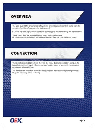
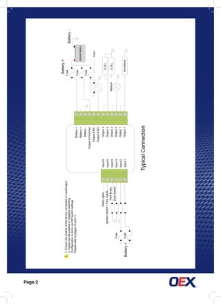
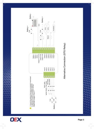

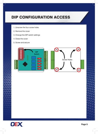
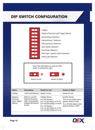
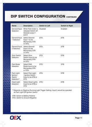
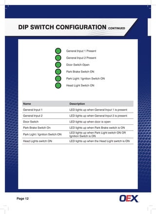


The Safe Guard 64 is an advanced safety device that utilizes microcontroller technology to control safety parameters and warn the operator if a parameter is breached. It has 6 inputs and 4 outputs that can be configured via DIP switches. The document provides wiring diagrams, configuration instructions, and testing procedures for functions like park brake alarm and daytime running lights.


![Service Manual for Chery [Electrical Circuit].pdf](https://cdn.slidesharecdn.com/ss_thumbnails/servicemanualforcheryelectricalcircuit-240708091605-4a1197f7-thumbnail.jpg?width=640&height=640&fit=bounds)


