This document provides instructions for various instrumentation features in a vehicle, including:
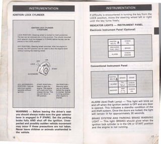
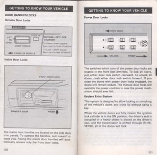
- The ignition lock cylinder has five positions - Lock, Off, Accessory, Start, and On.
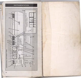
- Warning lights on the instrument panel indicate issues with seat belts, brakes, charging system, oil level, fuel level, and more.
- Gauges display speed, engine temperature, fuel level, and other vehicle data.
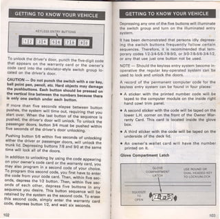
- The anti-theft system arms when the key is removed and doors are locked, and includes an audio and visual alarm.