This document provides installation instructions for the Crime Guard 850i5 car alarm and remote start system. It includes:
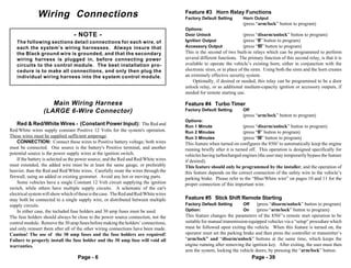
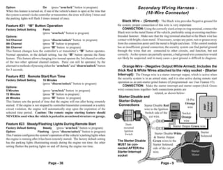
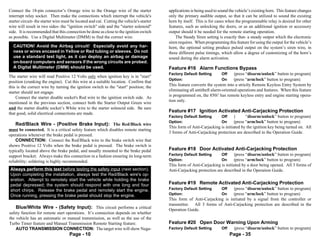
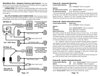
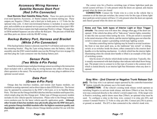
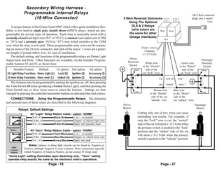
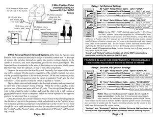
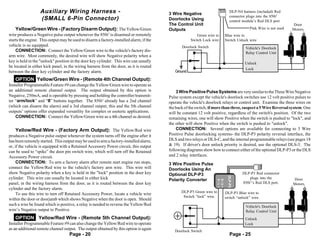
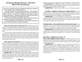
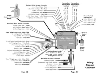
- Wiring diagrams and installation considerations for mounting components and connecting the main, secondary, and auxiliary wiring harnesses.
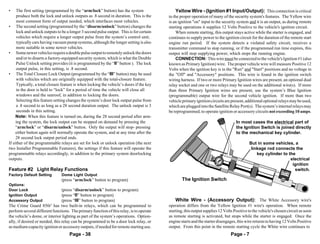
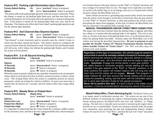
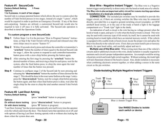
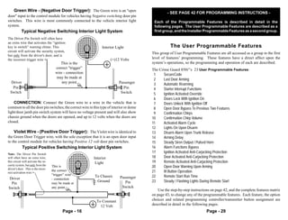
- Descriptions of programmable features for users and installers, including settings for alarm functions, remote start operation, and door locks.
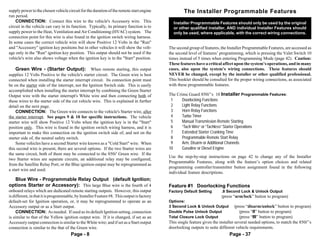
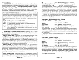
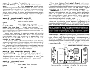
- A complete matrix listing all programmable features and their default and optional settings that can be adjusted through the status light and valet switch on the control module.


![Examenes[1]](https://cdn.slidesharecdn.com/ss_thumbnails/examenes1-100113215531-phpapp01-thumbnail.jpg?width=640&height=640&fit=bounds)


![Presentacion1]](https://cdn.slidesharecdn.com/ss_thumbnails/presentacion1-090518110749-phpapp02-thumbnail.jpg?width=640&height=640&fit=bounds)


