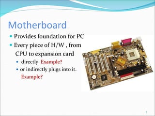
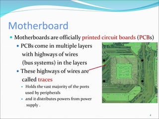
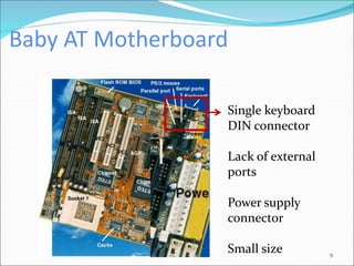
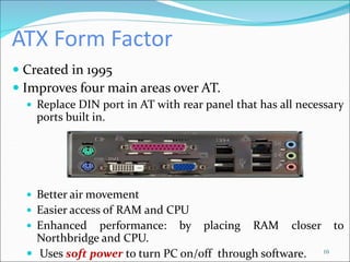
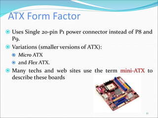
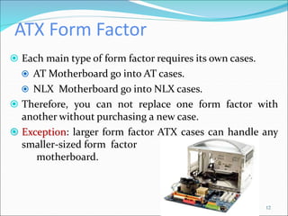
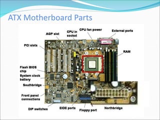
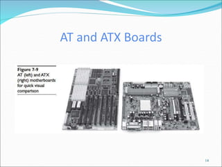
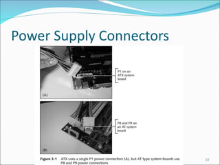
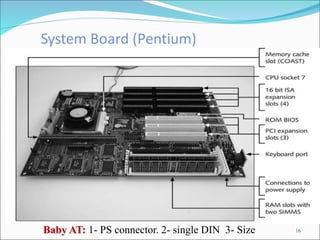
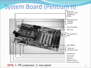
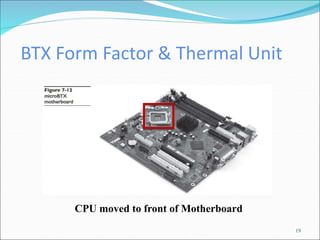
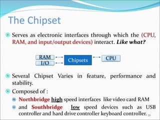
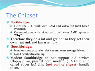
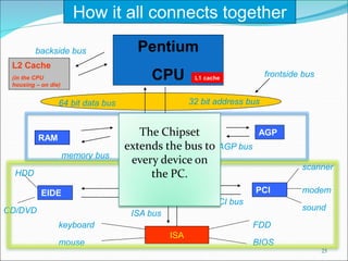
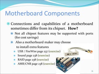
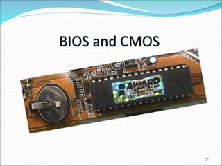
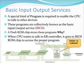
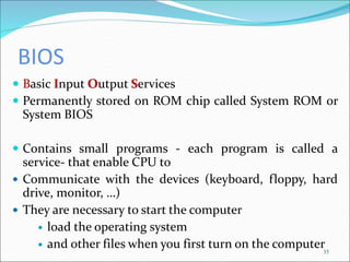
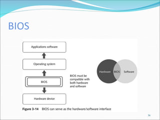
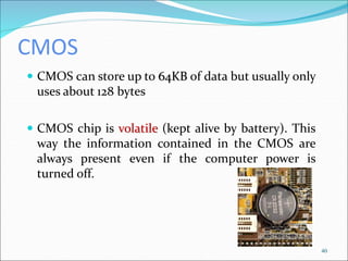
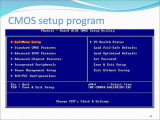
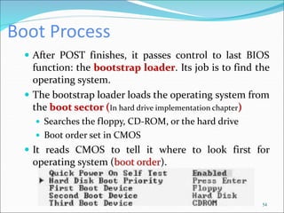
Overview
 In this chapter, you will learn to
 Explain how motherboards work
 Identify the types of motherboards
 Explain chipset varieties
Motherboard
3
 Provides foundation for PC
 Every piece of H/W , from
CPU to expansion card
 directly Example?
 or indirectly plugs into it.
Example?
Motherboard
 Motherboards are officially printed circuit boards (PCBs)
 PCBs come in multiple layers
with highways of wires
(bus systems) in the layers
 These highways of wires are
called traces
 Holds the vast majority of the ports
used by peripherals
 and it distributes powers from power
supply .
4
Motherboard Characteristics
 Three interrelated characteristics define modern
motherboards :
 Form Factor defines
› Physical Size of the motherboard.
› General location of components and parts.
 Chipset defines
› Type of processor and RAM supported.
› Determine the internal and external devices supported by
the motherboard.
 Built-in components
› Determine the core functionality of the system.
Form Factors
 Industry standardized shapes and layouts that enable
motherboards to work with cases and power supplies.
6
 A single form factor applies to all 3 components
(motherboard, power supply, and case).
 You need to install a motherboard in a case designed to fit it, so
ports and slot opening in the back fit correctly
 Power supply and motherboard need
matching connectors.
Form Factors
7
 The PC industry construct a number of form factors
over the years with name such as:
 AT
 ATX
 BTX
 And others.
AT Form Factor
 Used P8 and P9 connectors to power the motherboard
 Single keyboard DIN or (PS1) connector
 Lack of external ports
 Distinguished by position of the keyboard
plug and power socket
 Now: obsolete
 Has a few size variations:
 Baby AT is the most common (Pentium)
 Full AT
 LPX and NLX.
8
Baby AT Motherboard
9
Single keyboard
DIN connector
Lack of external
ports
Power supply
connector
Small size
ATX Form Factor
 Created in 1995
 Improves four main areas over AT.
 Replace DIN port in AT with rear panel that has all necessary
ports built in.
 Better air movement
 Easier access of RAM and CPU
 Enhanced performance: by placing RAM closer to
Northbridge and CPU.
 Uses soft power to turn PC on/off through software. 10
ATX Form Factor
 Uses Single 20-pin P1 power connector instead of P8 and
P9.
 Variations (smaller versions of ATX):
 Micro ATX
 and Flex ATX.
 Many techs and web sites use the term mini-ATX to
describe these boards
11
ATX Form Factor
 Each main type of form factor requires its own cases.
 AT Motherboard go into AT cases.
 NLX Motherboard go into NLX cases.
 Therefore, you can not replace one form factor with
another without purchasing a new case.
 Exception: larger form factor ATX cases can handle any
smaller-sized form factor
motherboard.
12
ATX Motherboard Parts
AT and ATX Boards
14
Power Supply Connectors
15
16
Baby AT: 1- PS connector. 2- single DIN 3- Size
17
ATX: 1- PS connector. 2- rear panel
BTX Form Factor
 BTX (Balanced Technology Extended)
 Due to heat, cooler form factors needed
 Three subtypes of BTX
› BTX designed to replace ATX
› microBTX designed to replace microATX
› picoBTX designed to replace FlexATX
 Its look like ATX but you can not put a BTX
motherboard in an ATX case. Why?
 BTX does not change the power connection, so there
is no such thing as a BTX power supply.
18
BTX Form Factor & Thermal Unit
19
CPU moved to front of Motherboard
The Chipset
 Serves as electronic interfaces through which the (CPU,
RAM, and input/output devices) interact. Like what?
 Several Chipset Varies in feature, performance and
stability.
 Composed of :
 Northbridge high speed interfaces like video card RAM
 and Southbridge low speed devices such as USB
controller and hard drive controller keyboard controller. 20
Chipsets
RAM CPU
I/O
The Chipset
 Northbridge:
 Helps the CPU work with RAM and video (on Intel-based
systems).
 Communicates with video card on newer AMD systems.
Why?
 Therefore they do a lot and get hot so they get their
own heat sink and fan assembly.
 Southbridge:
 handles some expansion devices and mass storage drives.
 Don’t need extra cooling.
 Modern Southbridge do not support old devices
(floppy drive, parallel port, modem,..). A third chip
called Super I/O chip (not part of chipset) handle
them. 21
The Chipset
 Not always called Northbridge and Southbridge
 Intel-based motherboards may refer to them as:
 Memory Controller Hub (MCH) for Northbridge
 and I/O Controller Hub (ICH) for Southbridge.
22
The Chipset
23
 The system ROM chip provides part of the BIOS for
the chipset. It is not sufficient.
 You have to load the proper drivers for the specific OS
to support all features of today’s chipsets.
 All motherboard ship with a CD-ROM disc with
drivers.
Chip Set Manufacturers
 Some of the companies produce chipset designed for
both Intel and AMD CPUs whereas others choose one
or the other company to support.
 Intel Corporation
 AMD, Inc.
 VIA Technology, Inc.
 NVDIA corporation
 SiS
24
25
Pentium
CPU
North Bridge
(Memory Controller)
32 bit address bus
64 bit data bus
frontside bus
L2 Cache
(in the CPU
housing – on die)
backside bus
L1 cache
RAM
memory bus
AGP
AGP bus
South Bridge PCI
PCI bus
scanner
modem
sound
EIDE
ISA
ISA bus
keyboard
mouse
FDD
BIOS
HDD
CD/DVD
How it all connects together
The Chipset
extends the bus to
every device on
the PC.
Motherboard Components
 Connections and capabilities of a motherboard
sometimes differ from its chipset. How?
 Not all chipset features may be supported with ports
(for cost savings)
 Also a motherboard maker may choose
to install extra features
 USB / FireWire page 237 (exercise)
 Sound page 238 (exercise)
 RAID page 238 (exercise)
 AMR/CNR page 238 (exercise)
26
27
Overview
 In this chapter, you will learn to
 Explain Read Only Memory
 Explain the function of BIOS
 Distinguish among various CMOS setup utility options
 Describe BIOS and device drivers
What is (ROM)?
 Read Only Memory
 Memory chips that contain data, instructions, or
information that is recorded permanently.
 Data can only be read, cannot be modified
 Nonvolatile — Contents not lost when the computer is
turned off
 Program stored on ROM are known as firmware not a
Software.
Read Only Memory (ROM)
 ROM have different type:
 ROM
 PROM
 Programmable Read-Only Memory (only once)
 Blank ROM on which you can place items permanently
 EPROM
 Erasable PROM by Ultraviolet (every time you want)
 EEPROM
 Electrically Erasable PROM
 A type of PROM containing microcode that a
programmer can erase using electricity.
What is Flash Memory?
 Variation of EEPROM
 Also called flash ROM or flash RAM
 Nonvolatile memory that can be erased electronically
and reprogrammed.
 Stores data and programs on many handheld
computers and devices such as Camera and mobile
phone.
 Flash memory cards
store flash memory on
removable devices
instead of chips
We Need to Talk
32
Placing a number of components into a computer is
useless if CPU can not communicate with them.
Northbridge & Southbridge
33
 Bridges (North, South) connect the devices
 CPU uses address bus to talk to devices
 But , How does it know what to say to them?
Keyboard
controller
chip
Basic Input Output Services
34
 A special kind of Program is required to enable the CPU
to talk to other devices
 These programs are collectively known as the basic
input/output service (BIOS)
 A Flash ROM chip stores these programs Why?
 When CPU wants to talk to KB controller, it goes to BIOS
ROM chip to access the proper program. Similar to
codebook
BIOS
 Basic Input Output Services
 Permanently stored on ROM chip called System ROM or
System BIOS
 Contains small programs - each program is called a
service- that enable CPU to
 Communicate with the devices (keyboard, floppy, hard
drive, monitor, …)
 They are necessary to start the computer
 load the operating system
 and other files when you first turn on the computer35
36
ROM BIOS
 There is One ROM chip on the system board that contains
BIOS.
 Modern motherboards use Flash ROM (you can change the
contents through a very specific process called “flashing the
ROM”) Read about it in book P180
 There exists hundreds of little services (2 to 30 lines of
code each)for communicating with floppy drives, hard
drives, …
37
System BIOS
 ROM chips can store 2 MB although only 65,536 bytes
system are used to store system BIOS.
 Every system BIOS has two types of hardware to support.
 First:
 All hardware that never changes.
 Ex: KB, PC speaker.
 You cannot change keyboard controller chip.
 Second:
 All hardware that might change.
 Ex: RAM (you could add RAM), hard drives (replacing/
adding).
 The system ROM stores the BIOS for them, but it needs
another place to store information about the specific details of
them CMOS 38
CMOS
 A separate memory chip, called Complementary Metal-
Oxide Semiconductor (CMOS) chip stores the
information that describes specific device parameters.
 CMOS does not store programs, only data that is read by
BIOS to be able to talk to the changeable hardware.
 CMOS also acts as a clock to keep date and time
 Years ago: CMOS was in separate chip.
 Today: CMOS is built into Southbridge.
39
CMOS
 CMOS can store up to 64KB of data but usually only
uses about 128 bytes
 CMOS chip is volatile (kept alive by battery). This
way the information contained in the CMOS are
always present even if the computer power is
turned off.
40
CMOS
 Stores only changeable data.
 Customizable via SETUP program.
 If data in CMOS about certain hardware is different
from its actual specs, PC can not access that
hardware.
 If you change one of changeable devices,
parameters have to be changed in CMOS  how to
change data on CMOS?
41
CMOS SETUP Program
 Special program that allows you to access and update
CMOS data
 Stored on system ROM (BIOS)
 Companies that write the BIOS and how to access
CMOS at boot:
 Phoenix Technologies - Ctrl Alt Esc
 Award Software - uses DEL key
 American Megatrends (AMI) - DEL key
 Other key combinations are: Ctrl Alt Ins, Ctrl A, Ctrl S,
Ctrl F1, or F10
42
Accessing Award SETUP
43
CMOS setup program
44
CMOS setup program
 Exercise: how to access CMOS setup on your PC and
what are the available options?
 Caution: it is perfectly fine to access the CMOS setup
program, but do not make changes unless you fully
understand the system
45
BIOS and device drivers
 PC designers understood that they could not anticipate
every new type of H/W.
 Therefore, they gave us ways to add programs for new
devices other than on the BIOS. It is called BYOB
(Bring Your Own BIOS)
 Ex: Mice, Sound cards,….
 Two ways to BYOB:
 Option ROM (hardware solution)
 and device driver (software solution)
46
Option ROM
47
 Embedded the BIOS in a ROM on the hardware device
itself.
 Today only video card contains its own BIOS.
 Most devices use more flexible software method (device
derivers).
Device drivers
 A device driver is a file that contains the BIOS commands
necessary to communicate with the devices they support
stored on the PC’s hard drive.
 Operating system loads these drivers into RAM when
booting
 They come with the device - in a CD- when you buy it.
 The generic name for CD is installation disc
48
Registry
 A special database –used by windows- that stores
everything you want to know about your system,
including device drivers.
 Use device manager utility to access registry. You can
manually change/remove and drivers
 Exercise: how to use device manager?
49
50
Device Manger
POST
 The power-on self test (POST) is a special program stored
on the ROM chip (BIOS)
 Initiated when the computer is turned on or is reset
 Checks out the system every time the computer boots
 POST program sends out a standard command that says
to all the devices “check yourselves out”.
 All standard devices run their own internal diagnostics.
Quality?
 PCs convey POST information to user in two ways:
 beep codes
 or text message (more useful)
 Exercise: study more about beep codes and text message
51
System ROM Responsibility
 System ROM contains:
 BIOS routines
 CMOS setup program
 POST
52
Basic Boot Process (Step)
 Once the power is turned on, the PC “pulls itself up by
its bootstraps”
 First component to wake up is the CPU.
 By reads a special wire called power good wire once the
power supply provides the certain voltage to the CPU
 Built in memory address is sent on address bus.
 This address represent the first line of POST program on
the system ROM
 POST is run
 If problem happen beep code or text message displayed.
53
Boot Process
 After POST finishes, it passes control to last BIOS
function: the bootstrap loader. Its job is to find the
operating system.
 The bootstrap loader loads the operating system from
the boot sector (In hard drive implementation chapter)
 Searches the floppy, CD-ROM, or the hard drive
 Boot order set in CMOS
 It reads CMOS to tell it where to look first for
operating system (boot order).
54
Boot Process
 If the device is bootable (called system disk), its boot
sector will contain special programming designed to
tell the system where to locate the operating system.
 If bootstrap loader locates a good boot sector, it passes
control to operating system and removes itself from
memory.
 Otherwise it goes to next device specified in CMOS.
55
Care and Feeding of CMOS
 If CMOS battery run out of charge, you lose CMOS
information and computer will not boot.
 Any PC made after 2002 will boot to factory default if
the CMOS clears but you will still get error at boot
 CMOS configuration mismatch
 CMOS date/time not set
 No boot device available
 CMOS battery state low. HOW to replace it?
56
Care and Feeding of CMOS
 Common reasons for losing CMOS data
 On-board battery runs out
 Pulling and inserting cards
 Touching the motherboard
 Dropping something on the motherboard
 Dirt on the motherboard
 Faulty power supplies
57
Fix Problem
 To fix these problems:
 Have CMOS setting memorized
 Replace the battery.
 Compare current settings to backup copy
 CMOS save and restore program - CMOSSAVE.
58
Clearing CMOS Settings
59
 To clear the CMOS settings, place the shunt on
the CMOS jumper
 Resets to factory settings
 Resets password

mother-board-and-bios.ppt

  • 2.
    Overview  In thischapter, you will learn to  Explain how motherboards work  Identify the types of motherboards  Explain chipset varieties
  • 3.
    Motherboard 3  Provides foundationfor PC  Every piece of H/W , from CPU to expansion card  directly Example?  or indirectly plugs into it. Example?
  • 4.
    Motherboard  Motherboards areofficially printed circuit boards (PCBs)  PCBs come in multiple layers with highways of wires (bus systems) in the layers  These highways of wires are called traces  Holds the vast majority of the ports used by peripherals  and it distributes powers from power supply . 4
  • 5.
    Motherboard Characteristics  Threeinterrelated characteristics define modern motherboards :  Form Factor defines › Physical Size of the motherboard. › General location of components and parts.  Chipset defines › Type of processor and RAM supported. › Determine the internal and external devices supported by the motherboard.  Built-in components › Determine the core functionality of the system.
  • 6.
    Form Factors  Industrystandardized shapes and layouts that enable motherboards to work with cases and power supplies. 6  A single form factor applies to all 3 components (motherboard, power supply, and case).  You need to install a motherboard in a case designed to fit it, so ports and slot opening in the back fit correctly  Power supply and motherboard need matching connectors.
  • 7.
    Form Factors 7  ThePC industry construct a number of form factors over the years with name such as:  AT  ATX  BTX  And others.
  • 8.
    AT Form Factor Used P8 and P9 connectors to power the motherboard  Single keyboard DIN or (PS1) connector  Lack of external ports  Distinguished by position of the keyboard plug and power socket  Now: obsolete  Has a few size variations:  Baby AT is the most common (Pentium)  Full AT  LPX and NLX. 8
  • 9.
    Baby AT Motherboard 9 Singlekeyboard DIN connector Lack of external ports Power supply connector Small size
  • 10.
    ATX Form Factor Created in 1995  Improves four main areas over AT.  Replace DIN port in AT with rear panel that has all necessary ports built in.  Better air movement  Easier access of RAM and CPU  Enhanced performance: by placing RAM closer to Northbridge and CPU.  Uses soft power to turn PC on/off through software. 10
  • 11.
    ATX Form Factor Uses Single 20-pin P1 power connector instead of P8 and P9.  Variations (smaller versions of ATX):  Micro ATX  and Flex ATX.  Many techs and web sites use the term mini-ATX to describe these boards 11
  • 12.
    ATX Form Factor Each main type of form factor requires its own cases.  AT Motherboard go into AT cases.  NLX Motherboard go into NLX cases.  Therefore, you can not replace one form factor with another without purchasing a new case.  Exception: larger form factor ATX cases can handle any smaller-sized form factor motherboard. 12
  • 13.
  • 14.
    AT and ATXBoards 14
  • 15.
  • 16.
    16 Baby AT: 1-PS connector. 2- single DIN 3- Size
  • 17.
    17 ATX: 1- PSconnector. 2- rear panel
  • 18.
    BTX Form Factor BTX (Balanced Technology Extended)  Due to heat, cooler form factors needed  Three subtypes of BTX › BTX designed to replace ATX › microBTX designed to replace microATX › picoBTX designed to replace FlexATX  Its look like ATX but you can not put a BTX motherboard in an ATX case. Why?  BTX does not change the power connection, so there is no such thing as a BTX power supply. 18
  • 19.
    BTX Form Factor& Thermal Unit 19 CPU moved to front of Motherboard
  • 20.
    The Chipset  Servesas electronic interfaces through which the (CPU, RAM, and input/output devices) interact. Like what?  Several Chipset Varies in feature, performance and stability.  Composed of :  Northbridge high speed interfaces like video card RAM  and Southbridge low speed devices such as USB controller and hard drive controller keyboard controller. 20 Chipsets RAM CPU I/O
  • 21.
    The Chipset  Northbridge: Helps the CPU work with RAM and video (on Intel-based systems).  Communicates with video card on newer AMD systems. Why?  Therefore they do a lot and get hot so they get their own heat sink and fan assembly.  Southbridge:  handles some expansion devices and mass storage drives.  Don’t need extra cooling.  Modern Southbridge do not support old devices (floppy drive, parallel port, modem,..). A third chip called Super I/O chip (not part of chipset) handle them. 21
  • 22.
    The Chipset  Notalways called Northbridge and Southbridge  Intel-based motherboards may refer to them as:  Memory Controller Hub (MCH) for Northbridge  and I/O Controller Hub (ICH) for Southbridge. 22
  • 23.
    The Chipset 23  Thesystem ROM chip provides part of the BIOS for the chipset. It is not sufficient.  You have to load the proper drivers for the specific OS to support all features of today’s chipsets.  All motherboard ship with a CD-ROM disc with drivers.
  • 24.
    Chip Set Manufacturers Some of the companies produce chipset designed for both Intel and AMD CPUs whereas others choose one or the other company to support.  Intel Corporation  AMD, Inc.  VIA Technology, Inc.  NVDIA corporation  SiS 24
  • 25.
    25 Pentium CPU North Bridge (Memory Controller) 32bit address bus 64 bit data bus frontside bus L2 Cache (in the CPU housing – on die) backside bus L1 cache RAM memory bus AGP AGP bus South Bridge PCI PCI bus scanner modem sound EIDE ISA ISA bus keyboard mouse FDD BIOS HDD CD/DVD How it all connects together The Chipset extends the bus to every device on the PC.
  • 26.
    Motherboard Components  Connectionsand capabilities of a motherboard sometimes differ from its chipset. How?  Not all chipset features may be supported with ports (for cost savings)  Also a motherboard maker may choose to install extra features  USB / FireWire page 237 (exercise)  Sound page 238 (exercise)  RAID page 238 (exercise)  AMR/CNR page 238 (exercise) 26
  • 27.
  • 28.
    Overview  In thischapter, you will learn to  Explain Read Only Memory  Explain the function of BIOS  Distinguish among various CMOS setup utility options  Describe BIOS and device drivers
  • 29.
    What is (ROM)? Read Only Memory  Memory chips that contain data, instructions, or information that is recorded permanently.  Data can only be read, cannot be modified  Nonvolatile — Contents not lost when the computer is turned off  Program stored on ROM are known as firmware not a Software.
  • 30.
    Read Only Memory(ROM)  ROM have different type:  ROM  PROM  Programmable Read-Only Memory (only once)  Blank ROM on which you can place items permanently  EPROM  Erasable PROM by Ultraviolet (every time you want)  EEPROM  Electrically Erasable PROM  A type of PROM containing microcode that a programmer can erase using electricity.
  • 31.
    What is FlashMemory?  Variation of EEPROM  Also called flash ROM or flash RAM  Nonvolatile memory that can be erased electronically and reprogrammed.  Stores data and programs on many handheld computers and devices such as Camera and mobile phone.  Flash memory cards store flash memory on removable devices instead of chips
  • 32.
    We Need toTalk 32 Placing a number of components into a computer is useless if CPU can not communicate with them.
  • 33.
    Northbridge & Southbridge 33 Bridges (North, South) connect the devices  CPU uses address bus to talk to devices  But , How does it know what to say to them? Keyboard controller chip
  • 34.
    Basic Input OutputServices 34  A special kind of Program is required to enable the CPU to talk to other devices  These programs are collectively known as the basic input/output service (BIOS)  A Flash ROM chip stores these programs Why?  When CPU wants to talk to KB controller, it goes to BIOS ROM chip to access the proper program. Similar to codebook
  • 35.
    BIOS  Basic InputOutput Services  Permanently stored on ROM chip called System ROM or System BIOS  Contains small programs - each program is called a service- that enable CPU to  Communicate with the devices (keyboard, floppy, hard drive, monitor, …)  They are necessary to start the computer  load the operating system  and other files when you first turn on the computer35
  • 36.
  • 37.
    ROM BIOS  Thereis One ROM chip on the system board that contains BIOS.  Modern motherboards use Flash ROM (you can change the contents through a very specific process called “flashing the ROM”) Read about it in book P180  There exists hundreds of little services (2 to 30 lines of code each)for communicating with floppy drives, hard drives, … 37
  • 38.
    System BIOS  ROMchips can store 2 MB although only 65,536 bytes system are used to store system BIOS.  Every system BIOS has two types of hardware to support.  First:  All hardware that never changes.  Ex: KB, PC speaker.  You cannot change keyboard controller chip.  Second:  All hardware that might change.  Ex: RAM (you could add RAM), hard drives (replacing/ adding).  The system ROM stores the BIOS for them, but it needs another place to store information about the specific details of them CMOS 38
  • 39.
    CMOS  A separatememory chip, called Complementary Metal- Oxide Semiconductor (CMOS) chip stores the information that describes specific device parameters.  CMOS does not store programs, only data that is read by BIOS to be able to talk to the changeable hardware.  CMOS also acts as a clock to keep date and time  Years ago: CMOS was in separate chip.  Today: CMOS is built into Southbridge. 39
  • 40.
    CMOS  CMOS canstore up to 64KB of data but usually only uses about 128 bytes  CMOS chip is volatile (kept alive by battery). This way the information contained in the CMOS are always present even if the computer power is turned off. 40
  • 41.
    CMOS  Stores onlychangeable data.  Customizable via SETUP program.  If data in CMOS about certain hardware is different from its actual specs, PC can not access that hardware.  If you change one of changeable devices, parameters have to be changed in CMOS  how to change data on CMOS? 41
  • 42.
    CMOS SETUP Program Special program that allows you to access and update CMOS data  Stored on system ROM (BIOS)  Companies that write the BIOS and how to access CMOS at boot:  Phoenix Technologies - Ctrl Alt Esc  Award Software - uses DEL key  American Megatrends (AMI) - DEL key  Other key combinations are: Ctrl Alt Ins, Ctrl A, Ctrl S, Ctrl F1, or F10 42
  • 43.
  • 44.
  • 45.
    CMOS setup program Exercise: how to access CMOS setup on your PC and what are the available options?  Caution: it is perfectly fine to access the CMOS setup program, but do not make changes unless you fully understand the system 45
  • 46.
    BIOS and devicedrivers  PC designers understood that they could not anticipate every new type of H/W.  Therefore, they gave us ways to add programs for new devices other than on the BIOS. It is called BYOB (Bring Your Own BIOS)  Ex: Mice, Sound cards,….  Two ways to BYOB:  Option ROM (hardware solution)  and device driver (software solution) 46
  • 47.
    Option ROM 47  Embeddedthe BIOS in a ROM on the hardware device itself.  Today only video card contains its own BIOS.  Most devices use more flexible software method (device derivers).
  • 48.
    Device drivers  Adevice driver is a file that contains the BIOS commands necessary to communicate with the devices they support stored on the PC’s hard drive.  Operating system loads these drivers into RAM when booting  They come with the device - in a CD- when you buy it.  The generic name for CD is installation disc 48
  • 49.
    Registry  A specialdatabase –used by windows- that stores everything you want to know about your system, including device drivers.  Use device manager utility to access registry. You can manually change/remove and drivers  Exercise: how to use device manager? 49
  • 50.
  • 51.
    POST  The power-onself test (POST) is a special program stored on the ROM chip (BIOS)  Initiated when the computer is turned on or is reset  Checks out the system every time the computer boots  POST program sends out a standard command that says to all the devices “check yourselves out”.  All standard devices run their own internal diagnostics. Quality?  PCs convey POST information to user in two ways:  beep codes  or text message (more useful)  Exercise: study more about beep codes and text message 51
  • 52.
    System ROM Responsibility System ROM contains:  BIOS routines  CMOS setup program  POST 52
  • 53.
    Basic Boot Process(Step)  Once the power is turned on, the PC “pulls itself up by its bootstraps”  First component to wake up is the CPU.  By reads a special wire called power good wire once the power supply provides the certain voltage to the CPU  Built in memory address is sent on address bus.  This address represent the first line of POST program on the system ROM  POST is run  If problem happen beep code or text message displayed. 53
  • 54.
    Boot Process  AfterPOST finishes, it passes control to last BIOS function: the bootstrap loader. Its job is to find the operating system.  The bootstrap loader loads the operating system from the boot sector (In hard drive implementation chapter)  Searches the floppy, CD-ROM, or the hard drive  Boot order set in CMOS  It reads CMOS to tell it where to look first for operating system (boot order). 54
  • 55.
    Boot Process  Ifthe device is bootable (called system disk), its boot sector will contain special programming designed to tell the system where to locate the operating system.  If bootstrap loader locates a good boot sector, it passes control to operating system and removes itself from memory.  Otherwise it goes to next device specified in CMOS. 55
  • 56.
    Care and Feedingof CMOS  If CMOS battery run out of charge, you lose CMOS information and computer will not boot.  Any PC made after 2002 will boot to factory default if the CMOS clears but you will still get error at boot  CMOS configuration mismatch  CMOS date/time not set  No boot device available  CMOS battery state low. HOW to replace it? 56
  • 57.
    Care and Feedingof CMOS  Common reasons for losing CMOS data  On-board battery runs out  Pulling and inserting cards  Touching the motherboard  Dropping something on the motherboard  Dirt on the motherboard  Faulty power supplies 57
  • 58.
    Fix Problem  Tofix these problems:  Have CMOS setting memorized  Replace the battery.  Compare current settings to backup copy  CMOS save and restore program - CMOSSAVE. 58
  • 59.
    Clearing CMOS Settings 59 To clear the CMOS settings, place the shunt on the CMOS jumper  Resets to factory settings  Resets password