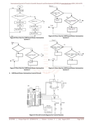
The document presents a GSM-based home appliance control system utilizing Android technology to remotely manage devices like lights, fans, and sliding doors through SMS communication. It outlines the design, hardware components including Arduino Uno, GSM module, and various sensors, and details the system's operations and communication protocols. The authors highlight the efficiency and convenience of wireless home automation and express gratitude to their academic advisors for support throughout the project.
![International Journal of Trend in Scientific Research and Development (IJTSRD)
Volume 3 Issue 5, August 2019 Available Online: www.ijtsrd.com e-ISSN: 2456 – 6470
@ IJTSRD | Unique Paper ID – IJTSRD26743 | Volume – 3 | Issue – 5 | July - August 2019 Page 1675
GSM Based Home Appliance Control System
Mrs Khin Ei Ei Khine, Mr Nay Soe Shwe, Mr Aung Myo Naing
Master of Engineering, Technological University, Hmawbi, Yangon, Myanmar
How to cite this paper: Mrs Khin Ei Ei
Khine | Mr Nay Soe Shwe | Mr Aung Myo
Naing "GSM Based Home Appliance
Control System"
Published in
International
Journal of Trend in
Scientific Research
and Development
(ijtsrd), ISSN: 2456-
6470, Volume-3 |
Issue-5, August 2019, pp.1675-1680,
https://doi.org/10.31142/ijtsrd26743
Copyright © 2019 by author(s) and
International Journalof Trendin Scientific
Research and Development Journal. This
is an Open Access article distributed
under the terms of
the Creative
CommonsAttribution
License (CC BY 4.0)
(http://creativecommons.org/licenses/by
/4.0)
ABSTRACT
In this paper, describes about how to control home appliances, auto door
sliding motor, fan and lighting using GSM technology by using android
application through android mobile phone. Performing of these tasks with a
single android device makes every faster because the android makes SMS
communication. This paper serve as a basic structure of the communication
control system. The programming is done door operating system,hedge light-
bulbs and fan and light-bulbs inside the home.ArduinoUno,Sensorsandserial
communicating devices are incorporated and synchronized with thepersonal
computer.
KEYWORDS: SMS communication, Control System, Sensor, GSM technology,
android mobile phone, Arduino Uno
1. INTRODUCTION
In recent years, the wireless communication is increasing day byday.Thereisa
huge advancement in the communication sector. Any new facilities home
appliances that promise to enhance the life style is grabbed by the consumers.
The more such facilities and appliances are improved, it becomes inevitable to
have easy and convenient methods and means to control and operate these
appliances. Almost all people nowadays have access to mobile phones and thus
the world has indeed become a global village. At any given moment, anyperson
across the world is contacted with the help of a mobile phone.
But mobile phones are not only used for the calling and
sending SMS purposes but also new ideas is generated and
techniques from it that further enhance it capabilities.
Having wireless control of almost all the things in a person’s
life is a growing interest and many systems are providing
such control. This idea has designed a control system which
is based on the GSM technology that effectively allows
control from a remote area to the desired location. Because
of this system, there is no need for a person to physically
present to switch on/off the electricalappliances. Thispaper
represent remotely controlled smart home automation
system, for monitoring and controlling of the home light,
hedge light, fan and sliding door by using GSM phone inside
and outside the home. [1]
The SMS received by the receiver is transmitted to the
Arduino Uno which reads the message and controls the
appropriate device. The SMS received by the receiver is
transmitted to the Arduino Uno which reads the message
and controls the appropriate device. The primary goal is to
discuss home automation technology, lifetime is getting
easier and simpler on all side in life. This technology
proposed to control the home GSM network. The user
commands are transferred to a server, processes the user
commands and sends them to the relevant units. The home
server is built upon a SMS mobile cell module. The system
makes use of Arduino Uno for home appliances control. It
makes use of GSM for control of the appliances in terms of
SMS based system.[2]
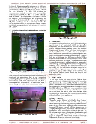
2. SYSTEM DESCRIPTION
The system has two parts, namely; hardware and software.
The hardware architecture consists of
1. Arduino Uno (ATmega328)
2. GSM Shield SIM900A Moderm
3. Limit Switch Sensor
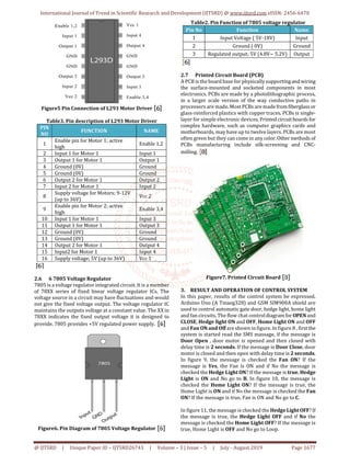
4. 8-channel Relay Module
5. 7805 Voltage Regulator
6. L293 Motor Driver
7. Diode
8. Capacitor
9. Resistor
10. LED
11. Printed Circuit Board (PCB)
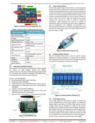
2.1 Arduino Uno (ATmega328)
The Arduino Uno is a microcontroller board based on the
(AT mega 328) as shown in figure-1. It has 14 digital
input/output pins (of which 6 can be used as PWM outputs),
6 analog inputs, a 16 MHz crystal oscillator, a USB
connection, a power jack, an ICSP header, and aresetbutton.
It contains everything needed to support the
microcontroller; simply connect it to a computer with a USB
cable or power it with an AC-to-DC adapter or battery to get
started. This board operates in 5V 40-50mA. This paper has
used an adapter with the Arduino Uno (ATmega328) while
provide the power supply to all the components.
IJTSRD26743](https://image.slidesharecdn.com/317gsmbasedhomeappliancecontrolsystem-190916070839/85/GSM-Based-Home-Appliance-Control-System-1-320.jpg)
![International Journal of Trend in Scientific Research and Development (IJTSRD)
Volume 3 Issue 5, August 2019 Available Online: www.ijtsrd.com e-ISSN: 2456 – 6470
@ IJTSRD | Unique Paper ID – IJTSRD26743 | Volume – 3 | Issue – 5 | July - August 2019 Page 1675
GSM Based Home Appliance Control System
Mrs Khin Ei Ei Khine, Mr Nay Soe Shwe, Mr Aung Myo Naing
Master of Engineering, Technological University, Hmawbi, Yangon, Myanmar
How to cite this paper: Mrs Khin Ei Ei
Khine | Mr Nay Soe Shwe | Mr Aung Myo
Naing "GSM Based Home Appliance
Control System"
Published in
International
Journal of Trend in
Scientific Research
and Development
(ijtsrd), ISSN: 2456-
6470, Volume-3 |
Issue-5, August 2019, pp.1675-1680,
https://doi.org/10.31142/ijtsrd26743
Copyright © 2019 by author(s) and
International Journalof Trendin Scientific
Research and Development Journal. This
is an Open Access article distributed
under the terms of
the Creative
CommonsAttribution
License (CC BY 4.0)
(http://creativecommons.org/licenses/by
/4.0)
ABSTRACT
In this paper, describes about how to control home appliances, auto door
sliding motor, fan and lighting using GSM technology by using android
application through android mobile phone. Performing of these tasks with a
single android device makes every faster because the android makes SMS
communication. This paper serve as a basic structure of the communication
control system. The programming is done door operating system,hedge light-
bulbs and fan and light-bulbs inside the home.ArduinoUno,Sensorsandserial
communicating devices are incorporated and synchronized with thepersonal
computer.
KEYWORDS: SMS communication, Control System, Sensor, GSM technology,
android mobile phone, Arduino Uno
1. INTRODUCTION
In recent years, the wireless communication is increasing day byday.Thereisa
huge advancement in the communication sector. Any new facilities home
appliances that promise to enhance the life style is grabbed by the consumers.
The more such facilities and appliances are improved, it becomes inevitable to
have easy and convenient methods and means to control and operate these
appliances. Almost all people nowadays have access to mobile phones and thus
the world has indeed become a global village. At any given moment, anyperson
across the world is contacted with the help of a mobile phone.
But mobile phones are not only used for the calling and
sending SMS purposes but also new ideas is generated and
techniques from it that further enhance it capabilities.
Having wireless control of almost all the things in a person’s
life is a growing interest and many systems are providing
such control. This idea has designed a control system which
is based on the GSM technology that effectively allows
control from a remote area to the desired location. Because
of this system, there is no need for a person to physically
present to switch on/off the electricalappliances. Thispaper
represent remotely controlled smart home automation
system, for monitoring and controlling of the home light,
hedge light, fan and sliding door by using GSM phone inside
and outside the home. [1]
The SMS received by the receiver is transmitted to the
Arduino Uno which reads the message and controls the
appropriate device. The SMS received by the receiver is
transmitted to the Arduino Uno which reads the message
and controls the appropriate device. The primary goal is to
discuss home automation technology, lifetime is getting
easier and simpler on all side in life. This technology
proposed to control the home GSM network. The user
commands are transferred to a server, processes the user
commands and sends them to the relevant units. The home
server is built upon a SMS mobile cell module. The system
makes use of Arduino Uno for home appliances control. It
makes use of GSM for control of the appliances in terms of
SMS based system.[2]
2. SYSTEM DESCRIPTION
The system has two parts, namely; hardware and software.
The hardware architecture consists of
1. Arduino Uno (ATmega328)
2. GSM Shield SIM900A Moderm
3. Limit Switch Sensor
4. 8-channel Relay Module
5. 7805 Voltage Regulator
6. L293 Motor Driver
7. Diode
8. Capacitor
9. Resistor
10. LED
11. Printed Circuit Board (PCB)
2.1 Arduino Uno (ATmega328)
The Arduino Uno is a microcontroller board based on the
(AT mega 328) as shown in figure-1. It has 14 digital
input/output pins (of which 6 can be used as PWM outputs),
6 analog inputs, a 16 MHz crystal oscillator, a USB
connection, a power jack, an ICSP header, and aresetbutton.
It contains everything needed to support the
microcontroller; simply connect it to a computer with a USB
cable or power it with an AC-to-DC adapter or battery to get
started. This board operates in 5V 40-50mA. This paper has
used an adapter with the Arduino Uno (ATmega328) while
provide the power supply to all the components.
IJTSRD26743](https://image.slidesharecdn.com/317gsmbasedhomeappliancecontrolsystem-190916070839/75/GSM-Based-Home-Appliance-Control-System-1-2048.jpg)
![International Journal of Trend in Scientific Research and Development (IJTSRD) @ www.ijtsrd.com eISSN: 2456-6470
@ IJTSRD | Unique Paper ID – IJTSRD26743 | Volume – 3 | Issue – 5 | July - August 2019 Page 1680
REFERENCES
[1] Wikipedia No Date. , Arduino Uno, Received in August
2018 <https;//en.wikipedia.org/wiki/Arduino Uno>
[2] Wikipedia No Date., Limit Switch Sensor, Received in
August 2018 <https;//en.wikipedia.org/wiki/ Limit
Switch Sensor >
[3] Wikipedia No Date., GSM Shield Sim 900A, Received in
August 2018 <https;//en.wikipedia.org/wiki/ GSM
Shield Sim 900A >
[4] WikipediaNoDate, RelayModule(8-Channel),Received
in August 2018 <https;//en.wikipedia.org/wiki/Relay
Module(8-Channel)>
[5] Wikipedia No Date, Diode, Received in August 2018
<https;//en.wikipedia.org/wiki/ Diode>
[6] Wikipedia No Date. , Bridge Rectifier, Received in
August 2018 <https;//en.wikipedia.org/wiki/ Bridge
Rectifier >
[7] Wikipedia No Date, Light Emitting Diode(LED),
Received in August 2018
<https;//en.wikipedia.org/wiki/ Light Emitting
Diode(LED)>
[8] Wikipedia No Date, Printed Circuit Board(PCB),
Received in August 2018
<https;//en.wikipedia.org/wiki/ Printed Circuit
Board(PCB)>](https://image.slidesharecdn.com/317gsmbasedhomeappliancecontrolsystem-190916070839/85/GSM-Based-Home-Appliance-Control-System-6-320.jpg)