Download to read offline
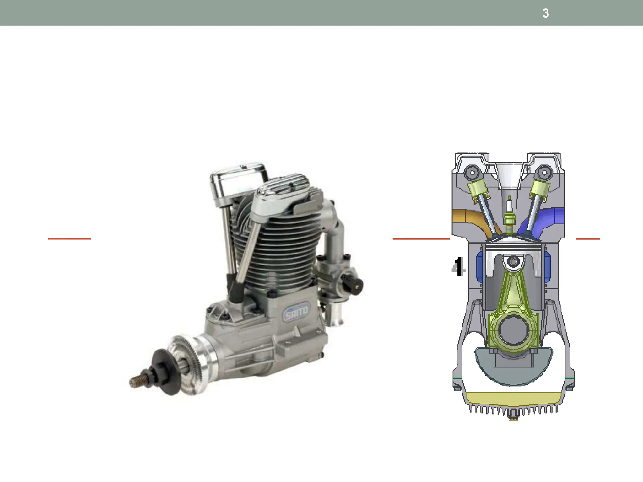
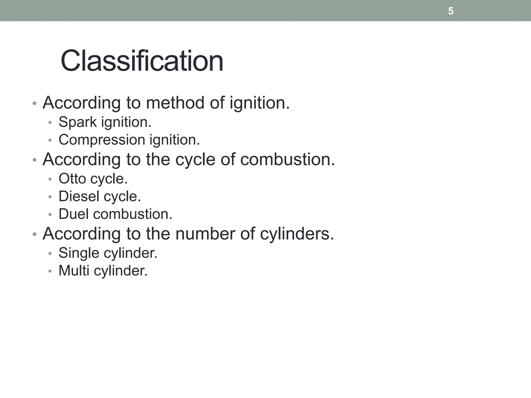

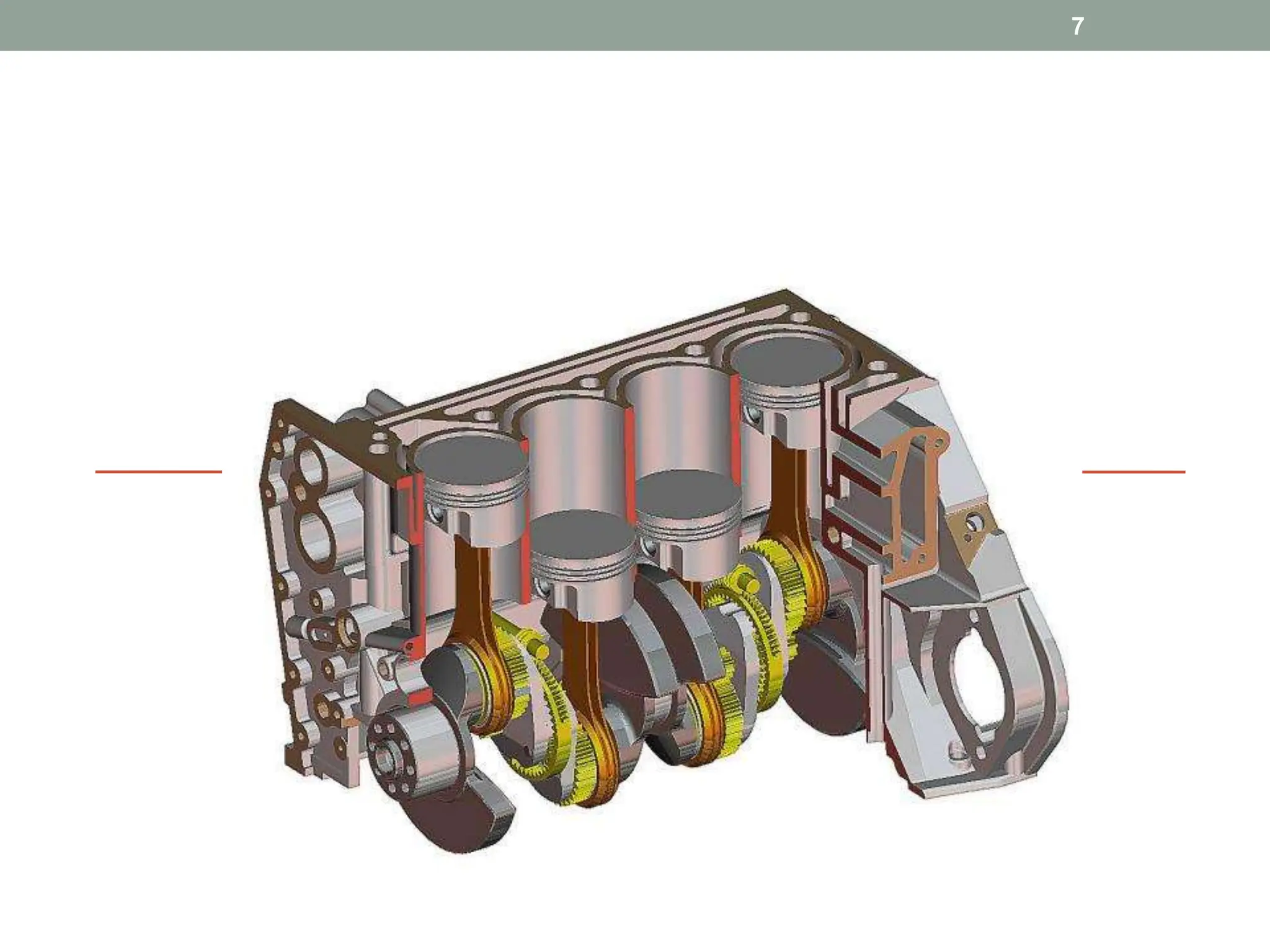
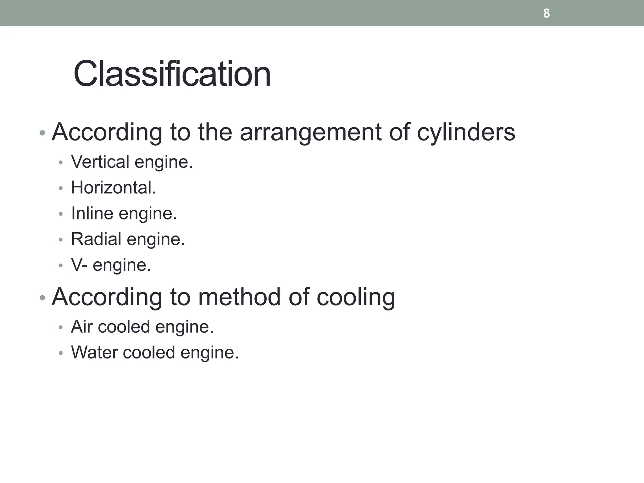
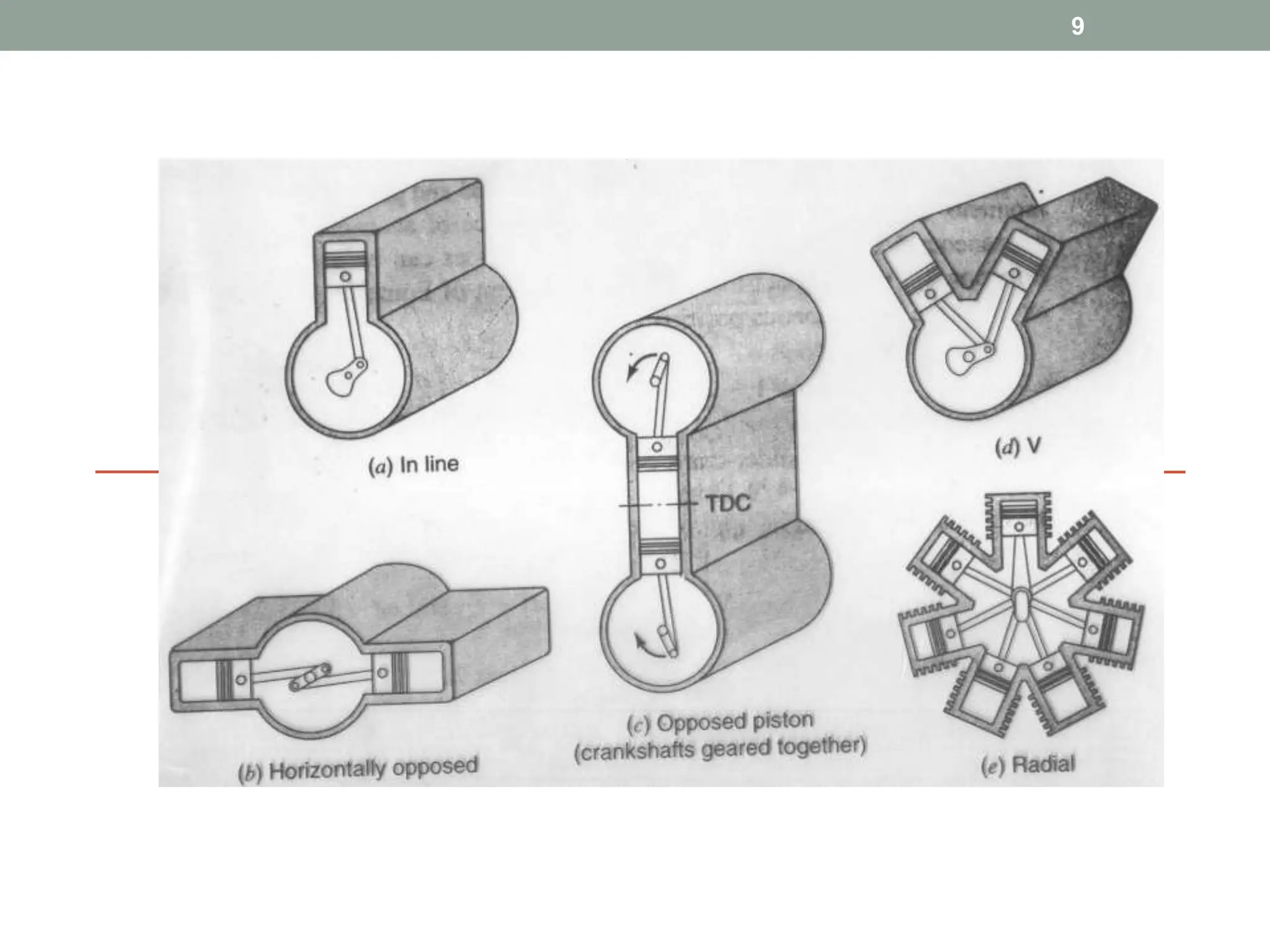
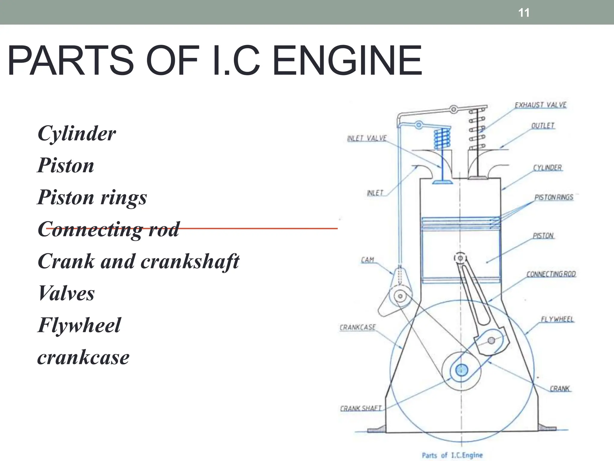
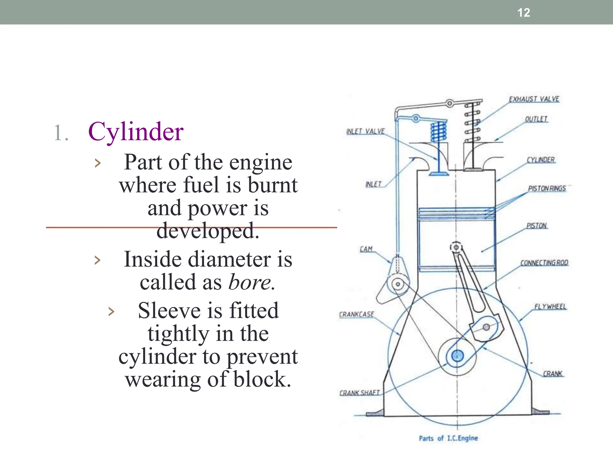

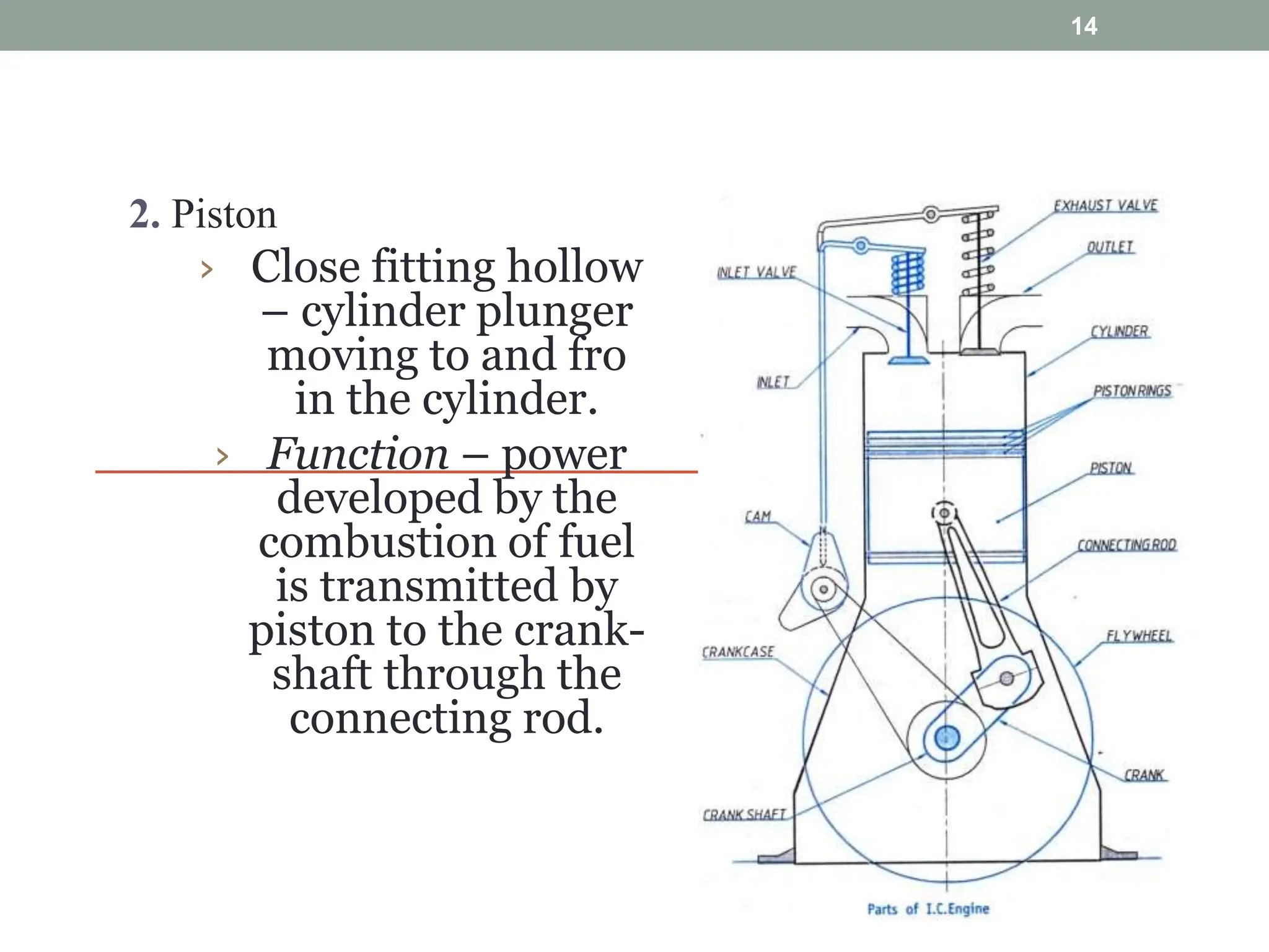

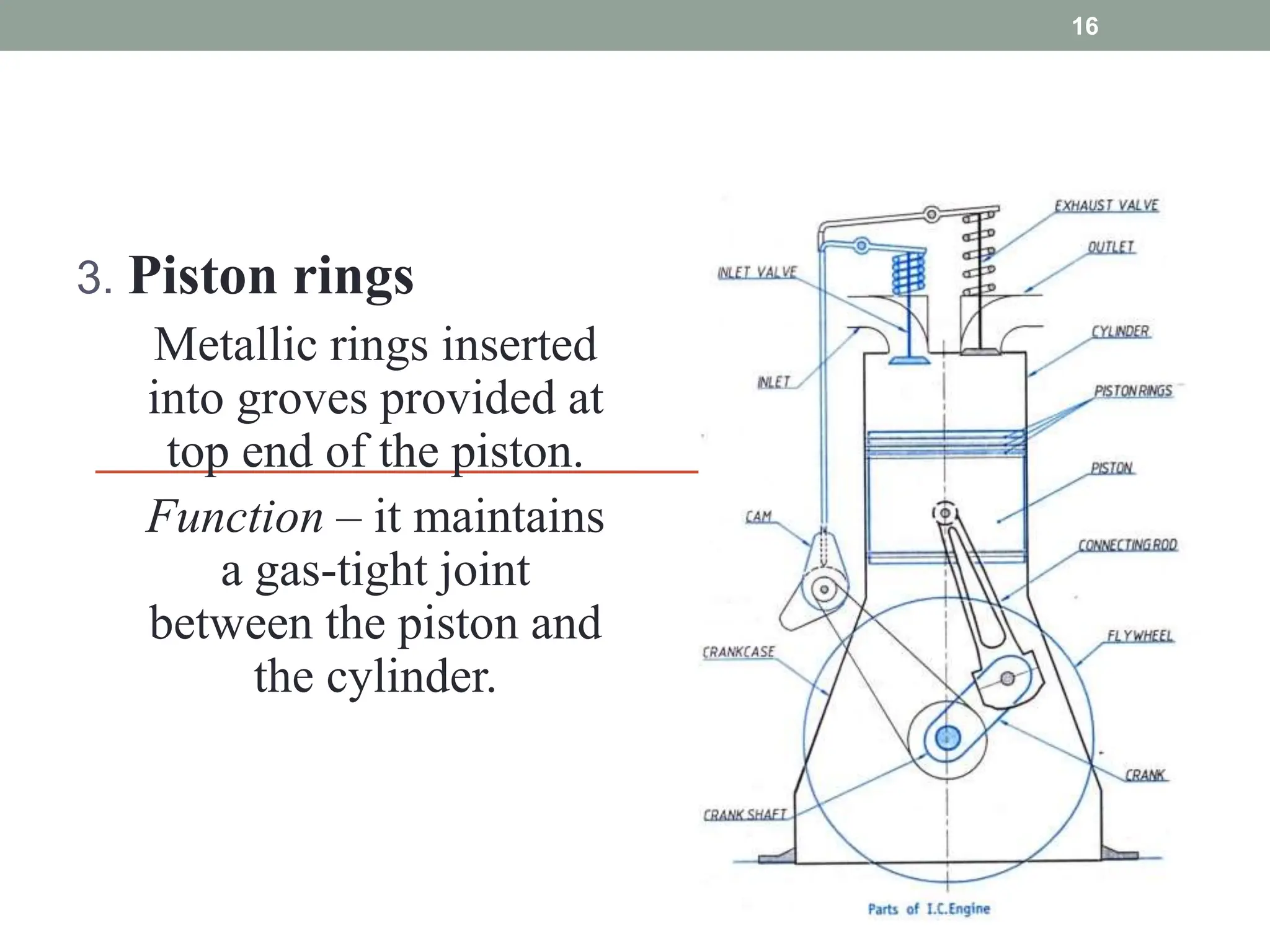
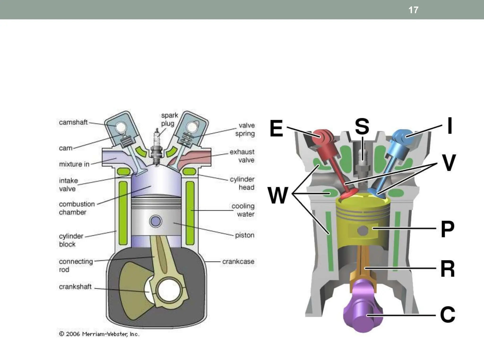
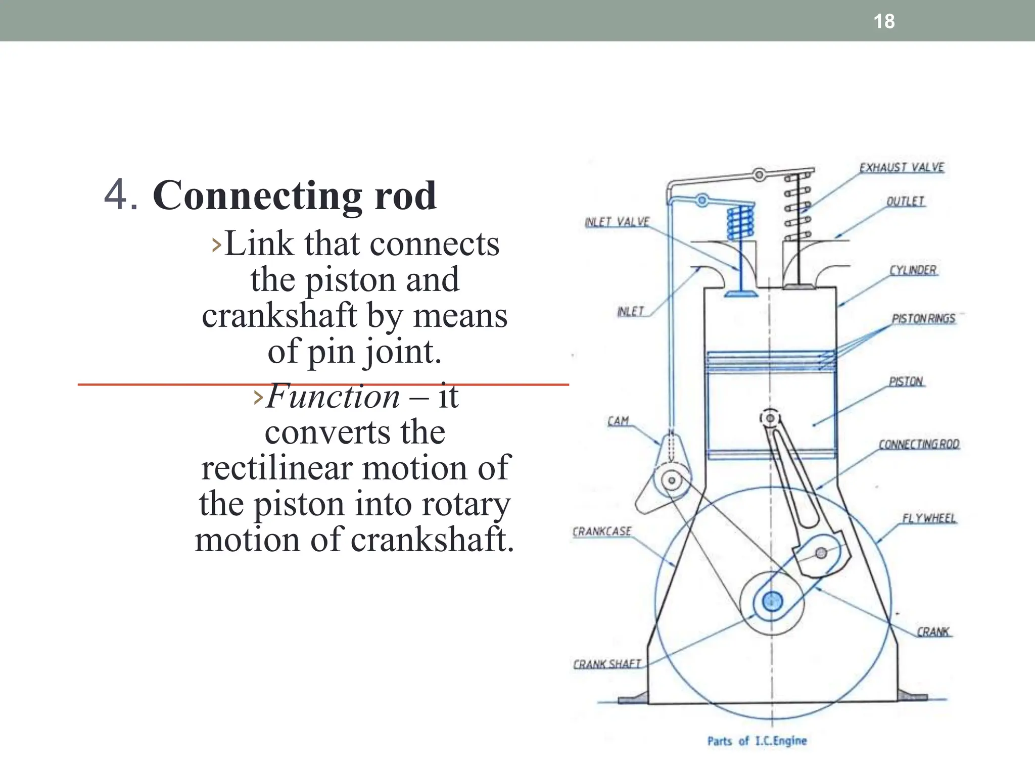

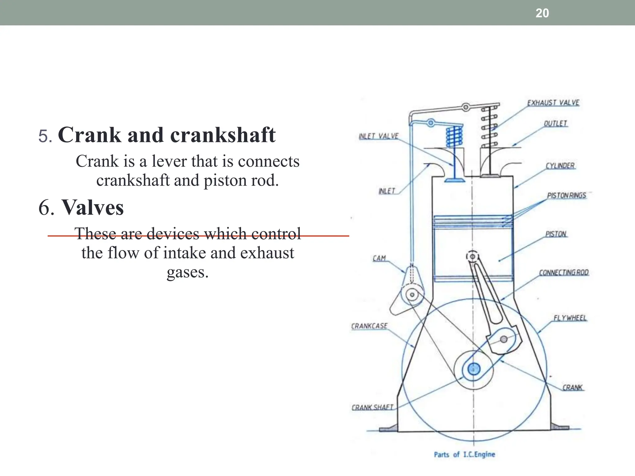

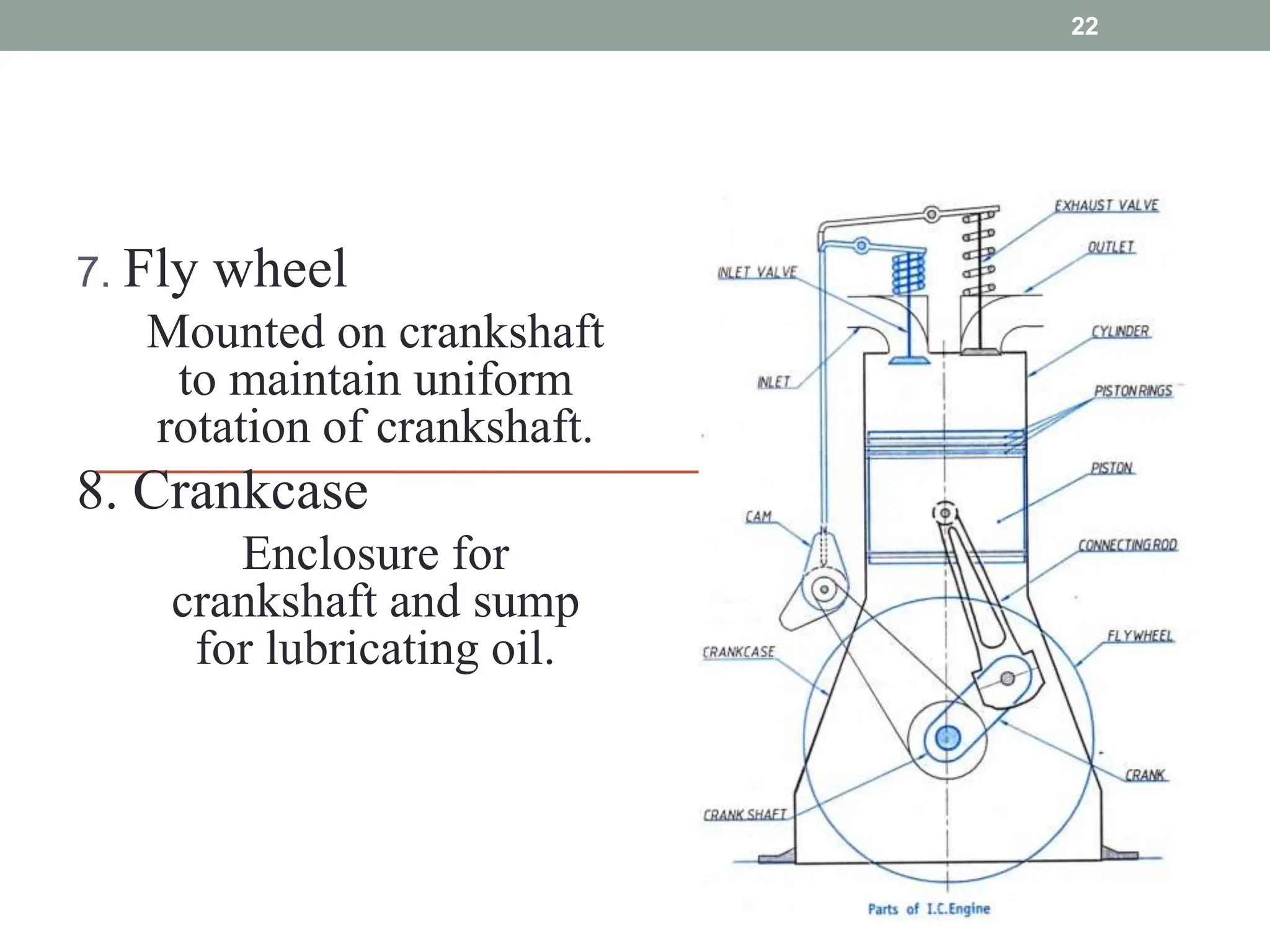
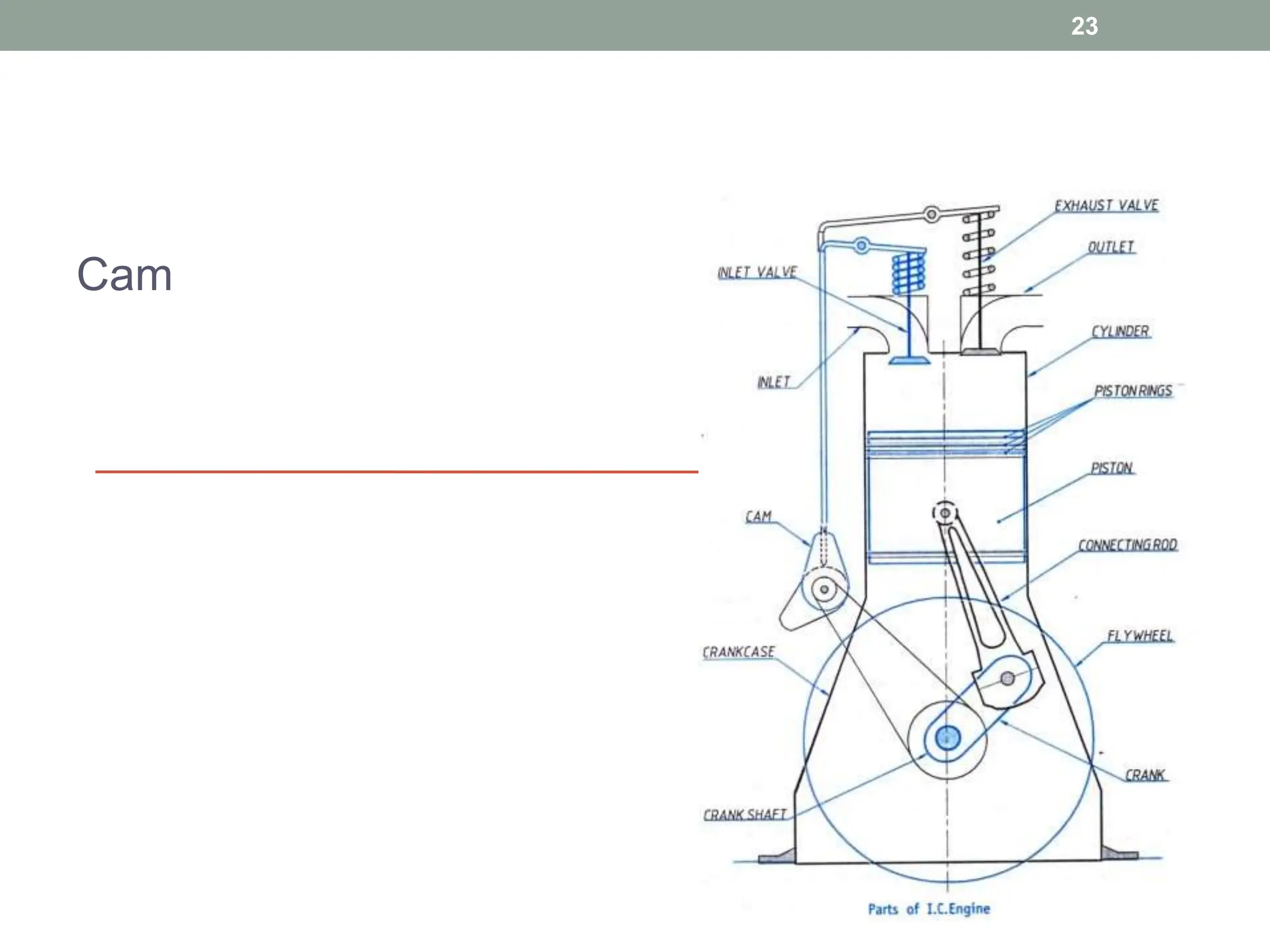
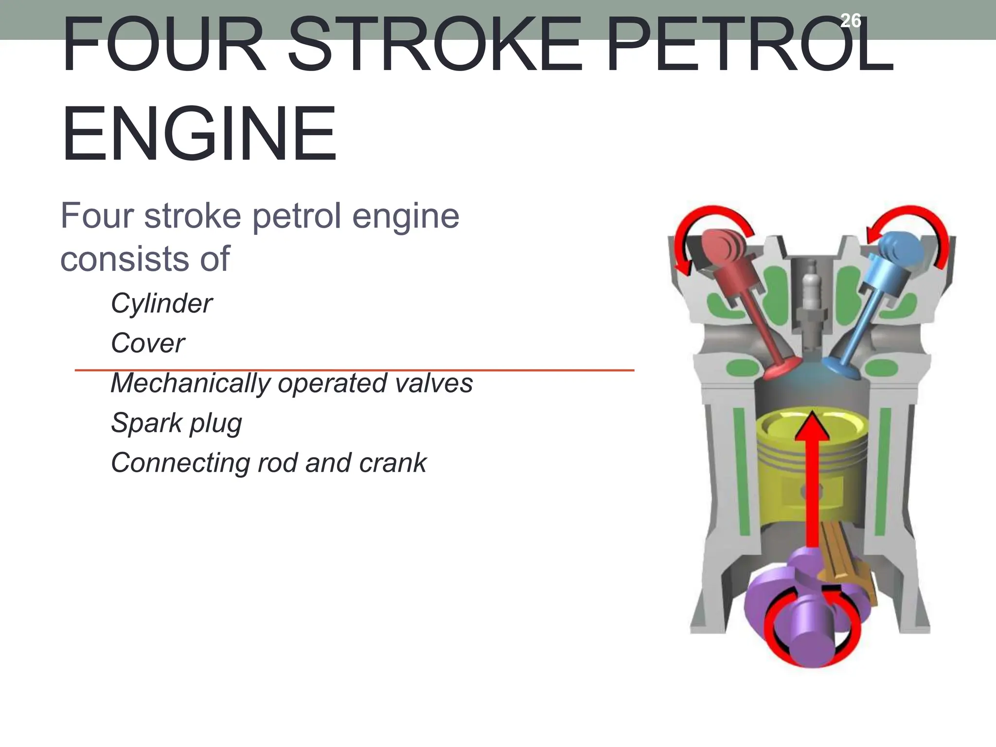
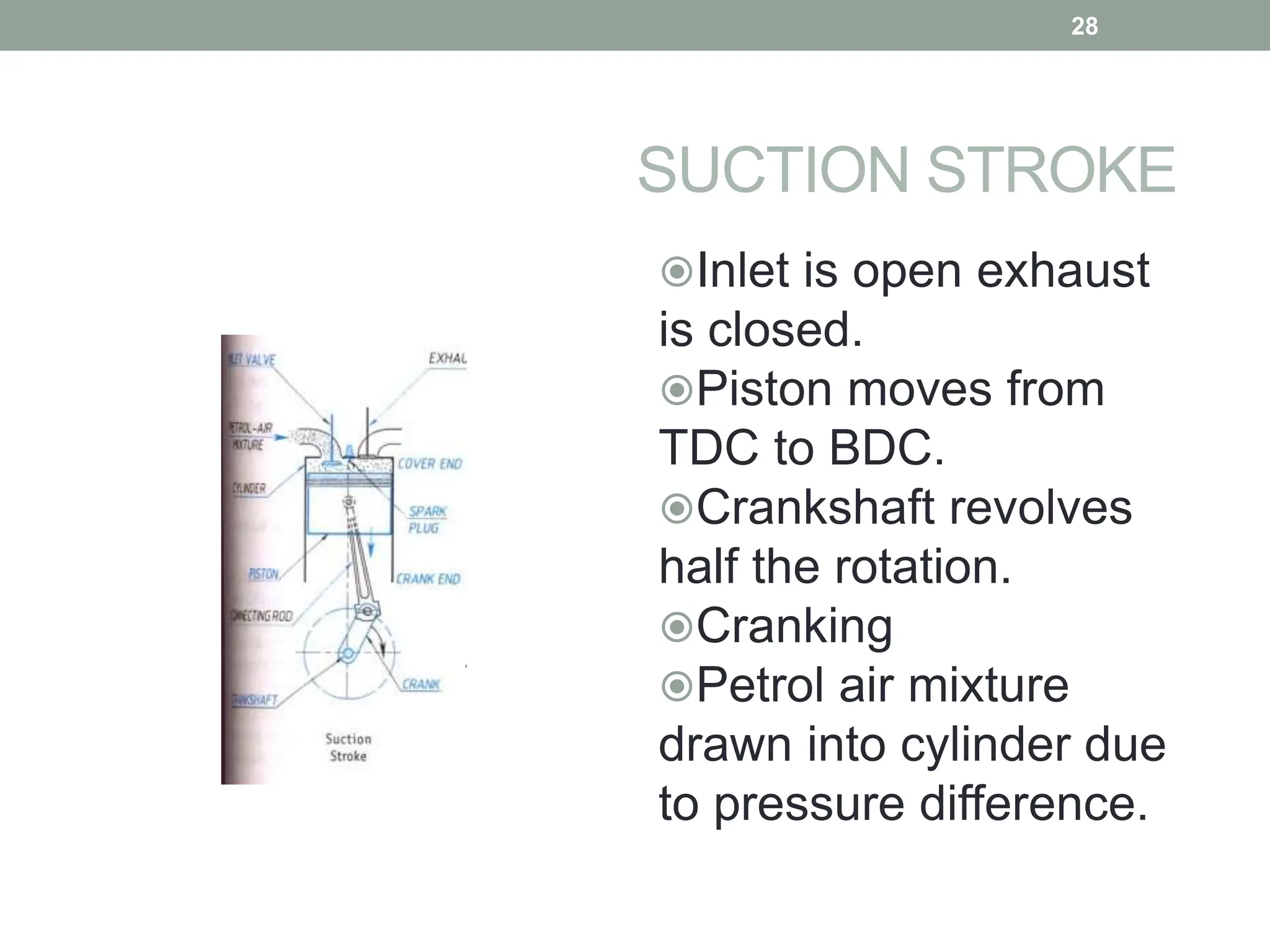
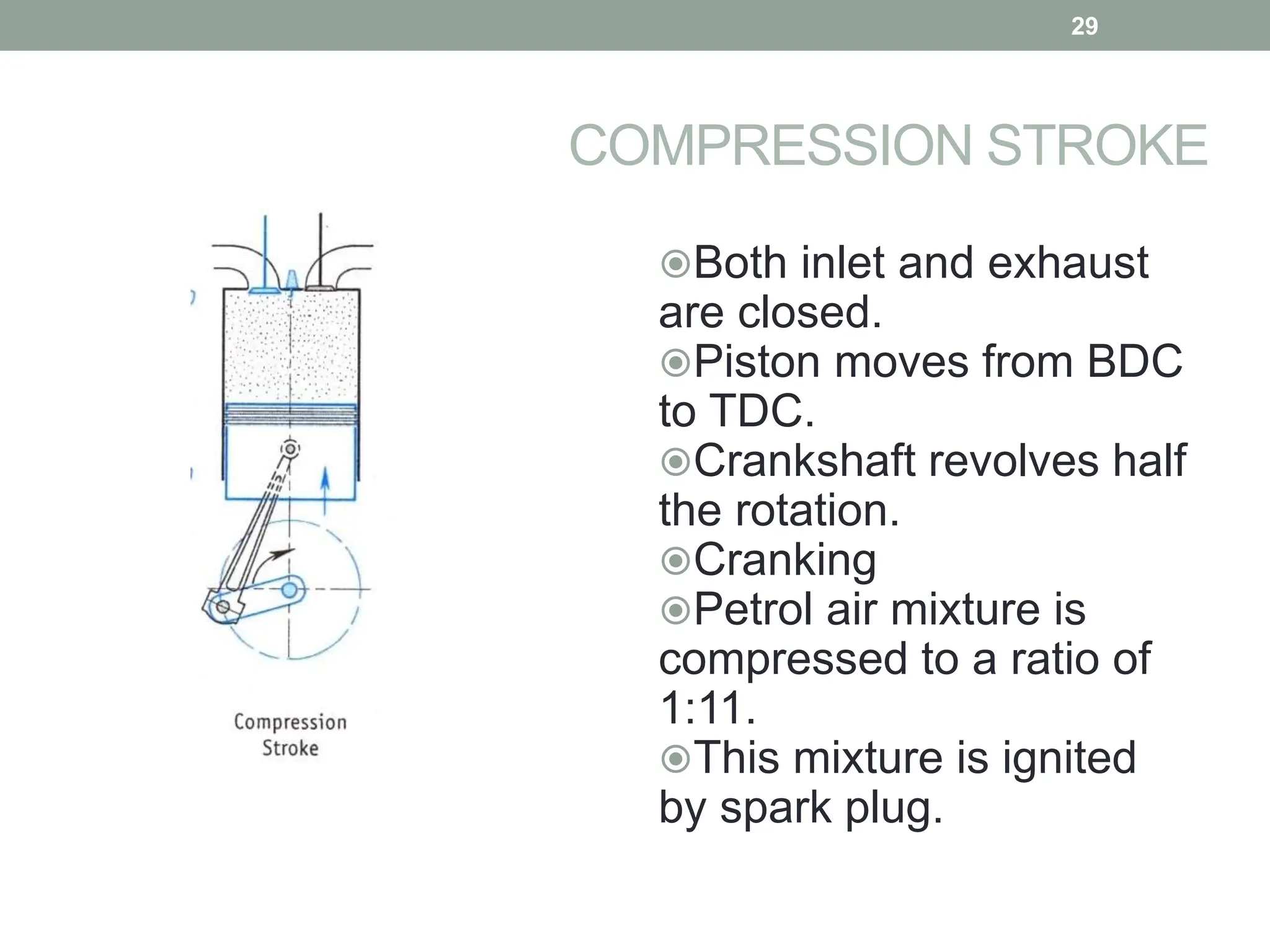
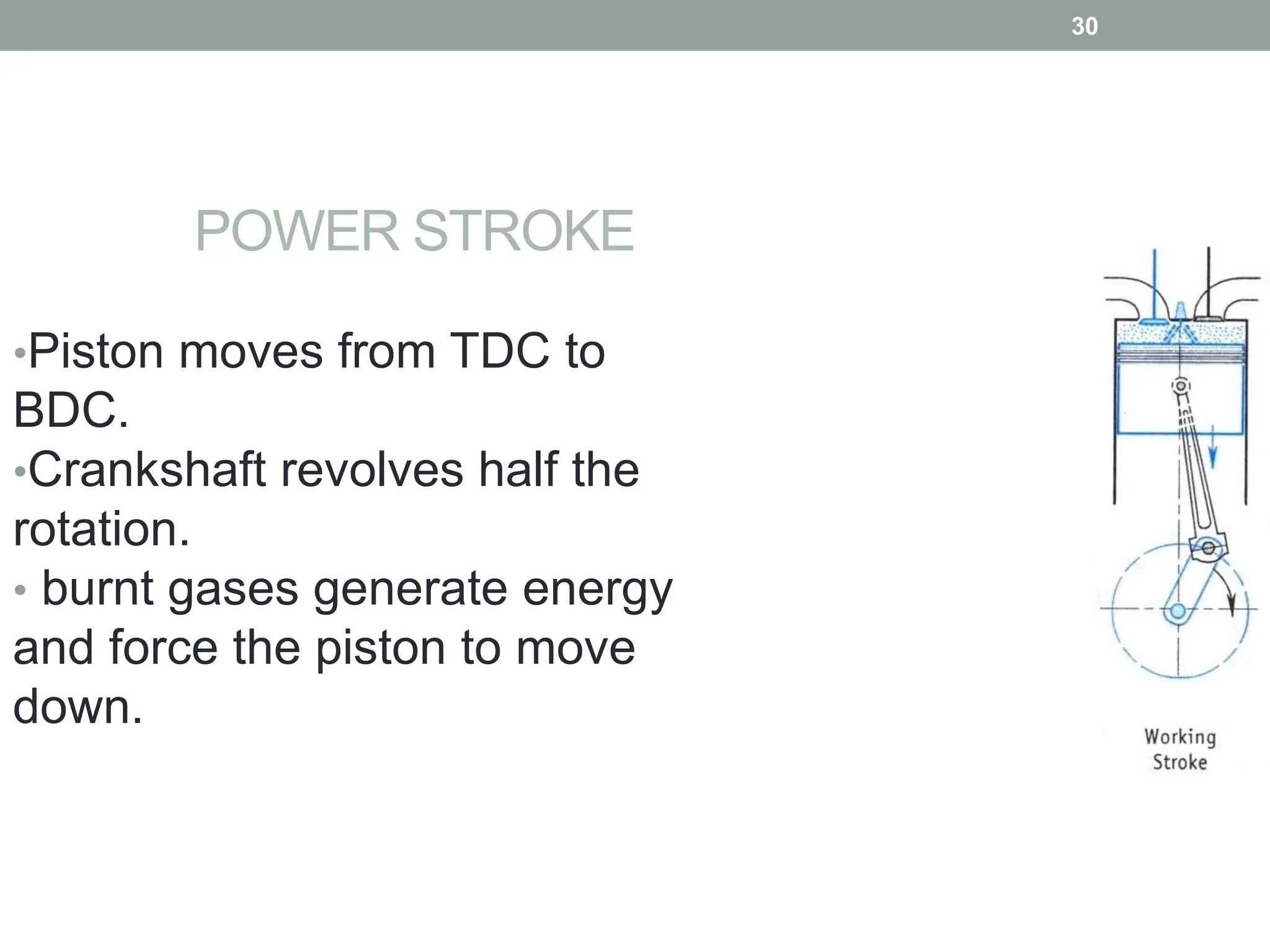
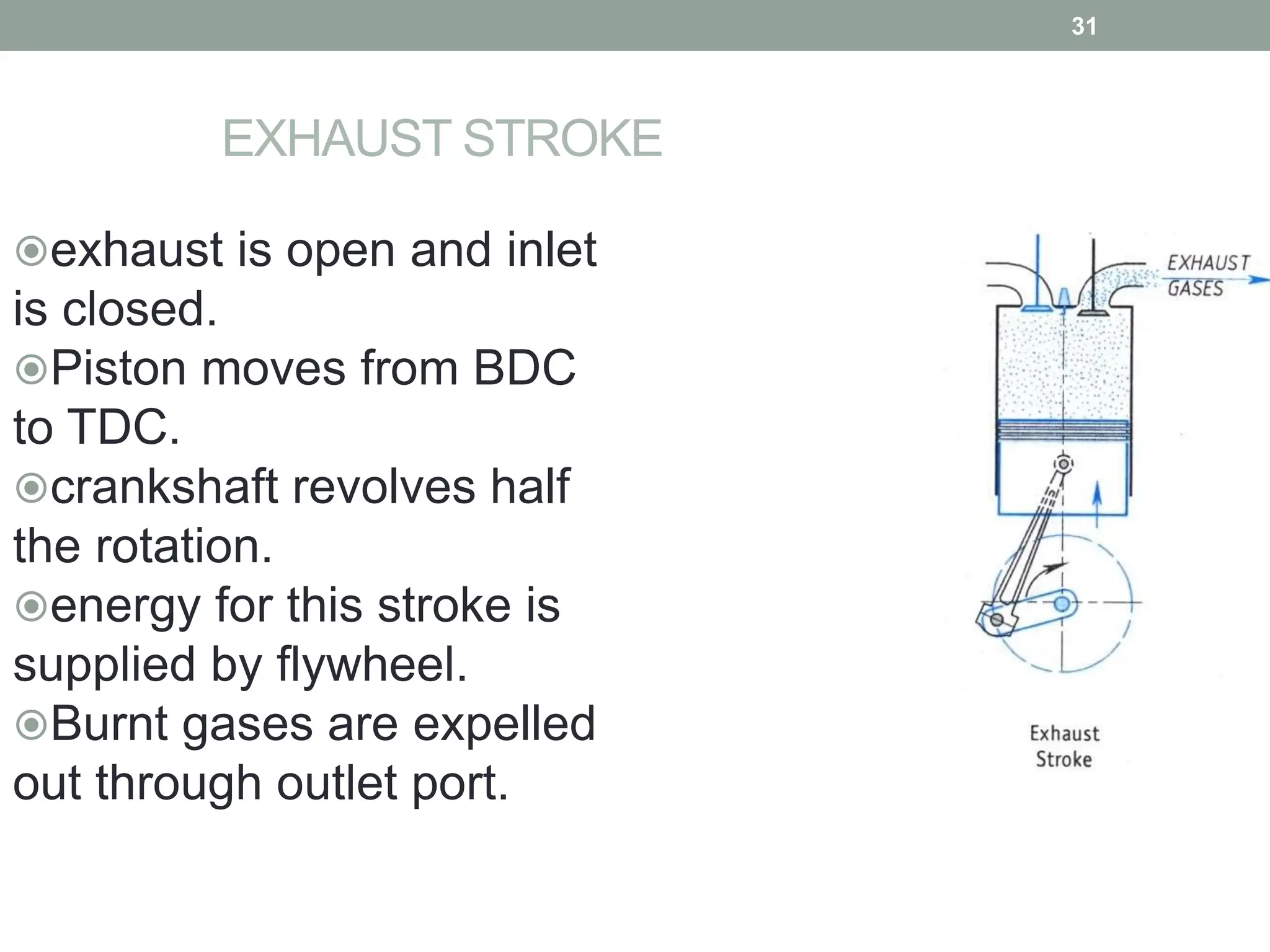
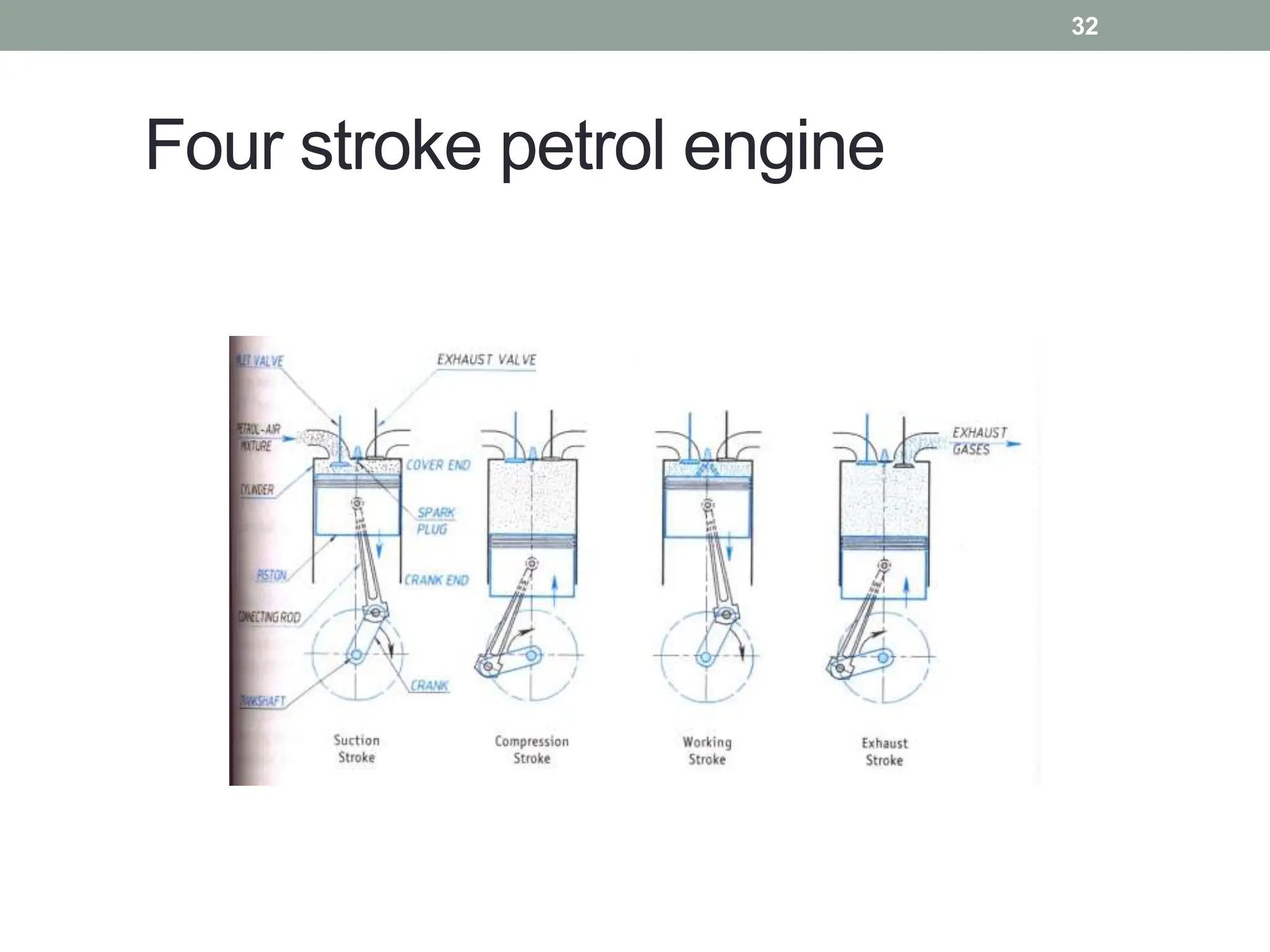
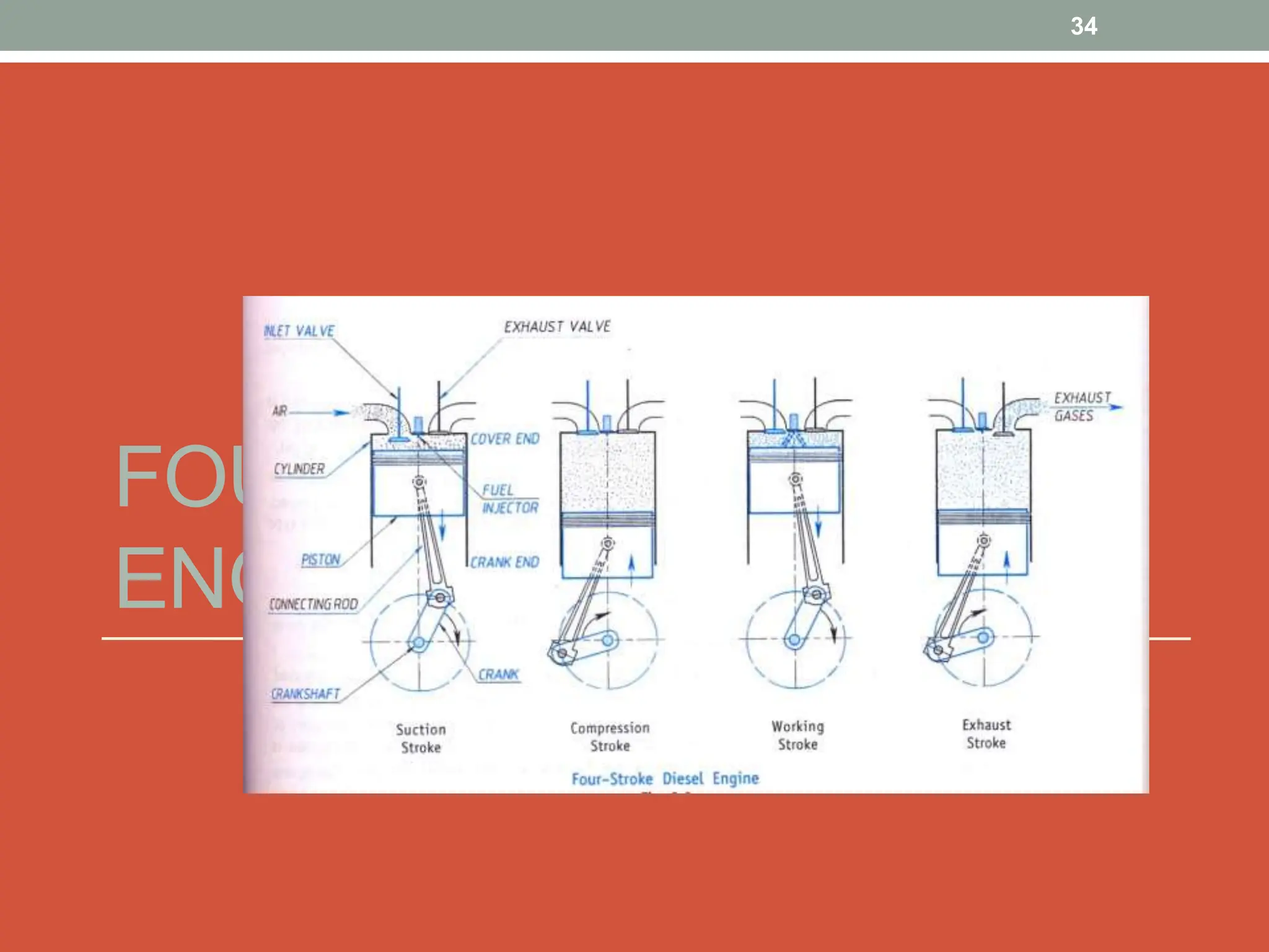

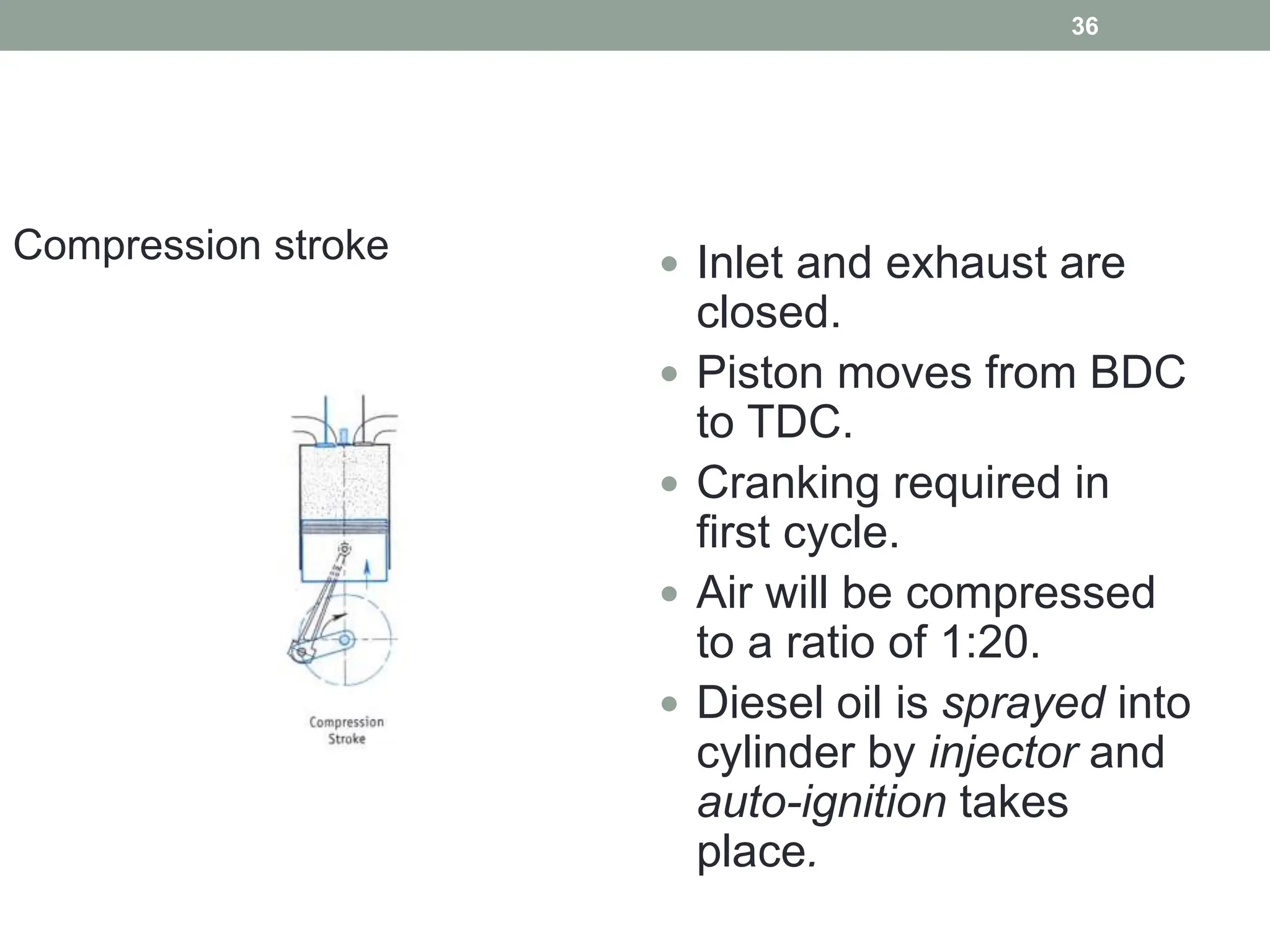
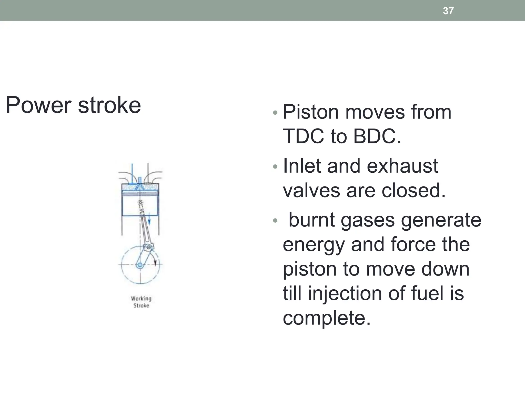
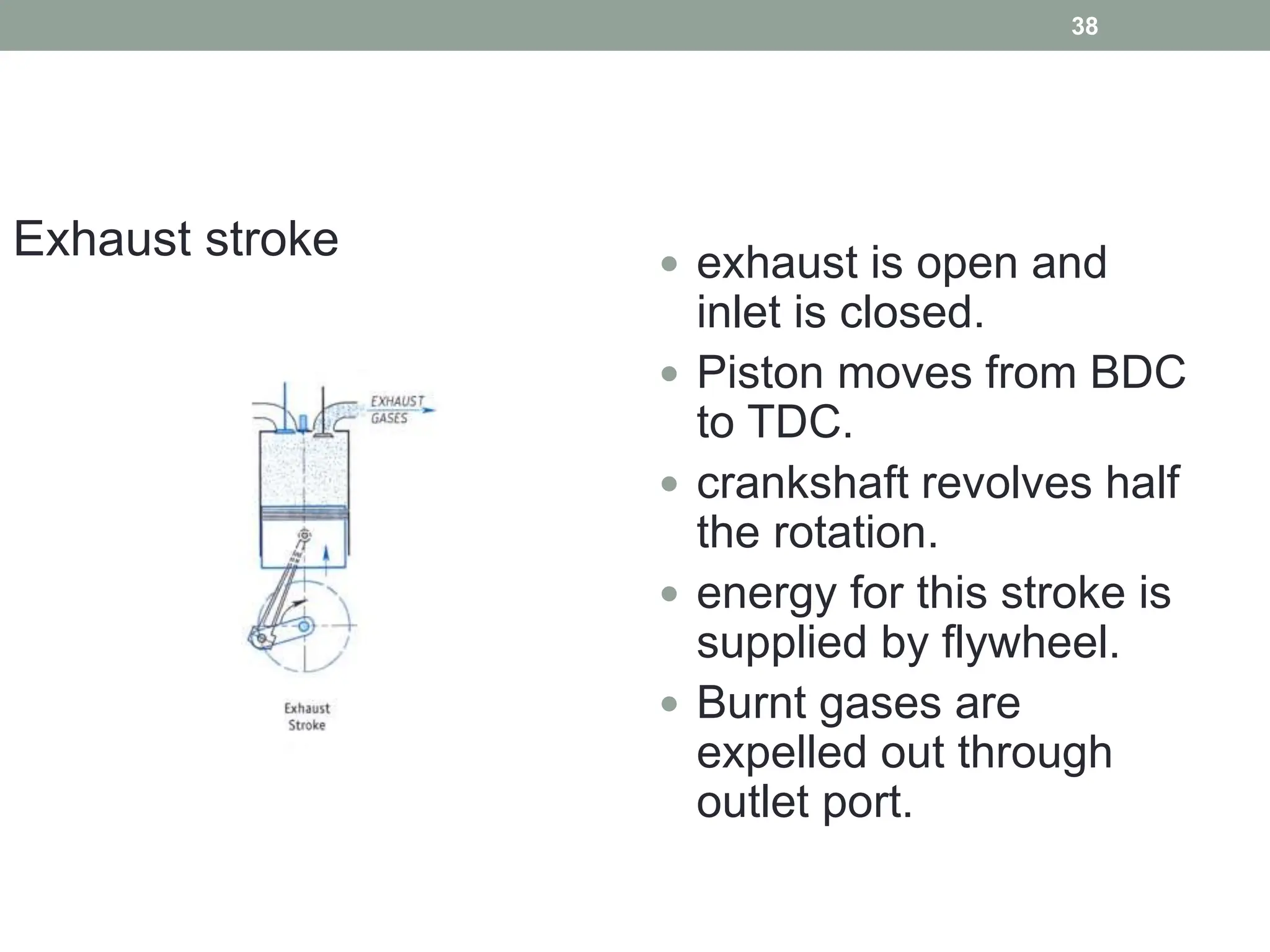
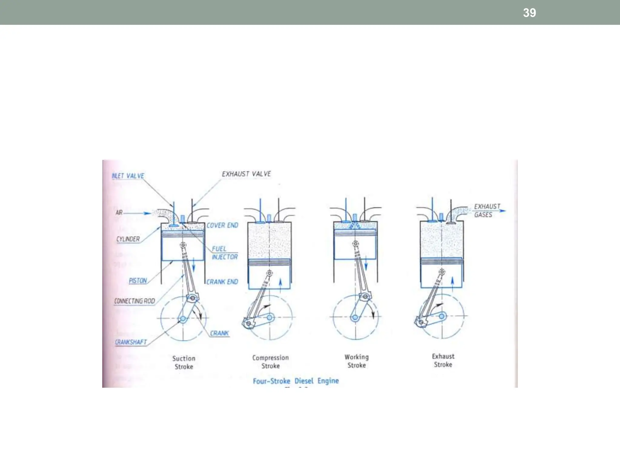
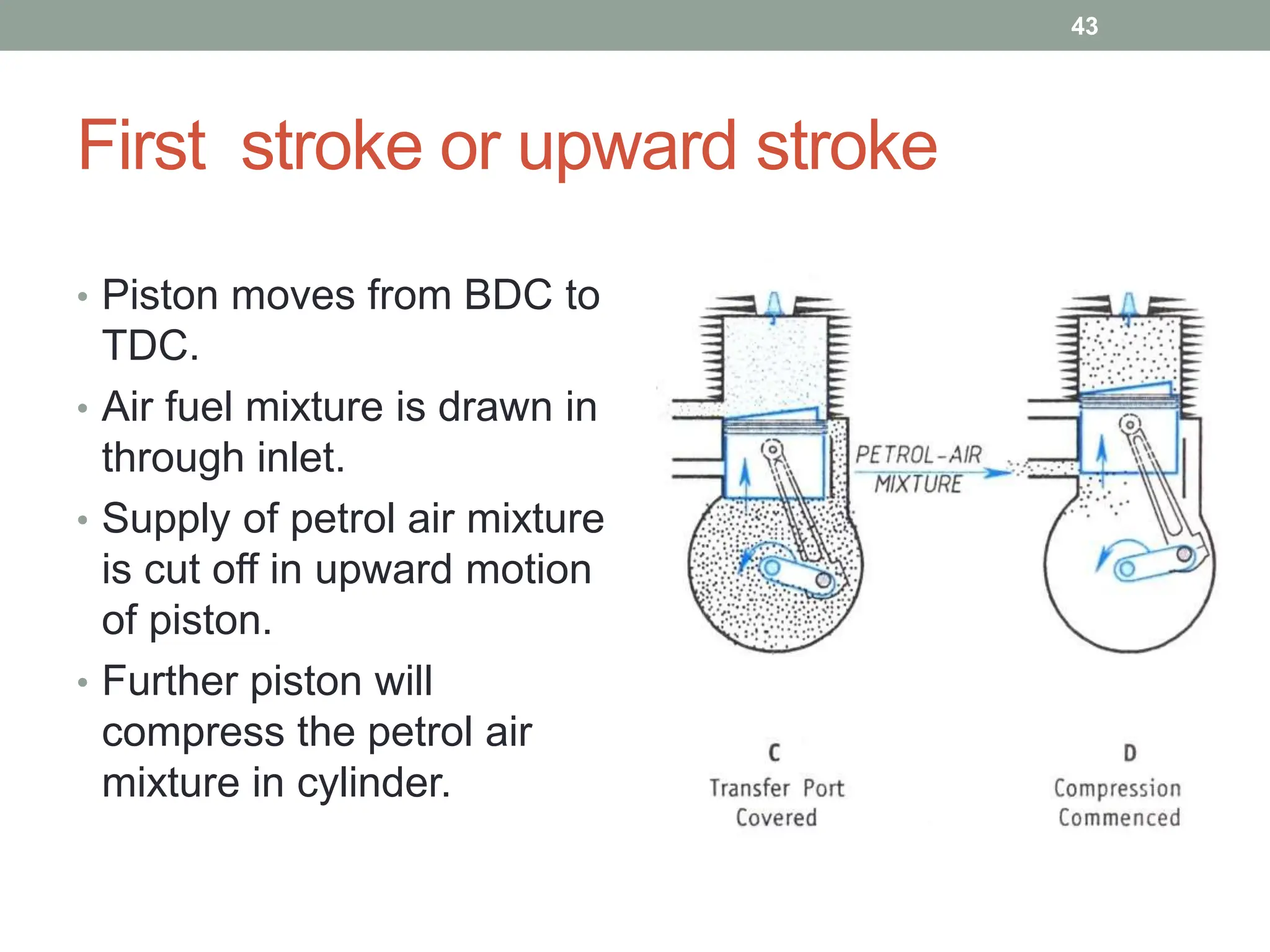
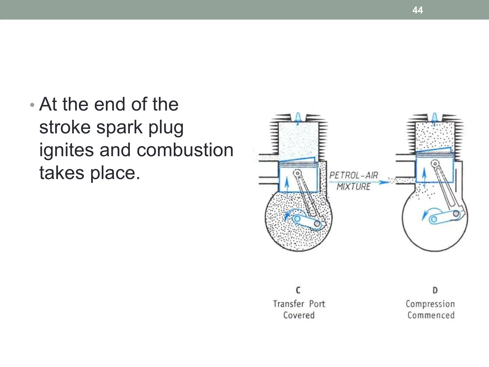
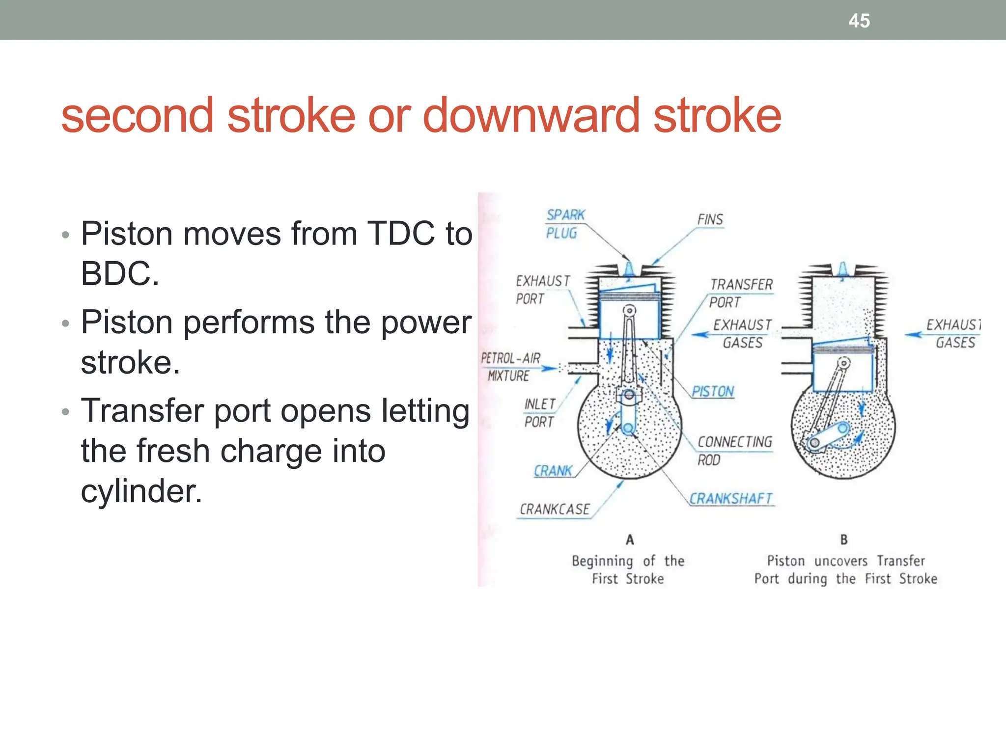


The document provides an overview of internal combustion engines (I.C. engines), detailing their classification based on fuel type, stroke count, ignition method, combustion cycle, cylinder arrangement, and cooling method. It further explains key components such as the cylinder, piston, connecting rod, and crankshaft, as well as the operational cycles of four-stroke and two-stroke engines. Additionally, it describes the specific processes of suction, compression, power, and exhaust strokes in petrol and diesel engines.


