Download to read offline

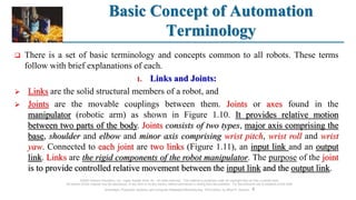
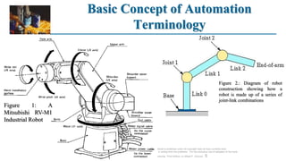
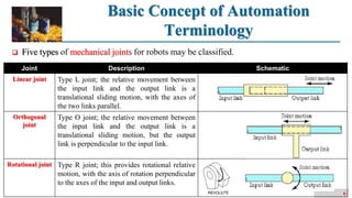
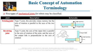
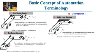
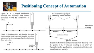
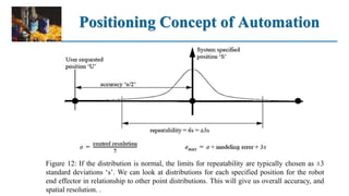
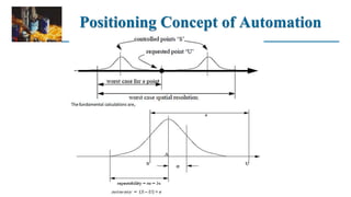
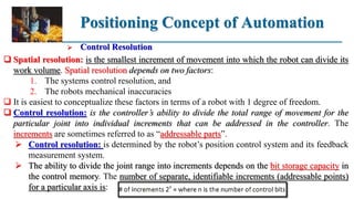
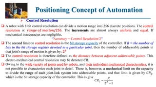
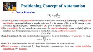
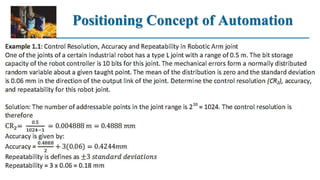
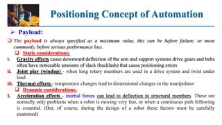
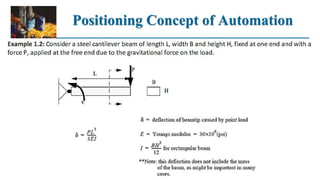
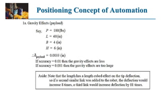
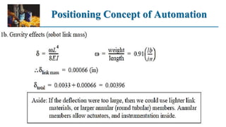
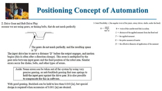
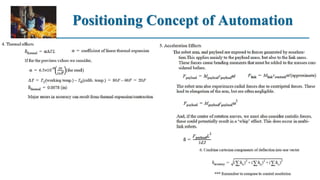


The document discusses basic concepts of automation including terminology like links, joints, degrees of freedom, tool center point, work envelope, speed, payload, repeatability, accuracy, settling time, control resolution, and coordinates. It explains different types of joints, orientation and position axes, and factors that influence a robot's accuracy and repeatability such as resolution, kinematic modeling errors, calibration errors, and random errors. The positioning concept of automation and how accuracy, repeatability, and control resolution are determined is also covered.


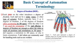
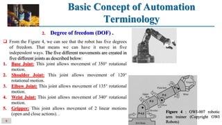
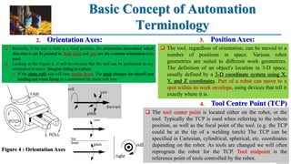
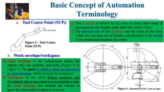
![Lecture_14b_-_Industrial_Robotics_-_Ch_8[1].pdf](https://cdn.slidesharecdn.com/ss_thumbnails/lecture14b-industrialrobotics-ch81-221025060929-cdd3144f-thumbnail.jpg?width=640&height=640&fit=bounds)