The project aims to design a smart stick for blind people using an Arduino microcontroller. The stick will use an ultrasonic sensor to detect obstacles and notify the user via a buzzer or LED. A group of 5 students will work on the project, which involves designing a circuit diagram, writing an algorithm, and testing the stick. The stick is expected to allow blind users to navigate more confidently by detecting obstacles and warning the user through sound or light signals.

![Introduction:
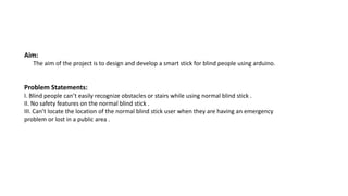
The main aim of the project is to enable the blind people navigate with
confidence. If their walking route becomes obstructed with other things,peoples
or related odds,then the buzzer warns.This stick is used for indoor as well as
outdoor use.so,the person can walk without any fear.This device will be best
solution to overcome difficulties of blind people[1]. Arduino and ultrasonic sensor
are the main components of the system which senses the obstacles and makes
buzz sound[2]. The audio sound will keep the user alert and considerably reduce
the accidents[3]. Distance information is conveyed to the user through vibratory
pattern. The drawback with this system is its cost which is not affordable for
people living in undeveloped areas,But it is easy to take for people who living in
developing areas[4].](https://image.slidesharecdn.com/modernstickforblindpeopleusingaruinomicrocontroller-230307090919-3a95db93/85/Modern-Stick-For-Blind-People-Using-Aruino-Microcontroller-pptx-4-320.jpg)
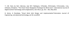
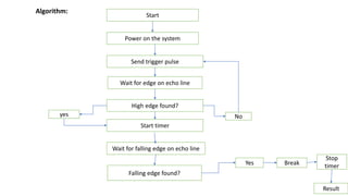
![Proposed Block Diagram:
Fig.1[5]
Obstacle Unit,
Ultrasonic Sensor
Arduino Uno
Power Supply Buzzer or LED](https://image.slidesharecdn.com/modernstickforblindpeopleusingaruinomicrocontroller-230307090919-3a95db93/85/Modern-Stick-For-Blind-People-Using-Aruino-Microcontroller-pptx-5-320.jpg)
![Components:
1.Arduino:
Arduino Uno is used to control all the sensors[2].](https://image.slidesharecdn.com/modernstickforblindpeopleusingaruinomicrocontroller-230307090919-3a95db93/85/Modern-Stick-For-Blind-People-Using-Aruino-Microcontroller-pptx-6-320.jpg)
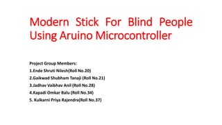
![2. Ultrasonic Sensor:
The HC-SR04 ultrasonic sensor uses SONAR to determine the distance of an object just
like the bats do. It offers excellent non-contact range detection with high accuracy and
stable readings in an easy-to-use package from 2 cm to 400 cm or 1” to 13 feet. The
operation is not affected by sunlight or black material[2].](https://image.slidesharecdn.com/modernstickforblindpeopleusingaruinomicrocontroller-230307090919-3a95db93/85/Modern-Stick-For-Blind-People-Using-Aruino-Microcontroller-pptx-7-320.jpg)
![3.Buzzer:
A buzzer is a small yet efficient component to ad sound features to our project/system. It is
very
small and compact 2-pin structure hence can be easily used on breadboard, Perf Board and
even
on PCB which makes this a widely used component in most electronic applications. This Buzzer
can be used by simply powering it using DC power supply ranging from 4V to 9V. A simple 9V
battery can also be used, but it is recommended to use a regulated +5V or +6V DC supply[2].](https://image.slidesharecdn.com/modernstickforblindpeopleusingaruinomicrocontroller-230307090919-3a95db93/85/Modern-Stick-For-Blind-People-Using-Aruino-Microcontroller-pptx-8-320.jpg)
![4.Light Emitting Diode(LED):
A light-emitting diode (LED) is a semiconductor light source that emits light when
current flows through it. Electrons in the semiconductor recombine with electron
holes, releasing energy in the form of photons. The color of the light (corresponding
to the energy of the photons) is determined by the energy required for electrons to
cross the band gap of the semiconductor[5].White light is obtained by using multiple
semiconductors or a layer of light-emitting phosphor on the semiconductor device[2].](https://image.slidesharecdn.com/modernstickforblindpeopleusingaruinomicrocontroller-230307090919-3a95db93/85/Modern-Stick-For-Blind-People-Using-Aruino-Microcontroller-pptx-9-320.jpg)
![5.Battery:
The complete board is powered by a 9V battery which is regulated to +5V using a 7805 Voltage
regulator. The Ultrasonic sensor is powered by 5V and the trigger and Echo pin is connected to
Arduino nano pin 3 and2[2].
6.Wires for connection.
7.Breadboard.](https://image.slidesharecdn.com/modernstickforblindpeopleusingaruinomicrocontroller-230307090919-3a95db93/85/Modern-Stick-For-Blind-People-Using-Aruino-Microcontroller-pptx-10-320.jpg)
![Proposed Circuit Diagram:
Fig.2[2]](https://image.slidesharecdn.com/modernstickforblindpeopleusingaruinomicrocontroller-230307090919-3a95db93/85/Modern-Stick-For-Blind-People-Using-Aruino-Microcontroller-pptx-11-320.jpg)
![Working:
The Smart Blind Stick scans the path in front of it with the help of an HC-SR04 Ultrasonic
sensor.Whenever the sensor detects any object in its path the buzzer starts beeping and
also at the same time the LED turns on.The blind person can hear the beeping of the
buzzer and manage to change the way. In this way, the person can easily find his way
without getting injured.This smart stick works in the same way as the Ultrasonic range
finder did.Once the circuit is ready for this Arduino mini-project tie the whole set-up to a
stick using zip ties[7].
Connections:
Attach the 5-volts and GND pins of the Arduino to the VCC and GND pins of the ultrasonic
sensor.Connect the TRIG and ECHO pins of the ultrasonic sensor with the digital-9 and
digital-10 pins of the Arduino.Join the positive and negative wire of the buzzer with the
digital-5 and GND pins of the Arduino.Attach the positive leg of the LED with the digital-6
pin of the Arduino and the negative leg of the LED with the GND pin of the Arduino
through a 220-ohm resistor.You can use a breadboard for making common connections.
Power the Arduino board using DC batteries[4]](https://image.slidesharecdn.com/modernstickforblindpeopleusingaruinomicrocontroller-230307090919-3a95db93/85/Modern-Stick-For-Blind-People-Using-Aruino-Microcontroller-pptx-13-320.jpg)
![Advantages:
1.Person can walk more confidently and without fear.
2.Auto detection of obstacles[6].
3.Simple to use[1].
In our work we tried to overcome some of disadvantages:
We designed stick to detect obstacles.The training of our product isnt as
expensive as training in other product. Our training is just description of stick
component and usage position..We achieved very fast response time in average
distance[8].
Objectives:
1.To study existing hardware for blind people.
2.To develop a hardware for blind people which helps to recognise obstacles.
3.To reduce the risk of injuries of the visually impaired person.](https://image.slidesharecdn.com/modernstickforblindpeopleusingaruinomicrocontroller-230307090919-3a95db93/85/Modern-Stick-For-Blind-People-Using-Aruino-Microcontroller-pptx-14-320.jpg)
![Expected outcomes:
1.To create a hardware which easily recognise of stackle or wall in front of blind people
2.To reduce the proportion of accident in blind people's life and maintain their
confidence.
Research motivation:
While surviving,we see many blind peoples around us who are not able to walk
confidently and without fear because of blindness.for them we have to design a
hardware which help them for wolking without fear and confidently.
Significance of project:
To prevent and reduce the risk of injuries and lost of the visually impaired person.
Scope of project:
Visual impaired person that having trouble to navigate[7].
g](https://image.slidesharecdn.com/modernstickforblindpeopleusingaruinomicrocontroller-230307090919-3a95db93/85/Modern-Stick-For-Blind-People-Using-Aruino-Microcontroller-pptx-15-320.jpg)