Download to read offline


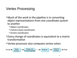
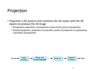
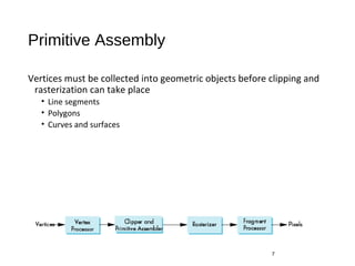

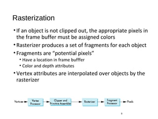
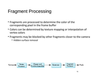
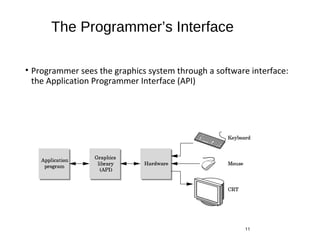


This document discusses different models and architectures for computer graphics rendering. It describes the graphics rendering pipeline which processes objects one at a time through steps like vertex processing, projection, clipping, rasterization and fragment processing to generate the final 2D image. It also discusses the application programmer interface (API) that allows programmers to specify 3D scenes through objects, materials, lights and view parameters to render on the graphics hardware.