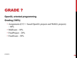
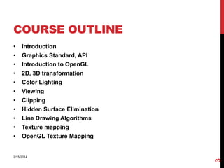
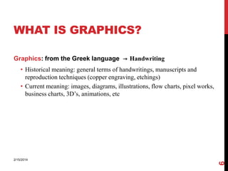
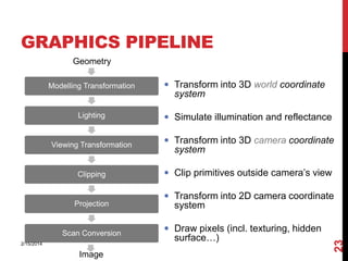
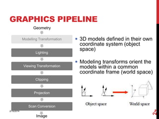
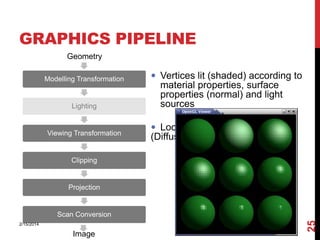
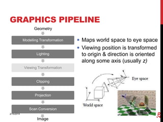
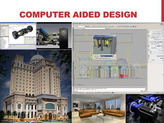
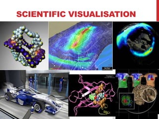
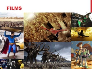
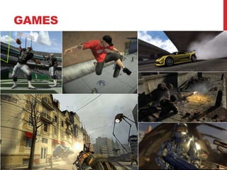
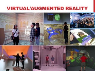
1

2/15/2014
GRADE ?
OpenGL oriented programming

Grading (100%)

2/15/2014

2

• Assignments (C/C++ based OpenGL projects and WebGL projects)
– 40%
• MidExam – 10%
• FinalProject – 20%
• FinalExam – 30%
COURSE OUTLINE
Introduction

•

Graphics Standard, API

•

Introduction to OpenGL

•

2D, 3D transformation

•

Color Lighting

•

Viewing

•

Clipping

•

Hidden Surface Elimination

•

Line Drawing Algorithms

•

Texture mapping

•

OpenGL Texture Mapping

2/15/2014

3

•
2/15/2014

4

JAVKHLAN.R
OVERVIEW
• What is Computer Graphics
• Basic graphics system
• History of Computer Graphics
• Graphics pipeline
• Application areas

2/15/2014

5

• Computer Graphics Programming course
WHAT IS GRAPHICS?
Graphics: from the Greek language → Handwriting

2/15/2014

6

• Historical meaning: general terms of handwritings, manuscripts and
reproduction techniques (copper engraving, etchings)
• Current meaning: images, diagrams, illustrations, flow charts, pixel works,
business charts, 3D’s, animations, etc
WHAT IS COMPUTER GRAPHICS?
The term computer graphics has been used in a broad sense to describe
"almost everything on computers that is not text or sound“
Typically, the term computer graphics refers to several different things:

2/15/2014

7

• the representation and manipulation of image data by a computer
• the various technologies used to create and manipulate images the images
so produced, and
• the sub-field of computer science which studies methods for digitally
synthesizing and manipulating visual content
RESEARCH FIELDS OF CG
Generative CG (1)
Design, storage and rendering of graphical models
• Object modeling based on basic graphic primitives
• Modeling of object behavior
• Rendering algorithm
• Animation
Image recognition (2)
Detection of information from images
• Recognition of lines, patterns and text
• Automated annotation of images
• Object reconstruction
Image processing (3)

Image
Description

(1)

(2)
Image

Manipulation of images
• Photoshop

8

(3)
2/15/2014
BASIC GRAPHICS SYSTEM

Output device
Input devices
Image formed in FB
INPUT DEVICES
1.Keyboard
2.Mouse
3.Trackball & Spaceball
4.Joysticks

5.Data Glove
6.Digitizer/Graphical Tablet
7.Image Scanners
8.Touch panels

2/15/2014

10

9.Light Pens
OUTPUT DEVICES
Video Display Devices
• Cathode Ray Tubes
• Vector scan/Random scan Display
• Raster scan Display
• color CRT monitors
• Flat panel Display
• Plasma panel Display
• LCD
• LED
Hard Copy Devices

2/15/2014

11

• printers
• Plotters
CONCEPTUAL FRAMEWORK FOR
INTERACTIVE GRAPHICS
Graphics library/package is intermediary between
application and display hardware (Graphics System)

2/15/2014

12

Application program maps application objects to views
(images) of those objects by calling on graphics library.
GRAPHICS DISPLAY HARDWARE
• Driven by display commands (move (x, y),
char(“A”) , line(x, y)…)
• Survives as “scalable vector graphics”

2/15/2014

 Raster (TV, bitmap) used in

displays and laser printers
 Driven by array of pixels (no semantics,
lowest form of representation)
 Note “jaggies” (aliasing errors) due to
sampling continuous primitives

13

Vector (calligraphic, stroke, etc)
HISTORY OF CG
Ivan Sutherland (1963) – SKETCHPAD

2/15/2014

14

• Using a light pen, key pad and monitor it allowed
users create accurate design drawings
DISPLAY HARDWARE
vector displays
• 1963 – modified oscilloscope
• 1974 – Evans and Sutherland Picture System
raster displays
• 1975 – Evans and Sutherland frame buffer
• 1980s – cheap frame buffers bit-mapped personal
computers
• 1990s – liquid-crystal displays laptops
• 2000s – micro-mirror projectors
digital cinema
other
• head-mounted displays
• autostereoscopic displays
RENDERING
1960s - the visibility problem

• Roberts (1963), Appel (1967) - hidden-line algorithms
• Warnock (1969), Watkins (1970) - hidden-surface algorithms
• Sutherland (1974) - visibility = sorting
1960s - the visibility problem

• Roberts (1963), Appel (1967) - hidden-line algorithms
• Warnock (1969), Watkins (1970) - hidden-surface algorithms
• Sutherland (1974) - visibility = sorting
1970s - raster graphics
•
•
•
•
•

Gouraud (1971) - diffuse lighting
Phong (1974) - specular lighting
Blinn (1974) - curved surfaces, texture
Catmull (1974) - Z-buffer hidden-surface algorithm
Crow (1977) - anti-aliasing
early 1980s - global illumination
• Whitted (1980) - ray tracing
• Goral, Torrance et al. (1984), Cohen (1985) - radiosity
• Kajiya (1986) - the rendering equation
early 1980s - global illumination

• Whitted (1980) - ray tracing
• Goral, Torrance et al. (1984), Cohen (1985) - radiosity
• Kajiya (1986) - the rendering equation
late 1980s - photorealism
• Cook (1984) - shade trees
• Perlin (1985) - shading languages
• Hanrahan and Lawson (1990) - RenderMan
early 1990s - non-photorealistic rendering
•
•
•
•

Drebin et al. (1988), Levoy (1988) - volume rendering
Haeberli (1990) - impressionistic paint programs
Salesin et al. (1994-) - automatic pen-and-ink illustration
Meier (1996) - painterly rendering
early 1990s - non-photorealistic rendering
•
•
•
•

Drebin et al. (1988), Levoy (1988) - volume rendering
Haeberli (1990) - impressionistic paint programs
Salesin et al. (1994-) - automatic pen-and-ink illustration
Meier (1996) - painterly rendering
GRAPHICS PIPELINE
Geometry
Modelling Transformation

 Transform into 3D world coordinate

system

Lighting

 Simulate illumination and reflectance

Viewing Transformation

 Transform into 3D camera coordinate

Clipping

 Clip primitives outside camera’s view

Scan Conversion
2/15/2014

Image

 Transform into 2D camera coordinate

system
 Draw pixels (incl. texturing, hidden

surface…)

23

Projection

system
GRAPHICS PIPELINE
Geometry
Modelling Transformation

Lighting

 3D models defined in their own

coordinate system (object
space)
 Modeling transforms orient the

Viewing Transformation

models within a common
coordinate frame (world space)

Clipping

Projection

2/15/2014

Image

24

Scan Conversion
GRAPHICS PIPELINE
Geometry
Modelling Transformation

Lighting

Viewing Transformation

 Vertices lit (shaded) according to

material properties, surface
properties (normal) and light
sources
 Local lighting model

(Diffuse, Ambient, etc.)

Clipping

Projection

2/15/2014

Image

25

Scan Conversion
GRAPHICS PIPELINE
Geometry
Modelling Transformation

 Maps world space to eye space
 Viewing position is transformed

Lighting

to origin & direction is oriented
along some axis (usually z)

Viewing Transformation

Clipping

Projection

2/15/2014

Image

26

Scan Conversion
GRAPHICS PIPELINE
Geometry
Modelling Transformation

Lighting

 Portions of the object
outside the view volume

(view frustum) are removed

Viewing Transformation

Clipping

Projection

2/15/2014

Image

27

Scan Conversion
GRAPHICS PIPELINE
Geometry
Modelling Transformation

Lighting

 The objects are projected to
the 2D image place (screen

space)

Viewing Transformation

Clipping

Projection

2/15/2014

Image

28

Scan Conversion
GRAPHICS PIPELINE
Geometry
Modelling Transformation

Lighting

Viewing Transformation

 Rasterizes objects into
pixels

 Interpolate values as we go
(color, depth, etc.)

Clipping

Projection

2/15/2014

Image

29

Scan Conversion
MODELING AND RENDERING
Modeling
•
•
•
•
•

Create models
Apply materials to models
Place models around scene
Place lights in scene
Place the camera

Rendering
• Take “picture” with camera

Point Light

Spot Light

Directional
Light
Ambient Light
CG VS. REAL

… to the streets of London

2/15/2014

31

From video game…
(Gran Turismo 5, PS)
SOME APPLICATIONS OF COMPUTER
GRAPHICS
Some of the application areas which make heavy use of computer
graphics are:

2/15/2014

32

• Computer aided design
• Scientific visualisation
• Films
• Games
• Virtual/Augmented Reality
NOTE: There are lots more and there is huge overlap between these
different areas
COMPUTER AIDED DESIGN
SCIENTIFIC VISUALISATION
FILMS
GAMES
VIRTUAL/AUGMENTED REALITY

Cgp lecture1 introduction

  • 1.
  • 2.
    GRADE ? OpenGL orientedprogramming Grading (100%) 2/15/2014 2 • Assignments (C/C++ based OpenGL projects and WebGL projects) – 40% • MidExam – 10% • FinalProject – 20% • FinalExam – 30%
  • 3.
    COURSE OUTLINE Introduction • Graphics Standard,API • Introduction to OpenGL • 2D, 3D transformation • Color Lighting • Viewing • Clipping • Hidden Surface Elimination • Line Drawing Algorithms • Texture mapping • OpenGL Texture Mapping 2/15/2014 3 •
  • 4.
  • 5.
    OVERVIEW • What isComputer Graphics • Basic graphics system • History of Computer Graphics • Graphics pipeline • Application areas 2/15/2014 5 • Computer Graphics Programming course
  • 6.
    WHAT IS GRAPHICS? Graphics:from the Greek language → Handwriting 2/15/2014 6 • Historical meaning: general terms of handwritings, manuscripts and reproduction techniques (copper engraving, etchings) • Current meaning: images, diagrams, illustrations, flow charts, pixel works, business charts, 3D’s, animations, etc
  • 7.
    WHAT IS COMPUTERGRAPHICS? The term computer graphics has been used in a broad sense to describe "almost everything on computers that is not text or sound“ Typically, the term computer graphics refers to several different things: 2/15/2014 7 • the representation and manipulation of image data by a computer • the various technologies used to create and manipulate images the images so produced, and • the sub-field of computer science which studies methods for digitally synthesizing and manipulating visual content
  • 8.
    RESEARCH FIELDS OFCG Generative CG (1) Design, storage and rendering of graphical models • Object modeling based on basic graphic primitives • Modeling of object behavior • Rendering algorithm • Animation Image recognition (2) Detection of information from images • Recognition of lines, patterns and text • Automated annotation of images • Object reconstruction Image processing (3) Image Description (1) (2) Image Manipulation of images • Photoshop 8 (3) 2/15/2014
  • 9.
    BASIC GRAPHICS SYSTEM Outputdevice Input devices Image formed in FB
  • 10.
    INPUT DEVICES 1.Keyboard 2.Mouse 3.Trackball &Spaceball 4.Joysticks 5.Data Glove 6.Digitizer/Graphical Tablet 7.Image Scanners 8.Touch panels 2/15/2014 10 9.Light Pens
  • 11.
    OUTPUT DEVICES Video DisplayDevices • Cathode Ray Tubes • Vector scan/Random scan Display • Raster scan Display • color CRT monitors • Flat panel Display • Plasma panel Display • LCD • LED Hard Copy Devices 2/15/2014 11 • printers • Plotters
  • 12.
    CONCEPTUAL FRAMEWORK FOR INTERACTIVEGRAPHICS Graphics library/package is intermediary between application and display hardware (Graphics System) 2/15/2014 12 Application program maps application objects to views (images) of those objects by calling on graphics library.
  • 13.
    GRAPHICS DISPLAY HARDWARE •Driven by display commands (move (x, y), char(“A”) , line(x, y)…) • Survives as “scalable vector graphics” 2/15/2014  Raster (TV, bitmap) used in displays and laser printers  Driven by array of pixels (no semantics, lowest form of representation)  Note “jaggies” (aliasing errors) due to sampling continuous primitives 13 Vector (calligraphic, stroke, etc)
  • 14.
    HISTORY OF CG IvanSutherland (1963) – SKETCHPAD 2/15/2014 14 • Using a light pen, key pad and monitor it allowed users create accurate design drawings
  • 15.
    DISPLAY HARDWARE vector displays •1963 – modified oscilloscope • 1974 – Evans and Sutherland Picture System raster displays • 1975 – Evans and Sutherland frame buffer • 1980s – cheap frame buffers bit-mapped personal computers • 1990s – liquid-crystal displays laptops • 2000s – micro-mirror projectors digital cinema other • head-mounted displays • autostereoscopic displays
  • 16.
    RENDERING 1960s - thevisibility problem • Roberts (1963), Appel (1967) - hidden-line algorithms • Warnock (1969), Watkins (1970) - hidden-surface algorithms • Sutherland (1974) - visibility = sorting
  • 17.
    1960s - thevisibility problem • Roberts (1963), Appel (1967) - hidden-line algorithms • Warnock (1969), Watkins (1970) - hidden-surface algorithms • Sutherland (1974) - visibility = sorting 1970s - raster graphics • • • • • Gouraud (1971) - diffuse lighting Phong (1974) - specular lighting Blinn (1974) - curved surfaces, texture Catmull (1974) - Z-buffer hidden-surface algorithm Crow (1977) - anti-aliasing
  • 18.
    1960s - thevisibility problem • Roberts (1963), Appel (1967) - hidden-line algorithms • Warnock (1969), Watkins (1970) - hidden-surface algorithms • Sutherland (1974) - visibility = sorting 1970s - raster graphics • • • • • Gouraud (1971) - diffuse lighting Phong (1974) - specular lighting Blinn (1974) - curved surfaces, texture Catmull (1974) - Z-buffer hidden-surface algorithm Crow (1977) - anti-aliasing
  • 19.
    early 1980s -global illumination • Whitted (1980) - ray tracing • Goral, Torrance et al. (1984), Cohen (1985) - radiosity • Kajiya (1986) - the rendering equation
  • 20.
    early 1980s -global illumination • Whitted (1980) - ray tracing • Goral, Torrance et al. (1984), Cohen (1985) - radiosity • Kajiya (1986) - the rendering equation late 1980s - photorealism • Cook (1984) - shade trees • Perlin (1985) - shading languages • Hanrahan and Lawson (1990) - RenderMan
  • 21.
    early 1990s -non-photorealistic rendering • • • • Drebin et al. (1988), Levoy (1988) - volume rendering Haeberli (1990) - impressionistic paint programs Salesin et al. (1994-) - automatic pen-and-ink illustration Meier (1996) - painterly rendering
  • 22.
    early 1990s -non-photorealistic rendering • • • • Drebin et al. (1988), Levoy (1988) - volume rendering Haeberli (1990) - impressionistic paint programs Salesin et al. (1994-) - automatic pen-and-ink illustration Meier (1996) - painterly rendering
  • 23.
    GRAPHICS PIPELINE Geometry Modelling Transformation Transform into 3D world coordinate system Lighting  Simulate illumination and reflectance Viewing Transformation  Transform into 3D camera coordinate Clipping  Clip primitives outside camera’s view Scan Conversion 2/15/2014 Image  Transform into 2D camera coordinate system  Draw pixels (incl. texturing, hidden surface…) 23 Projection system
  • 24.
    GRAPHICS PIPELINE Geometry Modelling Transformation Lighting 3D models defined in their own coordinate system (object space)  Modeling transforms orient the Viewing Transformation models within a common coordinate frame (world space) Clipping Projection 2/15/2014 Image 24 Scan Conversion
  • 25.
    GRAPHICS PIPELINE Geometry Modelling Transformation Lighting ViewingTransformation  Vertices lit (shaded) according to material properties, surface properties (normal) and light sources  Local lighting model (Diffuse, Ambient, etc.) Clipping Projection 2/15/2014 Image 25 Scan Conversion
  • 26.
    GRAPHICS PIPELINE Geometry Modelling Transformation Maps world space to eye space  Viewing position is transformed Lighting to origin & direction is oriented along some axis (usually z) Viewing Transformation Clipping Projection 2/15/2014 Image 26 Scan Conversion
  • 27.
    GRAPHICS PIPELINE Geometry Modelling Transformation Lighting Portions of the object outside the view volume (view frustum) are removed Viewing Transformation Clipping Projection 2/15/2014 Image 27 Scan Conversion
  • 28.
    GRAPHICS PIPELINE Geometry Modelling Transformation Lighting The objects are projected to the 2D image place (screen space) Viewing Transformation Clipping Projection 2/15/2014 Image 28 Scan Conversion
  • 29.
    GRAPHICS PIPELINE Geometry Modelling Transformation Lighting ViewingTransformation  Rasterizes objects into pixels  Interpolate values as we go (color, depth, etc.) Clipping Projection 2/15/2014 Image 29 Scan Conversion
  • 30.
    MODELING AND RENDERING Modeling • • • • • Createmodels Apply materials to models Place models around scene Place lights in scene Place the camera Rendering • Take “picture” with camera Point Light Spot Light Directional Light Ambient Light
  • 31.
    CG VS. REAL …to the streets of London 2/15/2014 31 From video game… (Gran Turismo 5, PS)
  • 32.
    SOME APPLICATIONS OFCOMPUTER GRAPHICS Some of the application areas which make heavy use of computer graphics are: 2/15/2014 32 • Computer aided design • Scientific visualisation • Films • Games • Virtual/Augmented Reality NOTE: There are lots more and there is huge overlap between these different areas
  • 33.
  • 34.
  • 35.
  • 36.
  • 37.

Editor's Notes

  • #12 The cathode ray tube (CRT) is a vacuum tube containing an electron gun (a source of electrons) and a fluorescent screen, with internal or external means to accelerate and deflect the electron beam, used to create images in the form of light emitted from the fluorescent screen. The image may represent electrical waveforms (oscilloscope), pictures (television, computer monitor), radar targets and others.