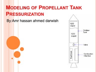
This document describes the modeling of propellant tank pressurization for hybrid rockets. The major advantage of modeling tank pressurization is that it is essential for predicting rocket performance, especially for hybrid rockets that use self-pressurizing oxidizers where thrust depends on tank pressure. The objective is to develop a model that can be incorporated into rocket design programs. The model assumes the propellant is a real gas, two-phase homogeneous mixture and analyzes governing equations using the Soave-Benedict-Webb Rubin and Peng-Robinson equations of state. Results show good agreement between measured and predicted ullage pressures and mass variations over time, validating the model.
Refractory Product Line | Optimum Solutions for Cement PlantsRefratechnik Group
To meet the globally increasing demand for cement, energy saving firing systems with high specific output have been developed in the industrialized countries and introduced throughout the world. One of the primary results of these developments is the precalciner kiln with a short rotary kiln
section.
As each kiln is unique, appropriate refractories are a major factor in terms of service life.
Steel structure: Bolted Connection chapter
A bolt is a metal pin with a head formed at one end and shank threaded at the other in order to
receive a nut. On the basis of load transfer in the connection bolts are classified as:
(a) Bearing Type
(b) Friction Grip Type
There are two types of bearing type bolts, namely,
(i) Unfinished or Black Bolts.
(ii) Finished or Turned Bolts.
The shanks of black bolts are unfinished, i.e., rough as obtained at the time of rolling, while
turned bolts are obtained by turning hexagonal shank to circular shape. The bolt hole diameter is
only 1.5 mm larger than that of the shank in case of turned bolt. These bolts are used in special jobs
like connecting machine parts subject to dynamic loadings. For black bolts, diameter of bolt hole is
larger and are used in most of the work. A black bolt is represented as M16, M20, etc. which means
black bolt of nominal diameter 16 mm, black bolt of nominal diameter 20 mm, etc.
-DESIGN STRENGTH OF BEARING BOLTS
-DESIGN STRENGTH OF HSFG BOLTS IN SHEAR (Vdsf)
-PRINCIPLES TO BE OBSERVED IN THE DESIGN
A conveyor belt is the carrying medium of a belt conveyor system, one of the many types of conveyor systems available today.
Belt conveyors can be used to transport products in a straight line or through changes in elevation or direction.
This presentation is intended for year-2 BEng/MEng Civil and Structural Engineering Students. The main purpose is to present how characterise wind loading on simple building structures according to Eurocode 1
This software is designed for Marine Bunker Surveyors to minimize time in bunker quantification following API-MPMS guidelines. It also contains some other conversion tools which are really important to calculate the fuel characteristics like Shell CCAI, BP CII, Net and Gross Specific Energy, Injection, Temperature based on measured viscosity, density conversion tools and much more.
CargoSurveyor: toolbox for marine cargo surveyorsRon Mooring
CargoSurveyor is the ultimate iOS app for marine cargo surveyors. It contains a complete set of tools to carry out full cargo surveys on board oil / chemical tankers and bunker surveys. It contains all you need to produce smart accurate ullage reports, bunker reports, transfer records, VEF reports, letters of protest and much more. See also mooringmarineconsultancy.wordpress.com.
Download it on iTunes: http://bit.ly/1A6X1Wy
THERMAL INVESTIGATION ON PROPELANT TANK MATERIAL BY USING FEM APPROACHIjripublishers Ijri
Rocket propellant tanks are pressure vessels where liquid fuels are stored prior to use. They have to store the propellant;
propellant combinations are used in rocket engines where the propellants spontaneously ignite when they come into
contact with each other. The two propellant components usually consist of a fuel (Unsymmetrical dimethyl hydrazine
(UDMH)) and an oxidizer (nitrogen tetroxide (N2O4)).
Fuel System Library is a Modelica library targeting the design and verification of fuel systems on civil and military aircraft. The library is designed to analyze and verify system behavior during various dynamic operating modes and flight conditions.
The Engine Dynamics Library is used for combustion engine systems modeling, simulation and analysis, including engine to intake/exhaust flow paths, intercoolers, turbochargers, and EGR-loops. Pressure and thermal dynamics of the complete air and exhaust gas exchange are explicitly modeled. Several turbocharger and EGR configurations can be modeled, including variable geometry turbine designs. The library is well suited for creating models used in transient engine response and related engine control.
Overview of Reservoir Simulation by Prem Dayal Saini
Reservoir simulation is the study of how fluids flow in a hydrocarbon reservoir when put under production conditions. The purpose is usually to predict the behavior of a reservoir to different production scenarios, or to increase the understanding of its geological properties by comparing known behavior to a simulation using different geological representations.
Comparative Study of ECONOMISER Using the CFD Analysis IJMER
This paper presents a simulation of the economizer zone, which allowsstudying the flow
patterns developed in the fluid, while it flows along the length of the economizer. The past failure
details revelsthat erosion is more in U-bend areas of Economizer Unit because of increase in flue gas
velocity near these bends. But it isobserved that the velocity of flue gases surprisingly increases near
the lower bends as compared to upper ones. The model issolved using conventional CFD techniques by
FLUENT software. In which the individual tubes are treated as sub-gridfeatures. A geometrical model
is used to describe the multiplicity of heat-exchanging structures and the interconnectionsamong them.
The Computational Fluid Dynamics (CFD) approach is utilised for the creation of a three-dimensional
modelof the economizer coil of single column tube. With equilibrium assumption applied for
description of the system chemistry. The flue gastemperature, pressure and velocity field of fluid flow
within an economizer tube using the actual bounda
ammonia water (NH3-H2o) diffusion vapor absorption refrigeration systemJagannath1234
1.Vapor absorption refrigeration system based on ammonia-water is one of the oldest refrigeration systems.
2.An absorption refrigeration system uses a heat source (e.g., geothermal energy, solar energy, and waste heat from steam plants, and even natural gas when it is at a relatively low price.) to provide the energy needed for the cooling process.
3.Quite similar to a vapor compression system.
4.The compressor is replaced by a generator and absorber.
5.Ammonia is used as a refrigerant i.e. R-717 and Water as an absorber.
6.Condensation, expansion and evaporation processes are the same as the VCR system.
Development of Dynamic Models for a Reactive Packed Distillation ColumnCSCJournals
This work has been carried out to develop dynamic models for a reactive packed distillation column using the production of ethyl acetate as the case study. The experimental setup for the production of ethyl acetate was a pilot scale packed column divided into condenser, rectification, acetic acid feed, reaction, ethanol feed, stripping and reboiler sections. The reaction section was filled with Amberlyst 15 catalyst while the rectification and the stripping sections were both filled raschig rings. The theoretical models for each of the sections of the column were developed from first principles and solved with the aid of MATLAB R2011a. Comparisons were made between the experimental and theoretical results by calculating the percentage residuals for the top and bottom segment temperatures of the column. The results obtained showed that there were good agreements between the experimental and theoretical top and bottom segment temperatures because the calculated percentage residuals were small. Therefore, the developed dynamic models can be used to represent the reactive packed distillation column.
Understanding and Predicting CO2 Properties for CCS Transport, Richard Graham, University of Nottingham. Presented at CO2 Properties and EoS for Pipeline Engineering, 11th November 2014
High Velocity Oxygen Fuel Nozzle Spray CFD ANALYSISbusiness info
Uncover the secrets of HVOF nozzle spray with CFD analysis. Explore internal flow, particle behavior, and optimize coating formation for superior results.
Fuel System Library is a Modelica library targeting the design and verification of fuel systems on civil and military aircraft. The library is designed to analyze and verify the system behavior during various dynamic operating modes and flight conditions.
Aircraft are characterized by large variations in acceleration and orientation. The Fuel System Library provides simulation results accounting for these effects on fuel-air mixtures and includes full support of bidirectional flow.
CFD Analysis on the Effect of Injection Timing for Diesel Combustion and Emis...IJERA Editor
This paper describes the effect of injection timing in diesel combustion. Ansys Fluent a computational fluid dynamics tool is used to study the combustion of diesel with three different injection timing. The fuel is injected before TDC, at TDC and after TDC. The parameters such as temperature, pressure, velocity, density, soot and NOx emission are compared. The specie transport model is used for modelling the combustion. Standard k-e (2 equ) is used for modelling the turbulence. The analysis is carried out by only considering the compression and expansion strokes. The pressure reaches the maximum when the fuel is injected before TDC and the maximum temperature is when injected at TDC. The NOx emission is less when the fuel is injected at TDC and the soot formation is when fuel injected before TDC.
3. SELF PRESSURIZED SYSTEMS
The advantages:
•Simple design with low parts count
•Inexpensive vehicle production
•Selectable tank pressures ranging up to
7Mpa
•Very few failure modes leading to superior
reliability
5. What is the major advantage of
modeling the Propellant tank
pressurization ?
Propellant tank pressurization is an
essential element of the prediction of
rocket performance. This is the case
even more so for hybrid rockets that use
a self-pressurizing oxidizer because the
thrust produced by the motor is
dependent on oxidizer tank pressure.
6. What is the Objective ?
Developing a model of a propellant
feed system that can be readily
incorporated into a rocket design
computer program. The model
developed is general and should
work well for propellant tanks that are
pressure fed with an inert gas and
also for self-pressurizing systems.
7. THE MODELING ANALYSIS
Assumptions
• Open system
• Real gas
• Two-phase (liquid-vapor) homogenous Nitrous
oxide
• The saturation layer is a thin layer
• Regular geometry shape of storage Tank
(cylinder shape)
• Frictionless flow in the tank
• Tank is in vertical position
• No chemical reactions
• No mechanical work
• Neglect change in potential energy
13. EVALUATING THE RATE OF MASSES
The rate of condensed vapor
The rate of evaporated liquid
The rate of change of gas mass Equation
The mass flow rate through the propellant
Feed system
14. The rate of change of Liquid mass Equation
EVALUATING THE RATE OF MASSES
15. EVALUATING THE RATE OF VOLUME CHANGE
The rate of change of bulk Liquid
volume:-
The rate of change of gas volume
16. HEAT TRANSFER
During the period of time when liquid is being expelled from the tank,
vaporization takes place at the liquid -vapor mixture interface or possibly
within the bulk liquid in the form of boiling
The free convection heat transfer between liquid and liquid
surface layer is
17. THE SOLUTION METHODOLOGY
Initial condition: The capacity of the oxidizer tank is 0.0354 m^3
with Tmperature surround the tank and mass are well known. The injector
area is 0.0001219352 m^2 in this model.
Calculate the saturation pressure from the surround temperature
and use The Soave-Benedict-Webb Rubin Equation of State to
get the density of gas and Liquid then evaluate the mass of liquid
and vapor from mass balanced equation .
a) Integrate numerically with time using the modified Euler method
𝑇𝐿 , 𝑇𝑇𝐺 , 𝑉𝑇𝐺 , 𝑉𝐿 , 𝑚 𝐿 and 𝑚 𝑇𝐺 to obtain 𝑇𝐿, 𝑇𝑇𝐺 ,𝑃𝑇𝐺 ,𝑉𝑇𝐺 , 𝑉𝐿, 𝑚 𝑇𝐺 , 𝑚 𝐿
Assume initially 𝜌𝐿 , 𝑃𝑇𝐺 and 𝜌 𝑇𝐺 are all set to be zero.
29. CONCLUSION
•A computer program of a propellant tank pressurization system
has been developed.
• This model is used to predict the self-pressurizing oxidizer
system of a moderate size hybrid rocket.
• The model does not assume thermo or phase equilibrium
(although the liquid surface is set equal to the saturated vapor
temperature) and is applicable to propellants that exhibit real-
fluid behavior.
• The results obtained are in good agreement with the published
and experimental data
30. REFERENCES
•M. Arif Karabeyoglu ," Modeling of Propellant Tank Pressurization",AIAA 2005-3549, 41th AIAA/ASME/ASEE
Joint Propulsion Conference, Tucson, Az, July 2005.
•V.A. Zakirov, L. Li ," 1-D, Homogenous Liquefied Gas Self –Pressurization Model", Tsinghua University, Beijing,
P.R. China, European conference Aerospace sciences (EUCASS).
•.Claus K. Zéberg-Mikkelsen," Viscosity Study of Hydrocarbon Fluids at Reservoir Conditions Modeling and
Measurements ", Department of Chemical Engineering, June 2001.
•Alok Majumdar and Todd Steadman," Numerical Modeling of Pressurization of a Propellant Tank ", Sverdrup
Technology, Huntsville, AI.
•Don W.Green and Robert H.Perry ,Perry's Chemical Engineers' Handbook, 8thEd, McGraw-Hill , Inc.,New York
,NY,2008.
•Rick Newlands," The physics of Nitrous Oxide", aspirespace, 2006.
•http://www.tsinghua.edu.cn/docsn/lxx/mainpage/a/Web/index.htm
•Margaret Mary Fernandez," Propellant Tank Pressurization Modeling for a Hybrid Rocket", Department of
Mechanical Engineering,Kate Gleason College of Engineering,Rochester Institute of Technology,Rochester, NY
14623, August 2009.
•Zakia Nasri and Housam Binous," Applications of the Peng-Robinson Equation of State using MATLAB",
National Institute of Applied Sciences and Technology.
•Matías A. Monsalvo," Phase Behavior and Viscosity Modeling of Refrigerant-Lubricant Mixtures", Ph. D. Thesis,
Technical University of Denmark, Center for Phase Equilibrium and Separation Process.