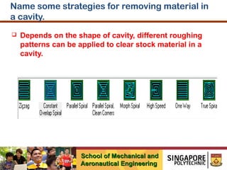
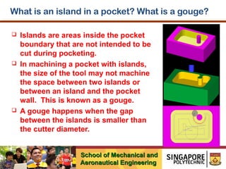
The document discusses Computer Aided Machining (CAM) and CNC milling. It provides information on:
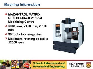
- The MAZAKTROL MATRIX NEXUS 410A-II Vertical Machining Centre machine, including its dimensions and specifications.
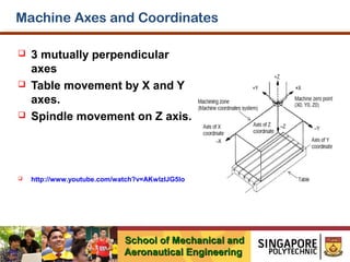
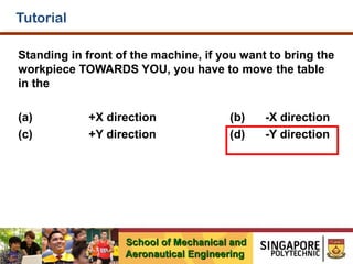
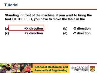
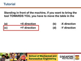
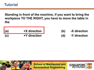
- The machine axes and coordinates system, including the three mutually perpendicular axes of X, Y, and Z.
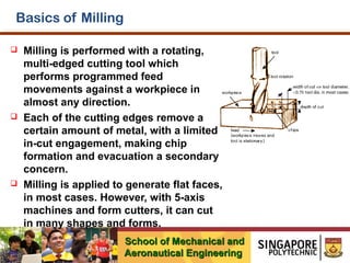
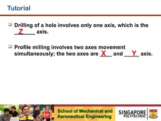
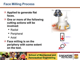
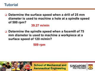
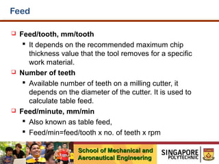
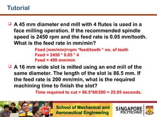
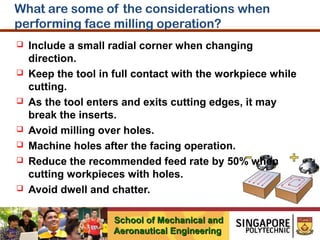
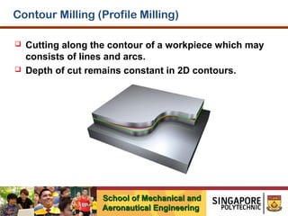
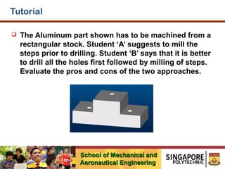
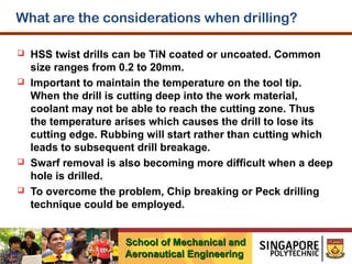
- The basics of milling, including that it involves a rotating cutting tool that removes metal in programmed movements.
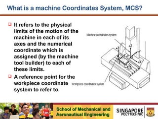
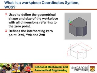
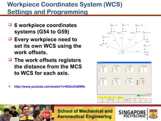
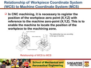
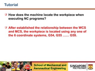
- The relationship between the machine coordinates system (MCS) and workpiece coordinates system (WCS), which defines the position of the workpiece for machining.
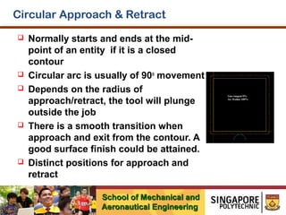
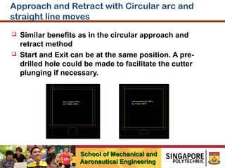
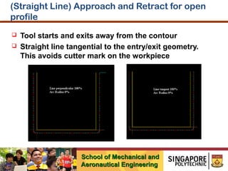
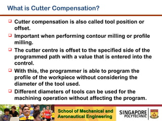
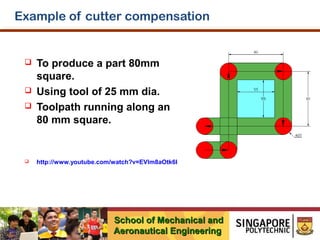
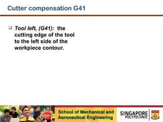
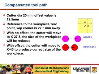
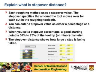
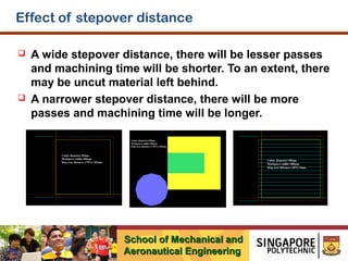
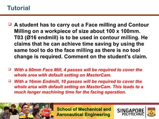
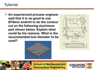
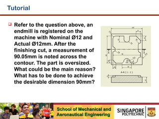
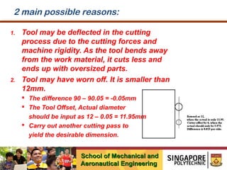
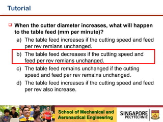
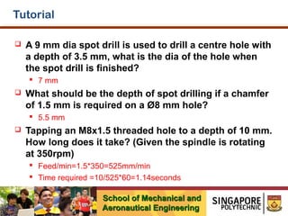
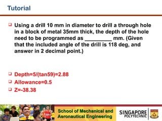
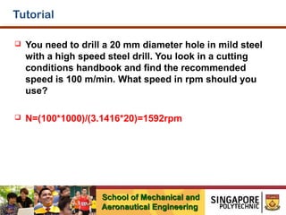
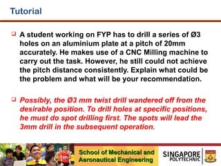
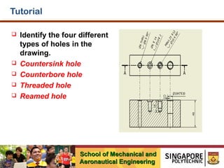
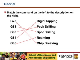
- Various tutorials and examples that explain concepts like cutter compensation,
This document provides information about various machining processes and machine tools. It describes machining as a metal removing process using machine tools and cutting tools. Lathe machines are commonly used to produce cylindrical surfaces and other operations like turning, drilling, boring, etc. Other machine tools discussed include milling machines, drilling machines, grinding machines, shaping machines, and planning machines. The document provides detailed descriptions of various operations that can be performed on these machines.
Dokumen tersebut memberikan pengenalan mengenai kikir, alat tangan yang digunakan untuk memotong dan mengikir logam. Ia menjelaskan jenis, bentuk, gigi, dan fungsi berbagai jenis kikir serta cara penggunaan dan penjagaan kikir yang betul. Jenis kikir yang disebutkan termasuk kikir pipih tirus, kikir bulat, kikir segiempat sama, kikir segitiga, dan kikir pipih nipis. Gaya dan te
The document discusses the history and components of lathe machines. It describes how lathe machines originated in 1794 in England and have since evolved. The key components of a lathe machine are then outlined, including the headstock, tailstock, bed, carriage, and feeding mechanism. Different types of lathe machines are also categorized.
Dokumen tersebut membahas tentang jenis-jenis mesin larik, termasuk mesin larik jentera (mesin bangku, mesin larik piawai, mesin toolroom, mesin gap-bed) dan mesin larik pengeluaran (mesin larik turret pelana, mesin kapstan, mesin automatik, mesin khusus, mesin NC dan CNC). Dokumen tersebut juga menjelaskan bagian-bagian mesin larik piawai dan kaedah-kaedah memegang
The document summarizes the main parts and specifications of a slotting machine. A slotting machine has a vertical ram and rotary table that allows for vertical cutting movement. The main parts include a base, column, table, and ram. The ram moves vertically to perform the cutting, guided by the column. Typical specifications for a 300mm stroke slotter include a 300mm maximum stroke, 450mm height between table and head, and dimensions for the table, bed, and overall machine. It is belt driven and requires 2HP power.
The document discusses shapers and planers, which are reciprocating machines that produce flat surfaces using single-point cutting tools. It describes the main parts of shapers and planers and compares their key differences. Shapers have a reciprocating ram that holds the stationary cutting tool, while planers keep the tool stationary and reciprocate the workpiece. Shapers are lighter, take up less space, use a single tool, and are less accurate than planers, making them better for small batch jobs. Planers are heavier, can use multiple tools simultaneously, achieve higher accuracy, and are more suitable for mass production of large workpieces.
1. Mesin pengisar digunakan untuk mengisar permukaan benda kerja dengan mata alat yang berputar.
2. Ia mampu mengisar permukaan rata, melubang, dan membuat alur dengan ketepatan tinggi.
3. Terdapat beberapa jenis mesin pengisar seperti mesin pengisar turus berlutut dan mesin pengisar pengeluaran untuk menghasilkan bahagian secara bermasal.
This document provides an overview of the main components and controls of a Takisawa TC-2 CNC lathe machine. It describes the power source, control box, NC equipment, control panel, main breaker, CRT unit, door, chuck, turret, tailstock, chuck pedal, operator's control panel, and optional components. It also outlines the functions of controls like axis references, feed direction selection, memory write switch, spindle speeds, tool selector, spindle rotation, and mode selector. The instructor is Shuhairi Hj Mohd. Samsudin from the Mechanical Engineering Department.
This document provides information about numerical control (NC) and computer numerical control (CNC) systems. It discusses the basic components and types of NC systems, as well as differences between conventional NC and CNC. Programming methods like incremental vs absolute positioning and point-to-point vs continuous path machining are summarized. Common machine tools used with CNC like lathes and milling machines are described along with their basic axes of motion. Interpolation types including linear and circular are also covered at a high level. The document serves as a lab sheet outlining key concepts for a CNC laboratory course.
Laporan ini membahas tentang workshop pengukuran benang skru. Workshop bertujuan untuk mengajarkan cara mengukur diameter utama, diameter minor, dan diameter efektif benang skru dengan tepat menggunakan alat ukur seperti mikrometer dan pembayang optik. Peserta juga mempelajari unsur-unsur penting benang skru dan cara mengukurnya.
The document provides information on operating and programming a CNC lathe. It includes warnings and cautions for safe operation, machine start and zero procedures, specifications for the machine, descriptions of common G-codes and M-codes used in programs, and examples of G71 and G72 stock removal cycles and a G75 grooving cycle. Safety is emphasized, with warnings to always wear protective equipment, properly clamp workpieces, and follow manufacturer guidelines. Programming and operation details are outlined to correctly home the machine, set work offsets, run simulations, and execute programs.
Centre lathe, constructional features, specification, operations – taper turning methods, thread
cutting methods, special attachments, machining time and power estimation. Capstan and turret
lathes- tool layout – automatic lathes: semi automatic – single spindle : Swiss type, automatic
screw type – multi spindle:
The document discusses the lathe machine tool. It describes the main parts of a lathe including the bed, headstock, spindle, tailstock, carriage and tooling. It explains the different types of lathes such as engine lathes, bench lathes, and special purpose lathes. It also outlines various operations that can be performed on a lathe like turning, facing, threading and drilling.
This document provides an overview of metal cutting processes on a center lathe. It discusses [1] the basic components and operation of a center lathe, [2] the types of single-point cutting tools used, [3] the theory behind metal cutting, and [4] important factors that influence tool life and cutting performance such as tool angles, cutting speed, feed, and use of cutting fluids. Safety procedures are also emphasized.
Gears are used to transmit power and motion between parallel or non-parallel shafts. Common types of gears include spur gears, helical gears, bevel gears, worm gears, and rack and pinion gears. Gears can be used to change the direction, speed, or ratio of rotation. Gear cutting methods include gear shaping, gear planing, and gear hobbing. Gear shaping involves reciprocating and rotating motions to cut gear teeth into a blank. Bevel gears connect shafts at any angle and resemble conical spur gears. They have many applications in machines.
Milling cutters are cutting tools used to remove material from workpieces in milling machines. They have cutting edges and flutes to remove chips of material. Common milling cutter types include end mills, face mills, and inserted tooth cutters. Milling cutters come in various geometries and are made of materials like high-speed steel or carbide depending on the application. Cutting parameters like spindle speed, feed rate, depth of cut, and surface cutting speed determine how efficiently a milling cutter removes material from a workpiece.
CNC Programming for Begainer.
1.Easy Mehtod.
2.Complete Theoritical Knowledge.
3.Motion and coordinate system for NC machine.
4.Axes convention of VMC & HMC.
5.How to make Part Programming.
6.Coordinates System.
7.Programming Format.
8.List of G Codes And M Codes.
9.How to Use of Above Codes In Programme.
10.Reference Point and Return of Machine.
This document contains engineering drawings and specifications for parts of a hydraulic forging machine. It includes 18 individual part drawings with dimensions and tolerances, labeled with part numbers. It also includes an assembly drawing with a parts list identifying each part and its quantity in the overall assembly. The drawings are for a hydraulic forging machine being designed and manufactured by Modern Academy for Engineering & Technology.
The document provides information on profile milling and contains 6 examples of CNC part programs for milling various components. The programs use G-code commands like G00, G01, G02, G03 as well as M-codes to perform operations like tool changes, spindle control and returning to reference points. Subprograms are used to repeat machining operations through the use of M98 calls and parameters.
The document contains 16 questions asking to write NC programs for various components. The questions cover topics like interpreting an NC program block by block, writing manual and APT programs for milling and turning operations, writing subroutines, and selecting cutting parameters like spindle speed and feed rates. Programs are to be written for operations like facing, roughing, finishing and drilling on materials like aluminum, steel and copper alloys. Dimensions and figures of the components are provided along with relevant cutting data.
This document provides information about CNC milling. It discusses learning outcomes, introduces milling processes and classifications. It describes the theory of CNC milling machines, including their characteristics, geometry, coordinate systems, zero and reference points, and programming structure. It also covers cutting values, clamping devices, and lists G-codes and M-functions.
CNC programming basics include:
1) Programs consist of a start, blocks of NC code, and an end. Blocks contain line numbers and commands like G01 for linear interpolation.
2) Absolute and incremental coordinate systems are used. Absolute defines positions from a fixed zero point, while incremental uses changes from the prior position.
3) G and M commands like G01 for linear moves or M03 to turn the spindle on are self-holding and remain active until deactivated explicitly. Reference points define the machine, tool, and workpiece coordinates.
This document provides an overview of basic CNC milling machine programming for FANUC controls. It covers topics such as general and machine coordinate systems, work coordinate systems, work datum setting, basic G and M codes, tool length compensation, cutter radius compensation, and programming examples for simple shapes. The examples demonstrate absolute and incremental programming, work offsets, tool calls, and the use of subprograms.
The document discusses various topics related to manufacturing processes including conventional and non-conventional machining processes, CNC machining, cutting speeds, feeds, tool offsets, programming codes and functions. It provides information on different machine tools, machining centers, transducers and controllers used in manufacturing. Cutting speed and feed rate tables are included for a variety of materials.
Here are the pros and cons of the two approaches:
Student A (mill steps first):
Pros: No risk of cutter hitting the holes during milling operation.
Cons: Drilling operation after milling may not be accurate due to possible deformation from milling. Chips from milling can enter holes and cause damage.
Student B (drill holes first):
Pros: Drilling operation will be more accurate as stock is intact. No risk of cutter or chips entering holes.
Cons: During milling, there is a risk of cutter hitting the holes if not planned properly. More careful machining is required.
Overall, Student B's approach of drilling holes first followed by
Broaching is a process of metal cutting. It is about operation in one pass. The tool is broaches and has several cutting edges. In next presentation will be explain type of tools, procedures of treatment, methods of treatment and others. The machine used for this treatments is broaching machine and the thesis provides a systematic model of vertical broaching machines.
This document provides an introduction to CNC milling. It begins by defining NC and CNC, explaining that CNC refers to a computer connected to an NC machine to increase versatility. It then discusses the basic components of an NC system, including the program of instructions, control unit, and machine tool. The document outlines different milling processes like face milling and end milling. It also explains machine coordinate systems and CAD/CAM software integration. Advantages of CNC include increased productivity and accuracy while limitations include high costs.
Welcome to International Journal of Engineering Research and Development (IJERD)IJERD Editor
call for paper 2012, hard copy of journal, research paper publishing, where to publish research paper,
journal publishing, how to publish research paper, Call For research paper, international journal, publishing a paper, IJERD, journal of science and technology, how to get a research paper published, publishing a paper, publishing of journal, publishing of research paper, reserach and review articles, IJERD Journal, How to publish your research paper, publish research paper, open access engineering journal, Engineering journal, Mathemetics journal, Physics journal, Chemistry journal, Computer Engineering, Computer Science journal, how to submit your paper, peer reviw journal, indexed journal, reserach and review articles, engineering journal, www.ijerd.com, research journals
The document discusses machining processes and lathe operations. It introduces machining as a process where a sharp cutting tool removes material from a rotating workpiece to achieve the desired shape. It then describes various machine tools used for machining like lathe, milling machine, drilling machine, and shaping machine. The majority of the document focuses on lathe components, operations that can be performed on a lathe like turning, facing, grooving etc. It also discusses important lathe parameters like cutting speed, feed, depth of cut. Finally, it provides an overview of CNC lathe and common G-codes and M-codes used.
This document provides information about shaping, planning, and slotting operations. It discusses the differences between these processes and the machines used. Shaping and slotting involve reciprocating the tool while feeding the workpiece, while planning involves reciprocating the workpiece and feeding the tool. Examples of shaping machines include horizontal and vertical shapers. Key parameters that affect machining include cutting speed, feed, depth of cut, and material removal rate. Example calculations are provided to determine machining time and cost for specific shaping operations.
Experimental investigation of ohns surface property and process parameter on ...ila vamsi krishna
This document discusses optimization of CNC milling operations. It investigates machining performance using different cutting speeds, feeds, and depths of cut with side and face milling cutters. Surface roughness was evaluated using Taguchi design of experiments and analysis of variance. The Taguchi method was used to formulate the experimental design and optimize milling parameters like speed, feed, and depth of cut. Analysis of variance and signal-to-noise ratios were used to study performance characteristics in milling operations.
The document discusses various aspects of shapers, planers, and slotters. It describes:
1) Shapers and planers use a single-point cutting tool in a straight-line motion to generate flat surfaces on workpieces, with intermittent feed between strokes on shapers.
2) Shapers use a quick return mechanism to rapidly return the cutting tool, with cutting speed varying over the stroke.
3) Slotters are essentially vertical shapers used to machine keyways and other non-flat surfaces.
4) Hydraulic shapers provide more constant cutting speed over the stroke compared to mechanical shapers.
This document provides instructions for students in the Mechanical Engineering Department's Machining and Machine Tools lab (ME692) at JIS College of Engineering. It outlines general information, safety rules, and procedures for 6 experiments to be performed on lathes and milling machines. The experiments include studying tool geometry, spur gear cutting, measuring cutting forces, and converting a circular rod to a square rod through shaping. Students are instructed to properly set up equipment, select cutting parameters, and take safety precautions to safely complete the machining operations and experiments.
IRJET- Design of Angular Way Drilling MachineIRJET Journal
This document describes the design of an angular way drilling machine. It includes 3 key points:
1) The machine allows for drilling holes at any angle between 0 and 90 degrees, providing more flexibility than traditional vertical drilling machines. It has saddle slide ways that allow the workpiece to be repositioned easily, reducing setting time.
2) The design includes components like lead screws, spur gears, bevel gears, and an angular table that allow the machine head and workpiece to be rotated and positioned in various orientations for angled drilling.
3) Calculations are provided for sizing gears and other components based on design requirements. The overall design is intended to simplify angled drilling and reduce the time required
The document provides an overview of a study conducted on conventional and CNC lathe and milling machines. It describes the key operations and components of conventional lathe and milling machines. It then explains the concepts of computer numerically controlled machines in more detail, covering important terms related to CNC machining like machine zero, work zero, absolute and incremental measuring systems, axis designations, spindle speed, feed rate, cutting speed, and tool and tool offset.
This presentation is prepared as per syllabus of "COMMUNICATION ANALYSIS AND SKILL DEVELOPMENT PROGRAM (CASP)" prescribed by BOARD OF TECHNICAL EDUCATION, KARNATAKA for 5th sem diploma all branches.
This pptx is prepared by lots of information in websites,Textbooks(Author B
A Srinivas and M R Manjunath),And guidance of our lecturers Srinath V- B.E,FIE & M D Dayanand- B.E . SET Polytechnic, Melukote
This document discusses manufacturing technology and the theory of metal cutting. It begins with broadly classifying manufacturing processes into four groups: shaping or forming, joining, removal or cutting, and regenerative manufacturing. It then focuses on material removal processes, specifically metal cutting. Key points include: metal cutting involves removing material from a workpiece using a sharp cutting tool to achieve the desired geometry; orthogonal and oblique cutting are discussed; tool materials, signatures, and mechanics of orthogonal cutting are explained. Machining operations like turning, drilling, and milling are also overviewed.
This document provides lecture notes on machine tools. It begins with an introduction to machine tools and metalworking processes such as turning, drilling, and milling. It then discusses the principles and requirements of machining, including firmly holding the workpiece and tool and providing controlled relative motion. The document categorizes machine tools based on various factors like purpose, automation, size, and precision. It also describes cutting tool geometry, specifying tools using angles like rake and clearance angles. Finally, it discusses chip formation during machining operations.
* Cutting force (Fc) = 900 N
* Thrust force (FT) = 600 N
* Chip shear angle (φ) = 30°
From Merchant's circle diagram:
Fs = Fc/tan(φ)
= 900/tan(30°)
= 900/0.577
= 1562.5 N
Therefore, the shear force (Fs) = 1562.5 N
This document provides information about milling machines and various milling experiments conducted using a horizontal milling machine. It begins with an introduction to milling machines, describing their versatility and various milling processes. It then describes the different types of milling machines and cutting tools used. Several experiments are outlined demonstrating how to use a dividing head to mill different numbers of sides on a workpiece, cut spur gears, and cut spline lugs. Calculations for determining indexing ratios and selecting dividing plates are provided. The document concludes with references used.
This document provides instructions for experiments in a Manufacturing Technology-II laboratory course. It includes 16 experiments covering topics like milling, grinding, gear cutting, and CNC machining. The experiments are organized in a manual with details on machine overview, procedures, objectives and results for each task. Safety guidelines are also provided to ensure safe operation of machinery in the lab.
This document presents a novel simulation model for face milling that has been developed and embedded in a CAD environment. The model simulates tool kinematics precisely and considers the effect of cutting geometry on surface roughness. The accuracy of the simulation model was verified through experiments. The model can determine optimal cutting conditions for face milling and can be integrated into CAD/CAM systems. It simulates the tool and workpiece movements to calculate cutting forces and surface topography at each step of the milling process in 3D.
Company Valuation webinar series - Tuesday, 4 June 2024FelixPerez547899
This session provided an update as to the latest valuation data in the UK and then delved into a discussion on the upcoming election and the impacts on valuation. We finished, as always with a Q&A
Understanding User Needs and Satisfying ThemAggregage
https://www.productmanagementtoday.com/frs/26903918/understanding-user-needs-and-satisfying-them
We know we want to create products which our customers find to be valuable. Whether we label it as customer-centric or product-led depends on how long we've been doing product management. There are three challenges we face when doing this. The obvious challenge is figuring out what our users need; the non-obvious challenges are in creating a shared understanding of those needs and in sensing if what we're doing is meeting those needs.
In this webinar, we won't focus on the research methods for discovering user-needs. We will focus on synthesis of the needs we discover, communication and alignment tools, and how we operationalize addressing those needs.
Industry expert Scott Sehlhorst will:
• Introduce a taxonomy for user goals with real world examples
• Present the Onion Diagram, a tool for contextualizing task-level goals
• Illustrate how customer journey maps capture activity-level and task-level goals
• Demonstrate the best approach to selection and prioritization of user-goals to address
• Highlight the crucial benchmarks, observable changes, in ensuring fulfillment of customer needs
Recruiting in the Digital Age: A Social Media MasterclassLuanWise
In this masterclass, presented at the Global HR Summit on 5th June 2024, Luan Wise explored the essential features of social media platforms that support talent acquisition, including LinkedIn, Facebook, Instagram, X (formerly Twitter) and TikTok.
The 10 Most Influential Leaders Guiding Corporate Evolution, 2024.pdfthesiliconleaders
In the recent edition, The 10 Most Influential Leaders Guiding Corporate Evolution, 2024, The Silicon Leaders magazine gladly features Dejan Štancer, President of the Global Chamber of Business Leaders (GCBL), along with other leaders.
Discover timeless style with the 2022 Vintage Roman Numerals Men's Ring. Crafted from premium stainless steel, this 6mm wide ring embodies elegance and durability. Perfect as a gift, it seamlessly blends classic Roman numeral detailing with modern sophistication, making it an ideal accessory for any occasion.
https://rb.gy/usj1a2
Unveiling the Dynamic Personalities, Key Dates, and Horoscope Insights: Gemin...my Pandit
Explore the fascinating world of the Gemini Zodiac Sign. Discover the unique personality traits, key dates, and horoscope insights of Gemini individuals. Learn how their sociable, communicative nature and boundless curiosity make them the dynamic explorers of the zodiac. Dive into the duality of the Gemini sign and understand their intellectual and adventurous spirit.
Part 2 Deep Dive: Navigating the 2024 Slowdownjeffkluth1
Introduction
The global retail industry has weathered numerous storms, with the financial crisis of 2008 serving as a poignant reminder of the sector's resilience and adaptability. However, as we navigate the complex landscape of 2024, retailers face a unique set of challenges that demand innovative strategies and a fundamental shift in mindset. This white paper contrasts the impact of the 2008 recession on the retail sector with the current headwinds retailers are grappling with, while offering a comprehensive roadmap for success in this new paradigm.
Implicitly or explicitly all competing businesses employ a strategy to select a mix
of marketing resources. Formulating such competitive strategies fundamentally
involves recognizing relationships between elements of the marketing mix (e.g.,
price and product quality), as well as assessing competitive and market conditions
(i.e., industry structure in the language of economics).
Navigating the world of forex trading can be challenging, especially for beginners. To help you make an informed decision, we have comprehensively compared the best forex brokers in India for 2024. This article, reviewed by Top Forex Brokers Review, will cover featured award winners, the best forex brokers, featured offers, the best copy trading platforms, the best forex brokers for beginners, the best MetaTrader brokers, and recently updated reviews. We will focus on FP Markets, Black Bull, EightCap, IC Markets, and Octa.
Anny Serafina Love - Letter of Recommendation by Kellen Harkins, MS.AnnySerafinaLove
This letter, written by Kellen Harkins, Course Director at Full Sail University, commends Anny Love's exemplary performance in the Video Sharing Platforms class. It highlights her dedication, willingness to challenge herself, and exceptional skills in production, editing, and marketing across various video platforms like YouTube, TikTok, and Instagram.
Anny Serafina Love - Letter of Recommendation by Kellen Harkins, MS.
Mm3216 milling tutorial
1. CNC Milling
MM3216 Computer Aided Machining
Prepared by Mok Chai Pui
School of Mechanical and
Aeronautical Engineering
2. Unit 1
Essentials of CNC Milling
School of Mechanical and
Aeronautical Engineering
3. Machine Information
MAZAKTROL MATRIX
NEXUS 410A-II Vertical
Machining Centre
X560 mm, Y410 mm, Z 510
mm
30 tools tool magazine
Maximum rotating speed is
12000 rpm
School of Mechanical and
Aeronautical Engineering
4. Machine Axes and Coordinates
3 mutually perpendicular
axes
Table movement by X and Y
axes.
Spindle movement on Z axis.
http://www.youtube.com/watch?v=AKwlzIJG5lo
School of Mechanical and
Aeronautical Engineering
5. Basics of Milling
Milling is performed with a rotating,
multi-edged cutting tool which
performs programmed feed
movements against a workpiece in
almost any direction.
Each of the cutting edges remove a
certain amount of metal, with a limited
in-cut engagement, making chip
formation and evacuation a secondary
concern.
Milling is applied to generate flat faces,
in most cases. However, with 5-axis
machines and form cutters, it can cut
in many shapes and forms.
School of Mechanical and
Aeronautical Engineering
6. What is a machine Coordinates System, MCS?
It refers to the physical
limits of the motion of the
machine in each of its
axes and the numerical
coordinate which is
assigned (by the machine
tool builder) to each of
these limits.
A reference point for the
workpiece coordinate
system to refer to.
School of Mechanical and
Aeronautical Engineering
7. What is a workpiece Coordinates System,
WCS?
Used to define the geometrical
shape and size of the workpiece
with all dimensions referring to
the zero point.
Defines the intersecting zero
point, X=0, Y=0 and Z=0
School of Mechanical and
Aeronautical Engineering
8. Workpiece Coordinates System (WCS)
Settings and Programming
6 workpiece coordinates
systems (G54 to G59)
Every workpiece need to
set its own WCS using the
work offsets.
The work offsets registers
the distance from the MCS
to WCS for each axis.
http://www.youtube.com/watch?v=EI2inCb0Wfs
School of Mechanical and
Aeronautical Engineering
9. Relationship of Workpiece Coordinate System
(WCS) to Machine Coordinate System (MCS)
In CNC machining, it is necessary to register the
position of the workpiece zero point (X,Y,Z) with
reference to the machine zero-point (X,Y,Z). This is to
enable the machine to locate the position of the
workpiece to the machining zone.
School of Mechanical and
Aeronautical Engineering
10. Tutorial
Standing in front of the machine, if you want to bring the
workpiece TOWARDS YOU, you have to move the table
in the
(a)
(c)
+X direction
+Y direction
(b)
(d)
School of Mechanical and
Aeronautical Engineering
-X direction
-Y direction
11. Tutorial
Standing in front of the machine, if you want to bring the
tool TO THE LEFT, you have to move the table in the
(a)
(c)
+X direction
+Y direction
(b)
(d)
School of Mechanical and
Aeronautical Engineering
-X direction
-Y direction
12. Tutorial
Standing in front of the machine, if you want to bring the
tool TOWARDS YOU, you have to move the table in the
(a)
(c)
+X direction
+Y direction
(b)
(d)
School of Mechanical and
Aeronautical Engineering
-X direction
-Y direction
13. Tutorial
Standing in front of the machine, if you want to bring the
workpiece TO THE RIGHT, you have to move the table in
the
(a)
(c)
+X direction
+Y direction
(b)
(d)
School of Mechanical and
Aeronautical Engineering
-X direction
-Y direction
14. Tutorial
Drilling of a hole involves only one axis, which is the
_______ axis.
Z
Profile milling involves two axes movement
simultaneously; the two axes are ____ and _____ axis.
X
Y
School of Mechanical and
Aeronautical Engineering
15. Tutorial
How does the machine locate the workpiece when
executing NC programs?
After established the relationship between the WCS
and MCS, the workpiece is located using any one of
the 6 coordinate systems, G54, G55 …… G59.
School of Mechanical and
Aeronautical Engineering
16. Tutorial
When executing a CNC program to cut a part on a 3-axis
CNC milling machine, we can observe that the
(a)
machine table moves according to the
programmed path.
(b) machine spindle moves according to the
programmed path.
(c) machine spindle and the machine table move
simultaneously according to the programmed path.
(d) machine spindle and the machine table move
sequentially according to the programmed path.
School of Mechanical and
Aeronautical Engineering
17. Unit 2
Face Milling & Profile Milling
School of Mechanical and
Aeronautical Engineering
18. Face Milling Process
Applied to generate flat
faces.
One or more of the following
cutting actions will be
involved:
Radial
Peripheral
Axial
Face milling is on the
periphery with some extent
on the tool.
School of Mechanical and
Aeronautical Engineering
19. Speeds
Cutting Speed, m/min
The surface speed at which the cutting edges pass the
workpiece surface. It depends on tool and work
material used. Parameters are available from
catalogues and handbooks.
Spindle Speed, rpm
The number of revolutions at which the milling cutter
rotates on the spindle per minute.
πDN
Vc =
1000
School of Mechanical and
Aeronautical Engineering
21. Feed
Feed/tooth, mm/tooth
It depends on the recommended maximum chip
thickness value that the tool removes for a specific
work material.
Number of teeth
Available number of teeth on a milling cutter, it
depends on the diameter of the cutter. It is used to
calculate table feed.
Feed/minute, mm/min
Also known as table feed,
Feed/min=feed/tooth x no. of teeth x rpm
School of Mechanical and
Aeronautical Engineering
22. Tutorial
A 45 mm diameter end mill with 4 flutes is used in a
face milling operation. If the recommended spindle
speed is 2450 rpm and the feed rate is 0.05 mm/tooth.
What is the feed rate in mm/min?
Feed (mm/min)=rpm *feed/tooth * no. of teeth
Feed = 2450 * 0.05 * 4
Feed = 490 mm/min
A 16 mm wide slot is milled using an end mill of the
same diameter. The length of the slot is 86.5 mm. If
the feed rate is 200 mm/min, what is the required
machining time to finish the slot?
Time required to cut = 86.5*60/200 = 25.95 seconds.
School of Mechanical and
Aeronautical Engineering
23. What are some of the considerations when
performing face milling operation?
Include a small radial corner when changing
direction.
Keep the tool in full contact with the workpiece while
cutting.
As the tool enters and exits cutting edges, it may
break the inserts.
Avoid milling over holes.
Machine holes after the facing operation.
Reduce the recommended feed rate by 50% when
cutting workpieces with holes.
Avoid dwell and chatter.
School of Mechanical and
Aeronautical Engineering
24. Contour Milling (Profile Milling)
Cutting along the contour of a workpiece which may
consists of lines and arcs.
Depth of cut remains constant in 2D contours.
School of Mechanical and
Aeronautical Engineering
25. What is approach and retract?
Approach and retract profile parameters are also called
engage and disengage or lead-in and lead-out.
The value selected is crucial and usually set tangential to
the first point of cut and last point of cut.
The approach parameter is used to specify the line length
and arc radius for the tool to enter the machining
boundary.
The retract parameter is used to specify the line length and
arc radius for the tool to leave the machining boundary.
It is important to plan how the cutter will make initial
contact with the workpiece.
School of Mechanical and
Aeronautical Engineering
26. How many types of approach and retract?
There are three common ways for
the cutter to enter and leave the
workpiece:
without approach or retract.
with approach and retract using
arcs modes.
with approach and retract using
arcs and lengths modes.
School of Mechanical and
Aeronautical Engineering
27. What could be the problem when there is no
retract and approach?
The cutter will start plunging directly at the start
point of the contour cut.
End Mill will break if there is no cutting edge at the
centre.
Cutter mark will be left on contour as there is a
momentarily stop at the start/end point of the
contour. The tool has to stop the movement in the
axial direction before picking up the feed rate of
the contour cut.
School of Mechanical and
Aeronautical Engineering
28. Circular Approach & Retract
Normally starts and ends at the midpoint of an entity if it is a closed
contour
Circular arc is usually of 90o movement
Depends on the radius of
approach/retract, the tool will plunge
outside the job
There is a smooth transition when
approach and exit from the contour. A
good surface finish could be attained.
Distinct positions for approach and
retract
School of Mechanical and
Aeronautical Engineering
29. Approach and Retract with Circular arc and
straight line moves
Similar benefits as in the circular approach and
retract method
Start and Exit can be at the same position. A predrilled hole could be made to facilitate the cutter
plunging if necessary.
School of Mechanical and
Aeronautical Engineering
30. (Straight Line) Approach and Retract for open
profile
Tool starts and exits away from the contour
Straight line tangential to the entry/exit geometry.
This avoids cutter mark on the workpiece
School of Mechanical and
Aeronautical Engineering
31. What is Cutter Compensation?
Cutter compensation is also called tool position or
offset.
Important when performing contour milling or profile
milling.
The cutter centre is offset to the specified side of the
programmed path with a value that is entered into the
control.
With this, the programmer is able to program the
profile of the workpiece without considering the
diameter of the tool used.
Different diameters of tools can be used for the
machining operation without affecting the program.
School of Mechanical and
Aeronautical Engineering
32. Example of cutter compensation
To produce a part 80mm
square.
Using tool of 25 mm dia.
Toolpath running along an
80 mm square.
http://www.youtube.com/watch?v=EVlm8aOtk6I
School of Mechanical and
Aeronautical Engineering
33. Example of cutter compensation
The actual tool will never be exactly 25mm dia. The
part will therefore end up with different dimensions.
The programmer does not know what exactly is the
tool size
The tool size is dynamically changing due to cutter
wear.
Nominal size 25mm tool may not be available at the
shop floor. It may have been signed out by other
users
School of Mechanical and
Aeronautical Engineering
34. Cutter compensation G41
Tool left, (G41): the
cutting edge of the tool
to the left side of the
workpiece contour.
School of Mechanical and
Aeronautical Engineering
35. Cutter compensation G42
Tool right (G42): the cutting
edge of the tool to the right
side of the workpiece
contour.
Tool on, (G40): the cutter
centre moves on the
workpiece contour. This will
result in undersize
workpiece produced.
Application example
include: slot cutting,
engraving.
School of Mechanical and
Aeronautical Engineering
36. Compensated tool path
Cutter dia 25mm, offset value is
12.5mm
Reference to the workpiece zero
point, w/p corner is 27.5 mm away.
With no offset, the cutter will move
to X-27.5, the size of the workpiece
will be reduced.
With offset, the cutter will move to
X-40 to produce correct size of the
workpiece.
School of Mechanical and
Aeronautical Engineering
37. Explain what is stepover distance?
Each roughing method uses a stepover value. The
stepover specifies the amount the tool moves over for
each cut in the roughing toolpath.
You can enter a stepover value as either a percentage or a
distance.
When you set a stepover percentage, a good starting
point is 50% to 75% of the tool tip (or minor) diameter.
The stepover distance shows how large a step is being
taken.
School of Mechanical and
Aeronautical Engineering
38. Effect of stepover distance
A wide stepover distance, there will be lesser passes
and machining time will be shorter. To an extent, there
may be uncut material left behind.
A narrower stepover distance, there will be more
passes and machining time will be longer.
School of Mechanical and
Aeronautical Engineering
39. Tutorial
A student has to carry out a Face milling and Contour
Milling on a workpiece of size about 100 x 100mm.
T03 (Ø16 endmill) is to be used in contour milling. He
claims that he can achieve time saving by using the
same tool to do the face milling as there is no tool
change is required. Comment on the student’s claim.
With a 60mm Face Mill, 4 passes will be required to cover the
whole area with default setting on MasterCam.
With a 16mm Endmill, 10 passes will be required to cover the
whole area with default setting on MasterCam. This leads to a
much longer machining time for the facing operation.
School of Mechanical and
Aeronautical Engineering
40. Tutorial
The Aluminum part shown has to be machined from a
rectangular stock. Student ‘A’ suggests to mill the
steps prior to drilling. Student ‘B’ says that it is better
to drill all the holes first followed by milling of steps.
Evaluate the pros and cons of the two approaches.
School of Mechanical and
Aeronautical Engineering
41. Solution
Student ‘B’ – Drill all the holes prior to milling of steps
It could be a little easier for programming as drilling all start at
the same plane. There is no worry that the drill will hit the
shoulder on the stepped block. However, the drilling time will be
much longer as all 3 holes are equally deep. When the milling
cutter cuts over the holes, interrupted cuts occur. This leads to
chattering and shorten tool life.
Student ‘A’ – Mill steps prior to drilling
This is the preferred planning. It leads to shorter processing
time and better tool life in both drilling and milling operations.
The student has to make sure that there is sufficient retraction
distance to avoid the drill collision with the stepped block.
School of Mechanical and
Aeronautical Engineering
42. Tutorial
An experienced process engineer
said that it is no good to use
Ø16mm endmill to do the contour
cut on the following alumimum
part shown below. Explain what
could be his reasons. What is the
recommended tool diameter to be
used?
School of Mechanical and
Aeronautical Engineering
43. Solution
The smallest radius on the profile is R8. This means
that the Ø16 endmill will be in full contact with the
part when performing contour cut at that position. An
excessive contact area between the tool and the
workpiece leads to vibration and poor surface finish.
It will also be difficult to control the dimension.
It is recommended the cutter to be used has to be
slightly smaller than the radius that it is going to cut.
Possible suggestion could be Ø12.
School of Mechanical and
Aeronautical Engineering
44. Tutorial
Refer to the question above, an
endmill is registered on the
machine with Nominal Ø12 and
Actual Ø12mm. After the
finishing cut, a measurement of
90.05mm is noted across the
contour. The part is oversized.
What could be the main reason?
What has to be done to achieve
the desirable dimension 90mm?
School of Mechanical and
Aeronautical Engineering
45. 2 main possible reasons:
1.
2.
Tool may be deflected in the cutting
process due to the cutting forces and
machine rigidity. As the tool bends away
from the work material, it cuts less and
ends up with oversized parts.
Tool may have worn off. It is smaller than
12mm.
The difference 90 – 90.05 = -0.05mm
The Tool Offset, Actual diameter
should be input as 12 – 0.05 = 11.95mm
Carry out another cutting pass to
yield the desirable dimension.
School of Mechanical and
Aeronautical Engineering
46. Tutorial
When the cutter diameter increases, what will happen
to the table feed (mm per minute)?
a) The table feed increases if the cutting speed and feed
per rev remians unchanged.
b) The table feed decreases if the cutting speed and
feed per rev remians unchanged.
c) The table feed remains unchanged if the cutting
speed and feed per rev remains unchanged.
d) The table feed increases if the cutting speed and feed
per rev also increase.
School of Mechanical and
Aeronautical Engineering
47. Unit 3
Engraving and Pocketing Operations
School of Mechanical and
Aeronautical Engineering
48. What is engraving?
Metal engraving is the process of cutting a series of
lines and arcs into the surface of a metal object or
plate to form a design, image or words.
CNC machines are commonly used in this process as
the controller can follow the contour of the word or
the image closely.
School of Mechanical and
Aeronautical Engineering
49. Engraving tools
Engraving tools are usually small in
diameter and they are made from solid
carbide for maximum tool strength.
As the tip is relatively weak, the plunge
feed rate has to be lower than an
endmill.
Applications of engraving can be easily
found in plastic injection moulds,
jewellery, plagues, medals....
School of Mechanical and
Aeronautical Engineering
50. What is a pocketing process?
Pocketing process is to
remove a volume of
material in a cavity.
It may involve the drilling
first and then opening up
through long-edge milling.
School of Mechanical and
Aeronautical Engineering
51. What tools can be used for pocketing?
Slot drill - made from HSS or
solid carbide. The longer
cutting edge extends right to
the centre which allows
centre cutting or plunge
milling.
Inserted Carbide Endmill –
both inserts are of the same
size. There is no cutting
action at the centre. It does
not support plunge milling
School of Mechanical and
Aeronautical Engineering
52. What are the 3 basic methods in machining a
cavity? Discuss the factors governing your
choice.
a.
a.
a.
Pre-drill a starting hole
Applicable in most cases, disadvantage is that
additional processes are required prior to cavity
milling.
2 axis ramping
Applicable in machining cavities which are rectangular
in nature.
Helical ramping
Applicable in machining cavities which are circular in
nature.
School of Mechanical and
Aeronautical Engineering
53. Methods 1: pre-drill a starting hole
A starting hole is drilled prior to
milling.
The endmill is always fed into the
cavity at the starting hole position.
The tool does not require centre
cutting capability.
The endmill machines the cavity from
the start hole spiralling from inside
out.
Applicable in most cases.
Disadvantage is that additional
processes are required prior to cavity
milling.
School of Mechanical and
Aeronautical Engineering
54. Method 2: 2 axis ramping
By linear ramping with X
and Z axis, an insert
endmill is able to feed into
the cavity at a small angle,
typically 3 to 5o.
After reaching the cut
depth, it will cut in the XY
plane. Upon completion, it
will ramp to the 2nd cut
depth.
Applicable in machining
cavities which are
rectangular in nature.
School of Mechanical and
Aeronautical Engineering
55. Method 3: Helical ramping
The tool is fed in a helical path in
the axial direction of the spindle.
It is very useful if the cavity is
too small for 2 axis ramping.
Typical application is to machine
holes with large diameters.
It is recommended that the
diameter of the hole is about
twice the diameter of the cutter.
Applicable in machining cavities
which are circular in nature.
School of Mechanical and
Aeronautical Engineering
56. Name some strategies for removing material in
a cavity.
Depends on the shape of cavity, different roughing
patterns can be applied to clear stock material in a
cavity.
School of Mechanical and
Aeronautical Engineering
57. What is an island in a pocket? What is a gouge?
Islands are areas inside the pocket
boundary that are not intended to be
cut during pocketing.
In machining a pocket with islands,
the size of the tool may not machine
the space between two islands or
between an island and the pocket
wall. This is known as a gouge.
A gouge happens when the gap
between the islands is smaller than
the cutter diameter.
School of Mechanical and
Aeronautical Engineering
58. Tutorial
An island is a part of the material remaining
____________ after the machining operation.
uncut
A gouge happens when the cutter is ________ the gap
between the island and the wall of the contour.
bigger
School of Mechanical and
Aeronautical Engineering
59. What are the differences among Slot Drill, End Mill and
Inserted Endmill? State the respective applications.
Slot Drills are usually of 2 cutting flutes. They are rather short in
length and rigid to cut in the axial direction. They are good to
start machining slots or cavities without pre-drilled holes.
End Mills are usually having 4 or 6 cutting flutes, depending on
the tool diameter. They are relatively longer and some of them
could perform cutting in the axial direction. One of the cutting
edges is longer than others so as to cut material up to the centre
of the tool.
Some of the End Mills have a cavity at the centre of the tool
which does not allow axial feeding.
Inserted Endmills have usually 2 to 4 Indexable Carbide inserts
mounted onto the Endmill.
The number of cutting edges depends on the tool diameter. The
Inserted endmill usually does not support axial cutting. Ramping
at an angle of 5 degree is normally used in machining cavities.
Inserted Endmill usually start from Ø10 onwards.
School of Mechanical and
Aeronautical Engineering
60. Question 10
After milling a cavity, you noticed that there is a slight
error in the width of the cavity. Which of the following is
a possible solution?
changing the tool offset register
G41 should be changed to G42
G42 should be changed to G41
can use only G40
School of Mechanical and
Aeronautical Engineering
62. What are the considerations when drilling?
HSS twist drills can be TiN coated or uncoated. Common
size ranges from 0.2 to 20mm.
Important to maintain the temperature on the tool tip.
When the drill is cutting deep into the work material,
coolant may not be able to reach the cutting zone. Thus
the temperature arises which causes the drill to lose its
cutting edge. Rubbing will start rather than cutting which
leads to subsequent drill breakage.
Swarf removal is also becoming more difficult when a deep
hole is drilled.
To overcome the problem, Chip breaking or Peck drilling
technique could be employed.
School of Mechanical and
Aeronautical Engineering
63. Spot drilling (G81)
90o NC Centre drill is used for
spot drilling.
It is much shorter than twist
drills, thus provides the
rigidity to achieve the
positional accuracy of holes.
The tip angle could also serves
as chamfer on drilled holes.
What should be the depth of
spot drilling if a chamfer of
1mm is required on a Ø8 hole?
What is the size of NC centre
drill used?
School of Mechanical and
Aeronautical Engineering
64. Chip Break Drilling (G73)
Drilling starts at the top surface
until the peck depth is reached, the
drill will retracted for a short
distance (Retract amount). This
prevents formation of continuous
chip which is dangerous, difficult
to dispose and may obstruct
coolant reaching the drill tip.
School of Mechanical and
Aeronautical Engineering
65. Peck Drilling (G83)
Similar to Chip Break Drilling,
except that the drill is fully
retracted to the clearance height
which is above the work top
surface. It gives sufficient time
for the coolant to maintain the
drill tip temperature and the
swarf to be washed away from
the drill flutes.
School of Mechanical and
Aeronautical Engineering
66. Rigid Tapping (G84)
Small sizes of threaded
holes are done by machine
tapping.
The tap is fed into the work
with a feed rate (mm/rev)
which is equal to the pitch
of the thread.
Upon reaching the bottom,
the tap is reversed at the
same rate back to the start
point.
School of Mechanical and
Aeronautical Engineering
67. Reaming (G85)
Simple drilling will not be able to produce very
precise holes and surface finish.
In order to achieve holes of H7 dimensional
accuracy and surface finish better than Ra0.8,
reaming is to be done after drilling.
The reamer cuts with feed in and out of the hole
while drilling has rapid retract.
School of Mechanical and
Aeronautical Engineering
68. Reaming (G85)
To produce a hole of Ø8H7 (+0.015/+0) to a depth of
20mm, the typical steps could be:
NC Spot drill to depth 4.5mm, this will leave 0.5mm
chamfer on the reamed hole
Peck Drill to a depth of 25mm with a twist drill Ø7.8mm
Ream to a depth of 21mm, (1mm is the chamfer on the
end of the reamer)
School of Mechanical and
Aeronautical Engineering
69. Tutorial
A 9 mm dia spot drill is used to drill a centre hole with
a depth of 3.5 mm, what is the dia of the hole when
the spot drill is finished?
7 mm
What should be the depth of spot drilling if a chamfer
of 1.5 mm is required on a Ø8 mm hole?
5.5 mm
Tapping an M8x1.5 threaded hole to a depth of 10 mm.
How long does it take? (Given the spindle is rotating
at 350rpm)
Feed/min=1.5*350=525mm/min
Time required =10/525*60=1.14seconds
School of Mechanical and
Aeronautical Engineering
70. Tutorial
Using a drill 10 mm in diameter to drill a through hole
in a block of metal 35mm thick, the depth of the hole
need to be programmed as _________ mm. (Given
that the included angle of the drill is 118 deg, and
answer in 2 decimal point.)
Depth=5/(tan59)=2.88
Allowance=0.5
Z=-38.38
School of Mechanical and
Aeronautical Engineering
71. Tutorial
You need to drill a 20 mm diameter hole in mild steel
with a high speed steel drill. You look in a cutting
conditions handbook and find the recommended
speed is 100 m/min. What speed in rpm should you
use?
N=(100*1000)/(3.1416*20)=1592rpm
School of Mechanical and
Aeronautical Engineering
72. Tutorial
A student working on FYP has to drill a series of Ø3
holes on an aluminium plate at a pitch of 20mm
accurately. He makes use of a CNC Milling machine to
carry out the task. However, he still could not achieve
the pitch distance consistently. Explain what could be
the problem and what will be your recommendation.
Possibly, the Ø3 mm twist drill wandered off from the
desirable position. To drill holes at specific positions,
he must do spot drilling first. The spots will lead the
3mm drill in the subsequent operation.
School of Mechanical and
Aeronautical Engineering
73. Tutorial
Identify the four different
types of holes in the
drawing.
Countersink hole
Counterbore hole
Threaded hole
Reamed hole
School of Mechanical and
Aeronautical Engineering
74. Drill depths
Drill Depths
1. Centre drill
1. Peck drill
2. Centre drill
2. Peck drill
2. Counterbore
3. Centre drill
1
2 3
3. Peck drill
3. Tapping
4. Centre drill
4. Peck drill
4. Reaming
School of Mechanical and
Aeronautical Engineering
4
75. Drill depths
Drill Depths
Centre drill -1
-4
Peck drill -1
-43
Centre drill -2
-4 or ?
Peck drill -2
-14
Counterbore -2
-2
Centre drill -3
-5
Peck drill -3
-18
Tapping -3
-15
Centre drill -4
-6
Peck drill -4
-45
Reaming -4
-21
1
2 3
School of Mechanical and
Aeronautical Engineering
4
76. Tutorial
Match the command on the left to the description on
the right.
G73
Rigid Tapping
G81
Peck Drilling
G83
Spot Drilling
G84
Reaming
G85
Chip Breaking
School of Mechanical and
Aeronautical Engineering