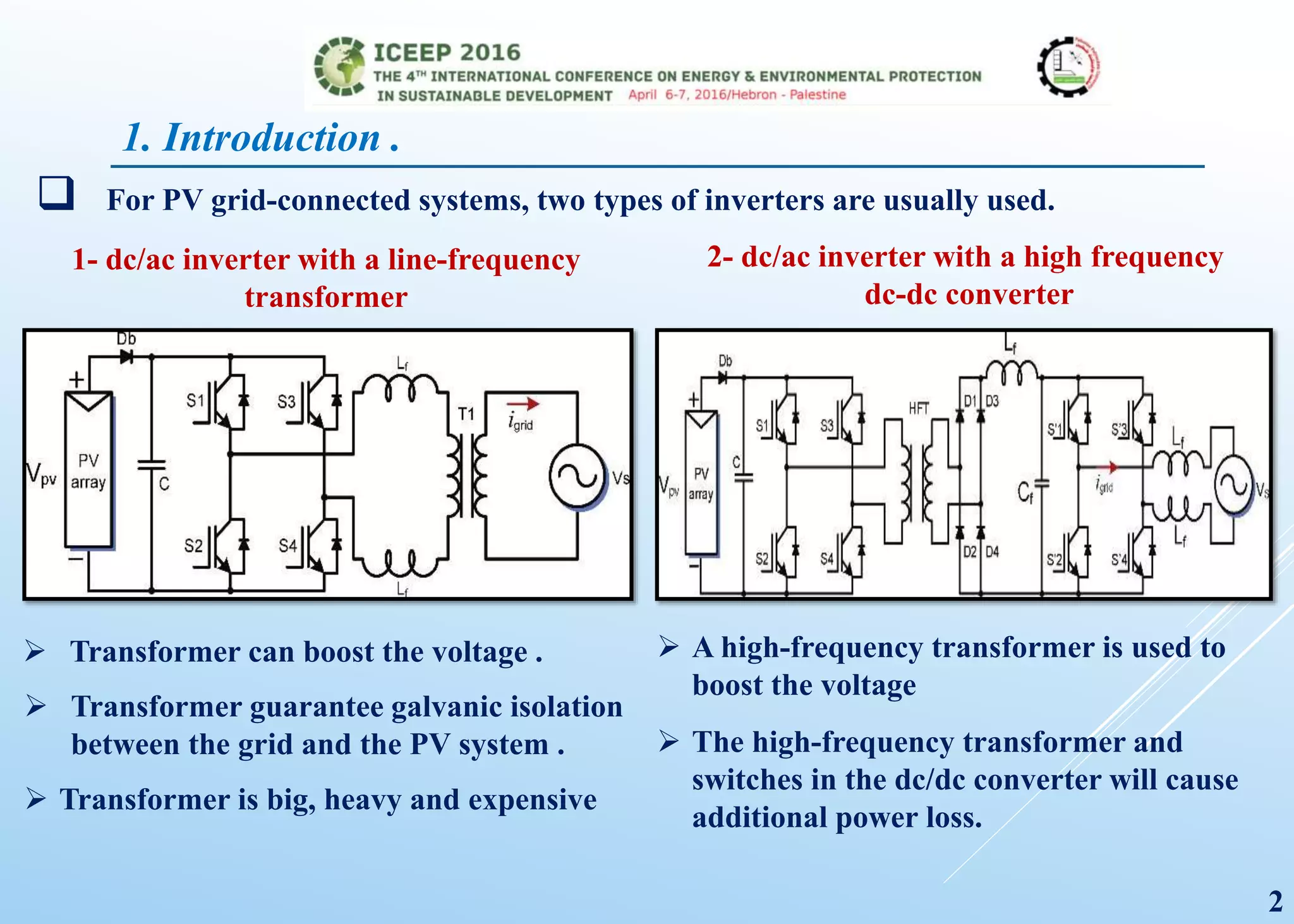
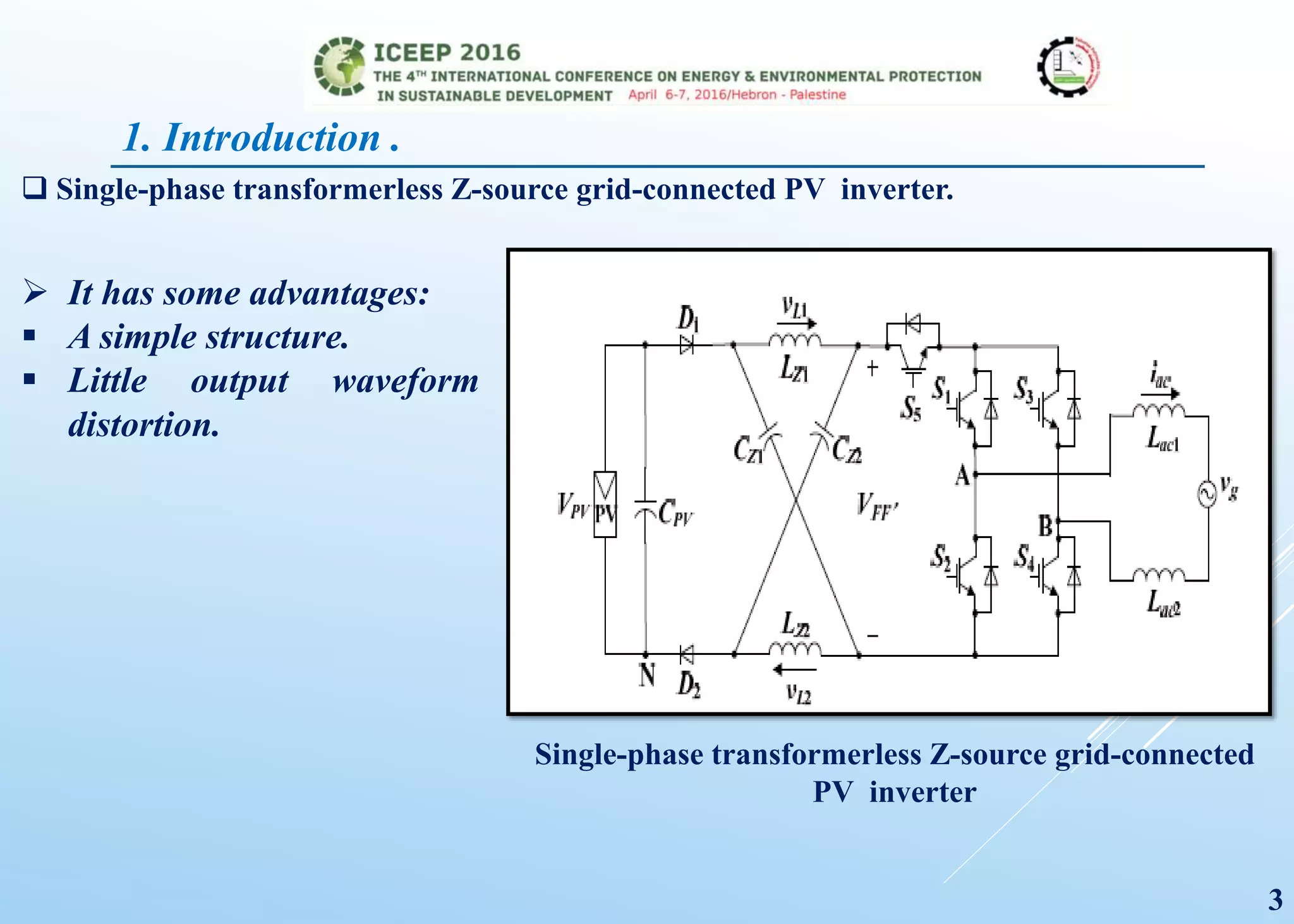
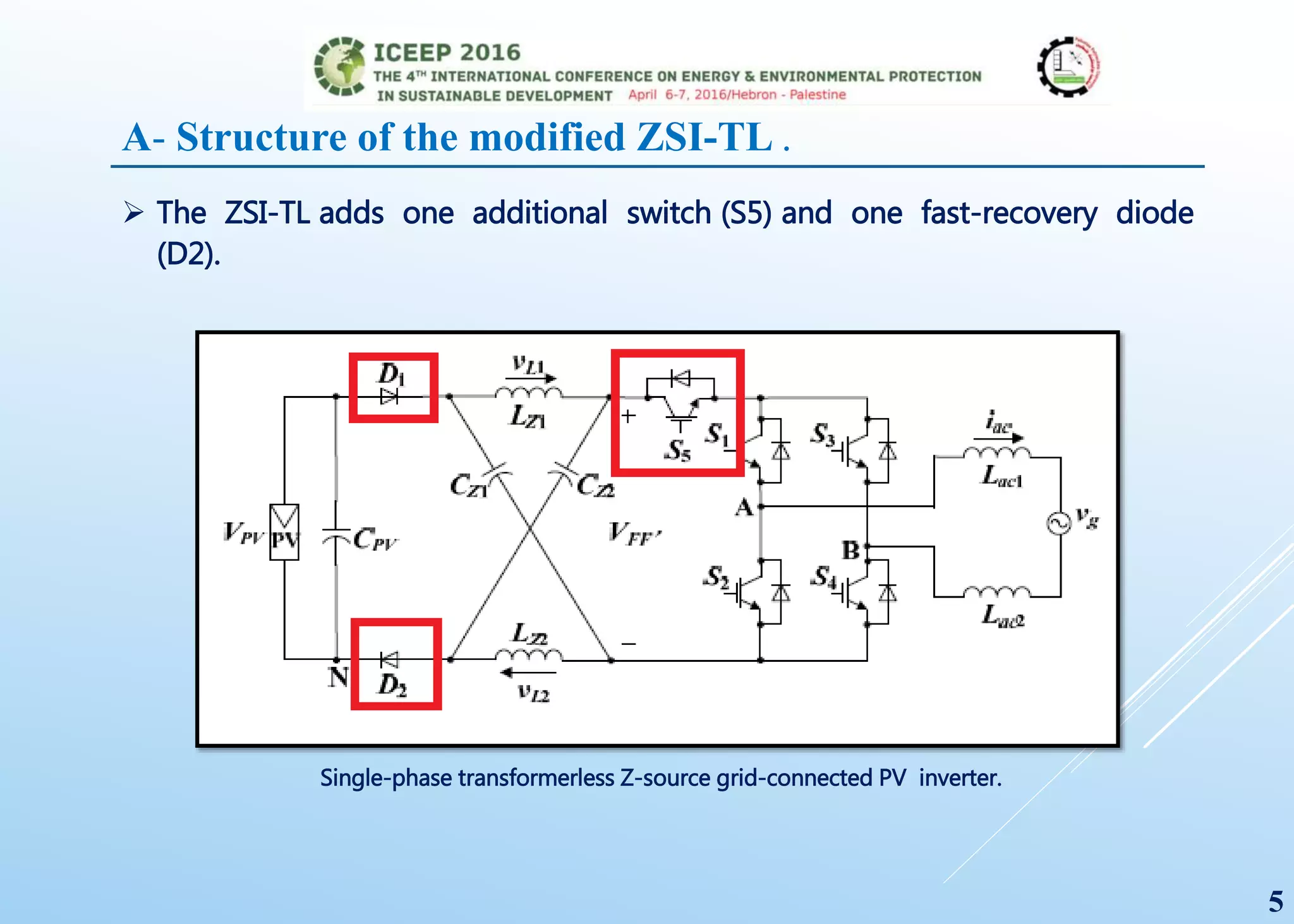
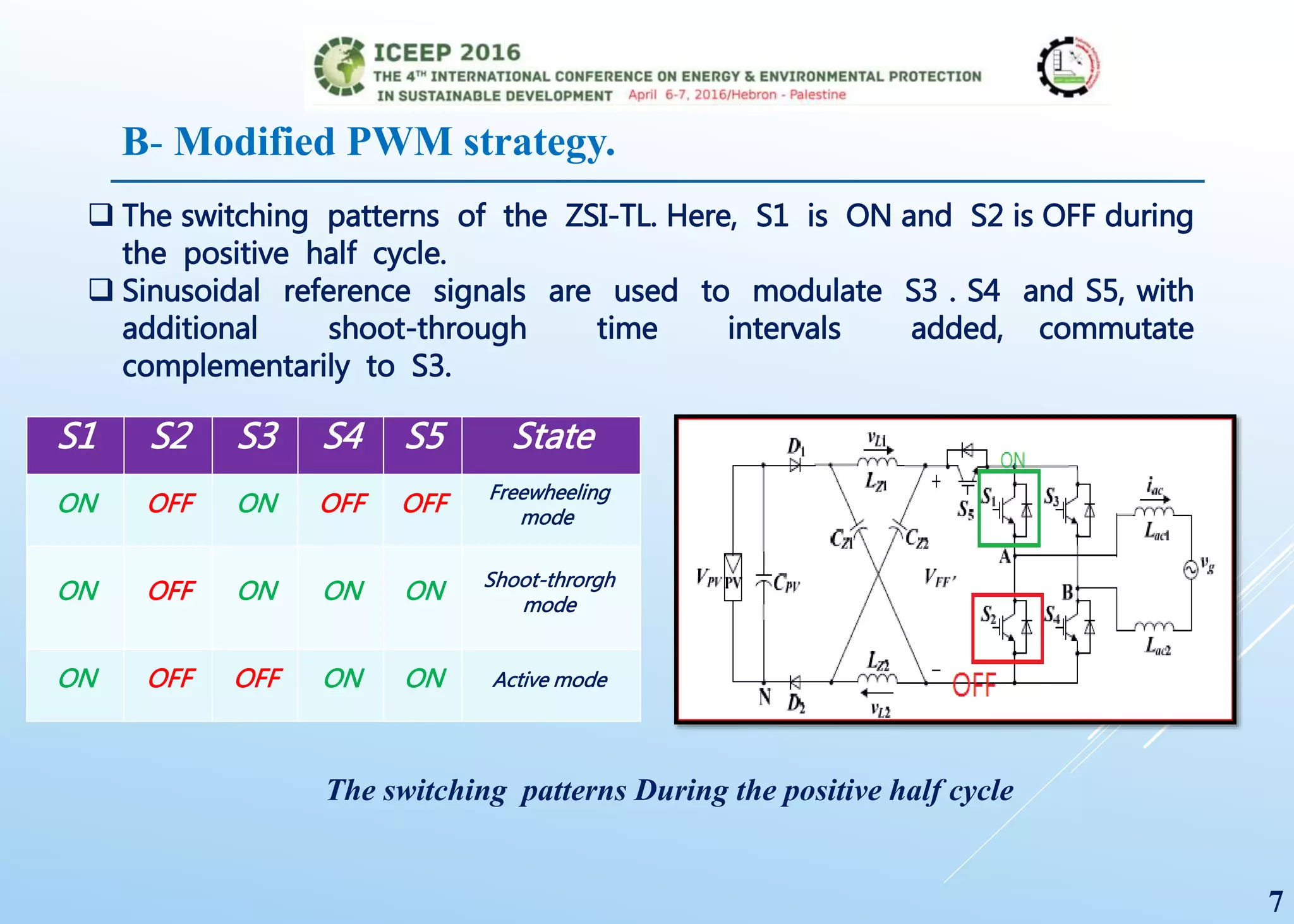
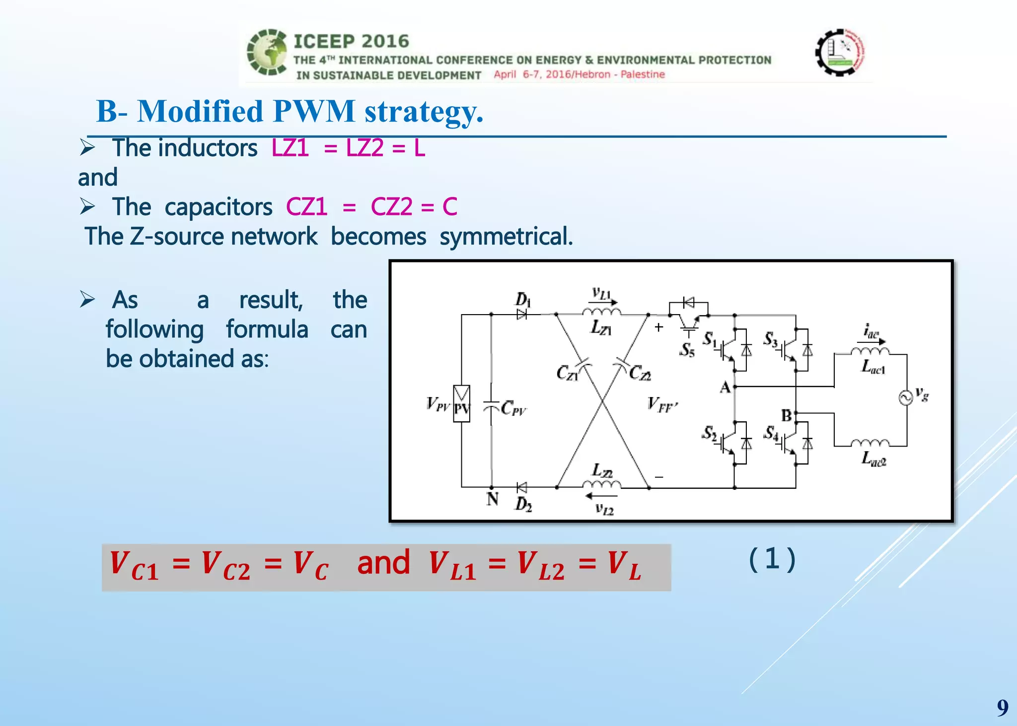
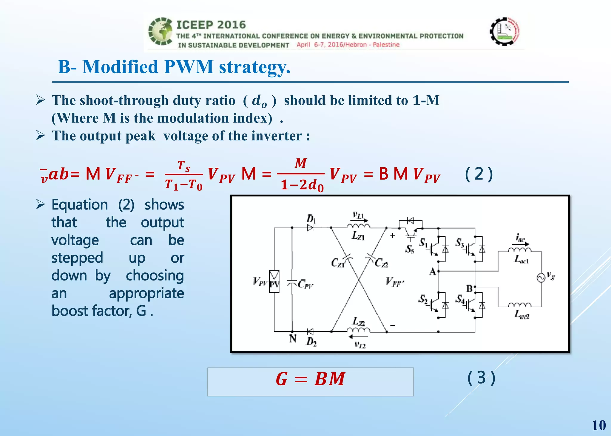
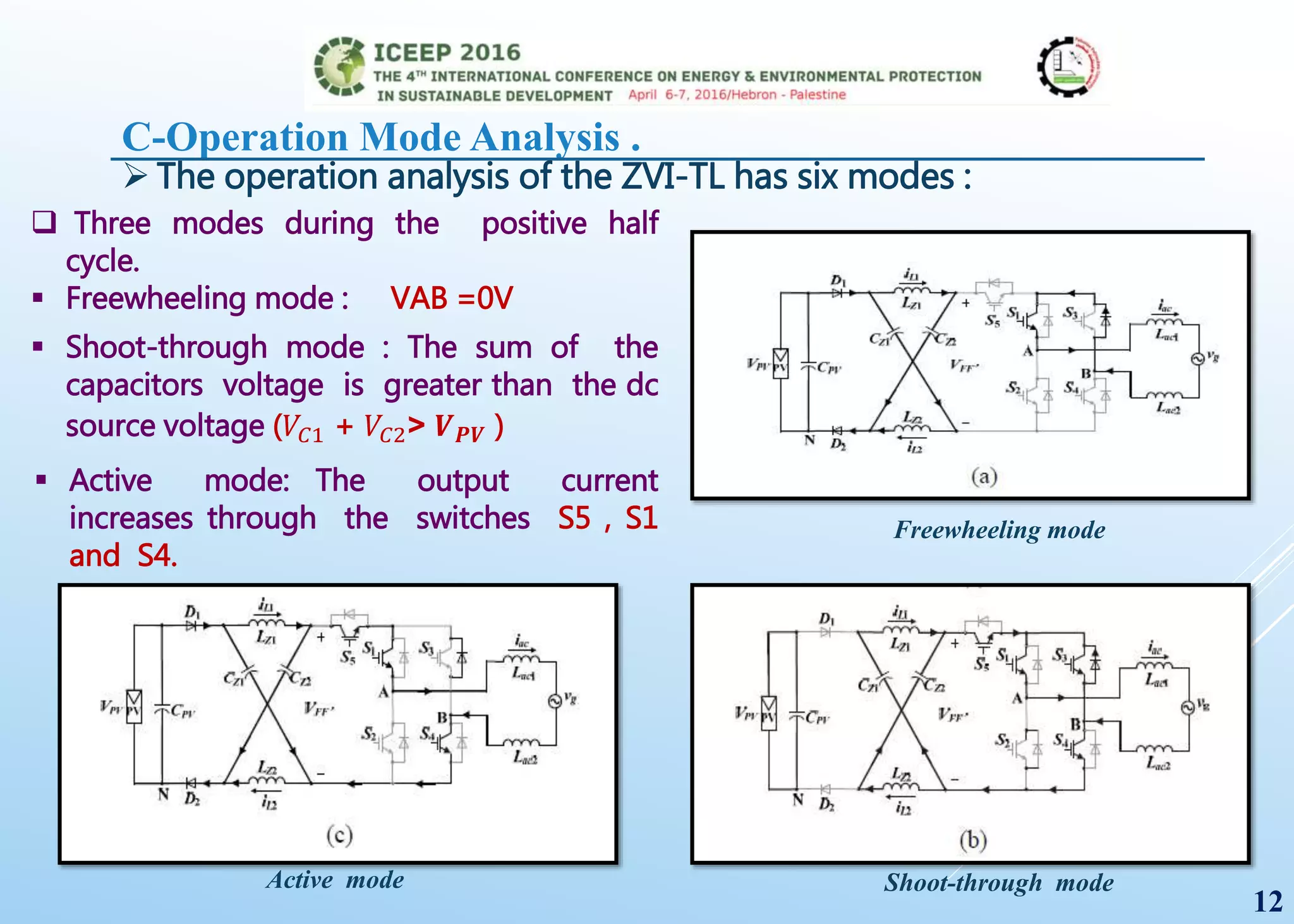
University of Turkish Aeronautical
Association
Faculty of Engineering
EEE department
Ibrahim Mahariq , and Hussein Mishbak
Department of Electrical and Electronics Engineering,
University of Turkish Aeronautical Association, Ankara 06790, Turkey
Ibrahim Mahariq:
• B.Sc, Palesitine Polytechnic University ( Electrical and Electronics Engineering)
• M.Sc, Middle East Technical University (Design of Electrical Machines by FEM)
• PhD1, Middle East Technical University (Computational Electromagnetics, Power sys)
• PhD2, TOBB University of Economics and Technology (Photonics)
• Assist. Prof. at the Department of Electrical and Electronics Engineering, University of
Turkish Aeronautical Association since Sep. 2014.
April 06,2016
imahariq@thk.edu.tr
1
OUTLINE:
1. Introduction .
2. Operation principles of the modified topology :
A- Structure of the Modified ZSI-TL .
C-Operation Mode Analysis .
B- Modified PWM Strategy.
3. Leakage current analysis of the ZSI-TL .
4. Simulation and results .
5. Conclusion .
1. Introduction .
1- dc/ac inverter with a line-frequency
transformer
2- dc/ac inverter with a high frequency
dc-dc converter
 For PV grid-connected systems, two types of inverters are usually used.
 Transformer can boost the voltage .
 Transformer guarantee galvanic isolation
between the grid and the PV system .
 Transformer is big, heavy and expensive
 A high-frequency transformer is used to
boost the voltage
 The high-frequency transformer and
switches in the dc/dc converter will cause
additional power loss.
2
Single-phase transformerless Z-source grid-connected
PV inverter
3
1. Introduction .
 Single-phase transformerless Z-source grid-connected PV inverter.
 It has some advantages:
 A simple structure.
 Little output waveform
distortion.
OUTLINE:
2. Operation principles of the modified topology :
A- Structure of the modified ZSI-TL .
B- Modified PWM strategy.
C- Operation mode analysis .
3. Leakage current analysis of the ZSI-TL .
4. Simulation and results .
5. Conclusion .
4
1. Introduction .
A- Structure of the modified ZSI-TL .
 The ZSI-TL adds one additional switch (S5) and one fast-recovery diode
(D2).
Single-phase transformerless Z-source grid-connected PV inverter.
5
OUTLINE:
1. Introduction .
2. Operation principles of the modified topology :
A- Structure of the modified ZSI-TL .
B- Modified PWM strategy.
C-Operation mode analysis .
3. Leakage current analysis of the ZSI-TL .
4. Simulation and results .
5. Conclusion .
6
 The switching patterns of the ZSI-TL. Here, S1 is ON and S2 is OFF during
the positive half cycle.
 Sinusoidal reference signals are used to modulate S3 . S4 and S5, with
additional shoot-through time intervals added, commutate
complementarily to S3.
S1 S2 S3 S4 S5 State
ON OFF ON OFF OFF Freewheeling
mode
ON OFF ON ON ON Shoot-throrgh
mode
ON OFF OFF ON ON Active mode
The switching patterns During the positive half cycle
7
B- Modified PWM strategy.
 Similarly, during the negative half cycle, S3 is ON and S4 is OFF.
 S1 commutates at the switching frequency.
 S2 and S5, with additional shoot-through time intervals added,
commutate complementarily to S1.
S1 S2 S3 S4 S5 State
ON OFF ON OFF OFF Freewheeling
mode
ON ON ON OFF ON Shoot-throrgh
mode
OFF ON ON OFF ON Active mode
The switching patterns During the negative half cycle
8
 The inductors LZ1 = LZ2 = L
and
 The capacitors CZ1 = CZ2 = C
The Z-source network becomes symmetrical.
 As a result, the
following formula can
be obtained as:
𝑽 𝑪𝟏 = 𝑽 𝑪𝟐 = 𝑽 𝑪 and 𝑽 𝑳𝟏 = 𝑽 𝑳𝟐 = 𝑽 𝑳 ( 1 )
9
B- Modified PWM strategy.
 The shoot-through duty ratio ( 𝒅 𝒐 ) should be limited to 𝟏-M
(Where M is the modulation index) .
 The output peak voltage of the inverter :
𝒗
−
𝒂𝒃= M 𝑽 𝑭𝑭 ¯ =
𝑻 𝒔
𝑻 𝟏−𝑻 𝟎
𝑽 𝑷𝑽 M =
𝑴
𝟏−𝟐𝒅 𝟎
𝑽 𝑷𝑽 = B M 𝑽 𝑷𝑽 ( 2 )
 Equation (2) shows
that the output
voltage can be
stepped up or
down by choosing
an appropriate
boost factor, G .
𝑮 = 𝑩𝑴 ( 3 )
10
B- Modified PWM strategy.
OUTLINE:
1. Introduction .
2. Operation principles of the modified topology :
A- Structure of the modified ZSI-TL .
B- Modified PWM strategy.
C-Operation mode analysis .
3. Leakage current analysis of the ZSI-TL .
4. Simulation and results .
5. Conclusion .
11
C-Operation Mode Analysis .
 The operation analysis of the ZVI-TL has six modes :
 Active mode: The output current
increases through the switches S5 , S1
and S4.
Freewheeling mode
Shoot-through mode
12
Active mode
 Three modes during the positive half
cycle.
 Freewheeling mode : VAB =0V
 Shoot-through mode : The sum of the
capacitors voltage is greater than the dc
source voltage (𝑉𝐶1 + 𝑉𝐶2˃ 𝑽 𝑷𝑽 )
C-Operation Mode Analysis .
Freewheeling mode
Shoot-through modeActive mode
 Three modes during the negative half
cycle.
 Freewheeling mode : VAB =0V
 Shoot-through mode : The sum of the
capacitors voltage is greater than the dc
source voltage (𝑉𝐶1 + 𝑉𝐶2˃ 𝑽 𝑷𝑽 )
 Active mode: The output current
increases through the switches S5 , S3
and S2.
13
OUTLINE:
1. Introduction .
2. Operation principles of the modified topology :
A- Structure of the modified ZSI-TL .
B- Modified PWM strategy.
C-Operation mode analysis .
3. Leakage current analysis of the ZSI-TL .
4. Simulation and results .
5. Conclusion .
14
3. Leakage current analysis of the ZSI-TL .
Model of the CM Voltage.
- The CM model for the ZSI-TL including the most significant stray elements :
Common-mode model for ZSI-TL ( Full model )
15
 CPVg =The capacitance
between the PV array and the
ground .
 Zpg =The series impedance
between the ground
connection points of the
inverter and the grid.
 The leakage current icm flows
through the closed-loop path
consisting of CPVg .
Model of the CM Voltage.
Common-mode model for ZSI-TL. (a) Full model.
(b)Simplified model.
 Without Zpg considered, the total CM
voltage 𝒗 𝒕𝒄𝒎 is :
𝑽 𝑡𝑐𝑚= 𝑽 𝑨𝑵+𝑽 𝑩𝑵
𝟐
+
𝑳 𝒂𝒄𝟐 − 𝑳 𝒂𝒄𝟏
𝟐(𝑳 𝒂𝒄𝟐 + 𝑳 𝒂𝒄𝟏)
𝑽 𝑨𝑵 − 𝑽 𝑩𝑵
….(4)
 From (4), if Lac1 = Lac2, the total CM
voltage is only relevant to VAN and VBN.
The CM voltage Vcm can be given by the
following:
𝑽 𝑐𝑚= 𝑽 𝑨𝑵+𝑽 𝑩𝑵
𝟐
…….….(5)
16
3. Leakage current analysis of the ZSI-TL .
Model of the CM Voltage.
Common-mode model for ZSI-TL. (a) Full model.
(b)Simplified model.
 𝑽 𝑨𝑵 and 𝑽 𝑩𝑵 are determined by the PWM strategy
of the ZSI-TL.
 SW1 and SW2 represent the diodes of the ZSI-TL.
 SW1 and SW2 are ON during the non-shoot-
through states, and they are OFF during the shoot-
through states.
 L12 is obtained by the following:
𝑳 𝒂𝒄𝟏 𝑳 𝒂𝒄𝟐
𝟐(𝑳 𝒂𝒄𝟏 + 𝑳 𝒂𝒄𝟐)
…….….(6)𝑳 𝟏𝟐=
17
3. Leakage current analysis of the ZSI-TL .
Model of the CM Voltage.
 In the active modes the CM voltage can
be expressed as:
Active mode
𝑽 𝑐𝑚= 𝑽 𝑨𝑵+𝑽 𝑩𝑵
𝟐
=
𝑽 𝑪−𝑽 𝑷𝑽−𝑽 𝑪
𝟐
=
𝑽 𝑷𝑽
𝟐
…….….(7)
Where VAN =VC and VBN =VPV -VC (Taking Mode 3 as an example).
 In the freewheeling modes the CM voltage
can be obtained as:
Freewheeling mode
𝑽 𝒄𝒎= 𝑽 𝑨𝑵+𝑽 𝑩𝑵
𝟐
=
𝑽 𝑷𝑽
𝟐
+
𝑽 𝑷𝑽
𝟐
𝟐
=
𝑉 𝑃𝑉
2
…….….(8)
18
3. Leakage current analysis of the ZSI-TL .
Model of the CM Voltage.
Shoot-through mode
Simplified model
 In the shoot-through modes SW1 and
SW2 are OFF so that the path for the
leakage current is blocked.
 According to the above analysis,
because the CM voltage is kept
constant during the non-shoot-
through states and the discharge
path of the CM voltage is blocked
during the shoot-through states, the
leakage current is avoided .
19
OUTLINE:
1. Introduction .
2. Operation principles of the modified topology :
A- Structure of the modified ZSI-TL .
B- Modified PWM strategy.
C-Operation mode analysis .
3. Leakage current analysis of the ZSI-TL .
4. Simulation and results .
5. Conclusion .
20
4. Simulation and results .
 The circuit has been tested to verify the
performance of the proposed ZVS-TL
topology.
 The detailed components and parameters
are as follows:
 VPV=100V.
 CZ1=CZ2=1000μF.
 LZ1=LZ2=4mH.
 Lac1=Lac2=4.5mH.
 Vg =220Vac.
 fg=50Hz.
 fS=4kHz.
 CPVg=0.1μF.
The voltages (VAN and VBN ) of the ZVI-TL
21
4. Simulation and results .
 The leakage current waveform of the ZVI-TL with a paralleled capacitor in the grid-cycle
and in the PWM cycle is shown.
 The leakage current icm is successfully limited to a very small value that is less than 50mA
for the peak value this complies with the DIN VDE 0126-1-1 standard.
The leakage current waveform of the ZVI-TL with a paralleled capacitor in the
grid-cycle and in the PWM cycle.
22
4. Simulation and results .
 It is clear that iL increases in the shoot-through mode and decreases in the non-
shoot-through mode.
 The dc-link voltage VFF¯ of the Z–source inductor and current iL waveforms.
The dc-link voltage 𝑽𝑭𝑭−
and the Z–source inductor
current iL waveforms.
23
The dc-link voltage VFF¯ the Z–source inductor current iL waveforms
The grid current and voltage waveforms with filerThe grid current and voltage waveforms without filter
The grid current and
voltage waveforms with
filter and without filter.
24
4. Simulation and results .
OUTLINE:
1. Introduction .
2. Operation principles of the modified topology :
A- Structure of the modified ZSI-TL .
B- Modified PWM strategy.
C-Operation mode analysis .
3. Leakage current analysis of the ZSI-TL .
4. Simulation and results .
5. Conclusion .
25
5. Conclusion .
 A low ac output current distortion can be achieved because there is no
dead time.
A modified transformerless Z-source PV grid-connected inverter in this
paper has the following characteristics:
26
 A decoupling switch and two reversed-biased diodes are used to eliminate the leakage
current.
 A modified PWM strategy is implemented, which ensures a single power device
switching per state transition.
 No shoot-through issue leads to a greatly enhanced reliability.
 These factors make the modified Z-source inverter suitable for high efficiency and low
leakage current transformerless PV grid-connected applications.
 Assist. Prof. Ibrahim Mahariq
 imahariq@thk.edu.tr
Contact information:

Eliminating leakage current in single phase transformerless z source inverter for photovoltaic system

  • 1.
    University of TurkishAeronautical Association Faculty of Engineering EEE department Ibrahim Mahariq , and Hussein Mishbak Department of Electrical and Electronics Engineering, University of Turkish Aeronautical Association, Ankara 06790, Turkey Ibrahim Mahariq: • B.Sc, Palesitine Polytechnic University ( Electrical and Electronics Engineering) • M.Sc, Middle East Technical University (Design of Electrical Machines by FEM) • PhD1, Middle East Technical University (Computational Electromagnetics, Power sys) • PhD2, TOBB University of Economics and Technology (Photonics) • Assist. Prof. at the Department of Electrical and Electronics Engineering, University of Turkish Aeronautical Association since Sep. 2014. April 06,2016 imahariq@thk.edu.tr
  • 2.
    1 OUTLINE: 1. Introduction . 2.Operation principles of the modified topology : A- Structure of the Modified ZSI-TL . C-Operation Mode Analysis . B- Modified PWM Strategy. 3. Leakage current analysis of the ZSI-TL . 4. Simulation and results . 5. Conclusion .
  • 3.
    1. Introduction . 1-dc/ac inverter with a line-frequency transformer 2- dc/ac inverter with a high frequency dc-dc converter  For PV grid-connected systems, two types of inverters are usually used.  Transformer can boost the voltage .  Transformer guarantee galvanic isolation between the grid and the PV system .  Transformer is big, heavy and expensive  A high-frequency transformer is used to boost the voltage  The high-frequency transformer and switches in the dc/dc converter will cause additional power loss. 2
  • 4.
    Single-phase transformerless Z-sourcegrid-connected PV inverter 3 1. Introduction .  Single-phase transformerless Z-source grid-connected PV inverter.  It has some advantages:  A simple structure.  Little output waveform distortion.
  • 5.
    OUTLINE: 2. Operation principlesof the modified topology : A- Structure of the modified ZSI-TL . B- Modified PWM strategy. C- Operation mode analysis . 3. Leakage current analysis of the ZSI-TL . 4. Simulation and results . 5. Conclusion . 4 1. Introduction .
  • 6.
    A- Structure ofthe modified ZSI-TL .  The ZSI-TL adds one additional switch (S5) and one fast-recovery diode (D2). Single-phase transformerless Z-source grid-connected PV inverter. 5
  • 7.
    OUTLINE: 1. Introduction . 2.Operation principles of the modified topology : A- Structure of the modified ZSI-TL . B- Modified PWM strategy. C-Operation mode analysis . 3. Leakage current analysis of the ZSI-TL . 4. Simulation and results . 5. Conclusion . 6
  • 8.
     The switchingpatterns of the ZSI-TL. Here, S1 is ON and S2 is OFF during the positive half cycle.  Sinusoidal reference signals are used to modulate S3 . S4 and S5, with additional shoot-through time intervals added, commutate complementarily to S3. S1 S2 S3 S4 S5 State ON OFF ON OFF OFF Freewheeling mode ON OFF ON ON ON Shoot-throrgh mode ON OFF OFF ON ON Active mode The switching patterns During the positive half cycle 7 B- Modified PWM strategy.
  • 9.
    B- Modified PWMstrategy.  Similarly, during the negative half cycle, S3 is ON and S4 is OFF.  S1 commutates at the switching frequency.  S2 and S5, with additional shoot-through time intervals added, commutate complementarily to S1. S1 S2 S3 S4 S5 State ON OFF ON OFF OFF Freewheeling mode ON ON ON OFF ON Shoot-throrgh mode OFF ON ON OFF ON Active mode The switching patterns During the negative half cycle 8
  • 10.
     The inductorsLZ1 = LZ2 = L and  The capacitors CZ1 = CZ2 = C The Z-source network becomes symmetrical.  As a result, the following formula can be obtained as: 𝑽 𝑪𝟏 = 𝑽 𝑪𝟐 = 𝑽 𝑪 and 𝑽 𝑳𝟏 = 𝑽 𝑳𝟐 = 𝑽 𝑳 ( 1 ) 9 B- Modified PWM strategy.
  • 11.
     The shoot-throughduty ratio ( 𝒅 𝒐 ) should be limited to 𝟏-M (Where M is the modulation index) .  The output peak voltage of the inverter : 𝒗 − 𝒂𝒃= M 𝑽 𝑭𝑭 ¯ = 𝑻 𝒔 𝑻 𝟏−𝑻 𝟎 𝑽 𝑷𝑽 M = 𝑴 𝟏−𝟐𝒅 𝟎 𝑽 𝑷𝑽 = B M 𝑽 𝑷𝑽 ( 2 )  Equation (2) shows that the output voltage can be stepped up or down by choosing an appropriate boost factor, G . 𝑮 = 𝑩𝑴 ( 3 ) 10 B- Modified PWM strategy.
  • 12.
    OUTLINE: 1. Introduction . 2.Operation principles of the modified topology : A- Structure of the modified ZSI-TL . B- Modified PWM strategy. C-Operation mode analysis . 3. Leakage current analysis of the ZSI-TL . 4. Simulation and results . 5. Conclusion . 11
  • 13.
    C-Operation Mode Analysis.  The operation analysis of the ZVI-TL has six modes :  Active mode: The output current increases through the switches S5 , S1 and S4. Freewheeling mode Shoot-through mode 12 Active mode  Three modes during the positive half cycle.  Freewheeling mode : VAB =0V  Shoot-through mode : The sum of the capacitors voltage is greater than the dc source voltage (𝑉𝐶1 + 𝑉𝐶2˃ 𝑽 𝑷𝑽 )
  • 14.
    C-Operation Mode Analysis. Freewheeling mode Shoot-through modeActive mode  Three modes during the negative half cycle.  Freewheeling mode : VAB =0V  Shoot-through mode : The sum of the capacitors voltage is greater than the dc source voltage (𝑉𝐶1 + 𝑉𝐶2˃ 𝑽 𝑷𝑽 )  Active mode: The output current increases through the switches S5 , S3 and S2. 13
  • 15.
    OUTLINE: 1. Introduction . 2.Operation principles of the modified topology : A- Structure of the modified ZSI-TL . B- Modified PWM strategy. C-Operation mode analysis . 3. Leakage current analysis of the ZSI-TL . 4. Simulation and results . 5. Conclusion . 14
  • 16.
    3. Leakage currentanalysis of the ZSI-TL . Model of the CM Voltage. - The CM model for the ZSI-TL including the most significant stray elements : Common-mode model for ZSI-TL ( Full model ) 15  CPVg =The capacitance between the PV array and the ground .  Zpg =The series impedance between the ground connection points of the inverter and the grid.  The leakage current icm flows through the closed-loop path consisting of CPVg .
  • 17.
    Model of theCM Voltage. Common-mode model for ZSI-TL. (a) Full model. (b)Simplified model.  Without Zpg considered, the total CM voltage 𝒗 𝒕𝒄𝒎 is : 𝑽 𝑡𝑐𝑚= 𝑽 𝑨𝑵+𝑽 𝑩𝑵 𝟐 + 𝑳 𝒂𝒄𝟐 − 𝑳 𝒂𝒄𝟏 𝟐(𝑳 𝒂𝒄𝟐 + 𝑳 𝒂𝒄𝟏) 𝑽 𝑨𝑵 − 𝑽 𝑩𝑵 ….(4)  From (4), if Lac1 = Lac2, the total CM voltage is only relevant to VAN and VBN. The CM voltage Vcm can be given by the following: 𝑽 𝑐𝑚= 𝑽 𝑨𝑵+𝑽 𝑩𝑵 𝟐 …….….(5) 16 3. Leakage current analysis of the ZSI-TL .
  • 18.
    Model of theCM Voltage. Common-mode model for ZSI-TL. (a) Full model. (b)Simplified model.  𝑽 𝑨𝑵 and 𝑽 𝑩𝑵 are determined by the PWM strategy of the ZSI-TL.  SW1 and SW2 represent the diodes of the ZSI-TL.  SW1 and SW2 are ON during the non-shoot- through states, and they are OFF during the shoot- through states.  L12 is obtained by the following: 𝑳 𝒂𝒄𝟏 𝑳 𝒂𝒄𝟐 𝟐(𝑳 𝒂𝒄𝟏 + 𝑳 𝒂𝒄𝟐) …….….(6)𝑳 𝟏𝟐= 17 3. Leakage current analysis of the ZSI-TL .
  • 19.
    Model of theCM Voltage.  In the active modes the CM voltage can be expressed as: Active mode 𝑽 𝑐𝑚= 𝑽 𝑨𝑵+𝑽 𝑩𝑵 𝟐 = 𝑽 𝑪−𝑽 𝑷𝑽−𝑽 𝑪 𝟐 = 𝑽 𝑷𝑽 𝟐 …….….(7) Where VAN =VC and VBN =VPV -VC (Taking Mode 3 as an example).  In the freewheeling modes the CM voltage can be obtained as: Freewheeling mode 𝑽 𝒄𝒎= 𝑽 𝑨𝑵+𝑽 𝑩𝑵 𝟐 = 𝑽 𝑷𝑽 𝟐 + 𝑽 𝑷𝑽 𝟐 𝟐 = 𝑉 𝑃𝑉 2 …….….(8) 18 3. Leakage current analysis of the ZSI-TL .
  • 20.
    3. Leakage currentanalysis of the ZSI-TL . Model of the CM Voltage. Shoot-through mode Simplified model  In the shoot-through modes SW1 and SW2 are OFF so that the path for the leakage current is blocked.  According to the above analysis, because the CM voltage is kept constant during the non-shoot- through states and the discharge path of the CM voltage is blocked during the shoot-through states, the leakage current is avoided . 19
  • 21.
    OUTLINE: 1. Introduction . 2.Operation principles of the modified topology : A- Structure of the modified ZSI-TL . B- Modified PWM strategy. C-Operation mode analysis . 3. Leakage current analysis of the ZSI-TL . 4. Simulation and results . 5. Conclusion . 20
  • 22.
    4. Simulation andresults .  The circuit has been tested to verify the performance of the proposed ZVS-TL topology.  The detailed components and parameters are as follows:  VPV=100V.  CZ1=CZ2=1000μF.  LZ1=LZ2=4mH.  Lac1=Lac2=4.5mH.  Vg =220Vac.  fg=50Hz.  fS=4kHz.  CPVg=0.1μF. The voltages (VAN and VBN ) of the ZVI-TL 21
  • 23.
    4. Simulation andresults .  The leakage current waveform of the ZVI-TL with a paralleled capacitor in the grid-cycle and in the PWM cycle is shown.  The leakage current icm is successfully limited to a very small value that is less than 50mA for the peak value this complies with the DIN VDE 0126-1-1 standard. The leakage current waveform of the ZVI-TL with a paralleled capacitor in the grid-cycle and in the PWM cycle. 22
  • 24.
    4. Simulation andresults .  It is clear that iL increases in the shoot-through mode and decreases in the non- shoot-through mode.  The dc-link voltage VFF¯ of the Z–source inductor and current iL waveforms. The dc-link voltage 𝑽𝑭𝑭− and the Z–source inductor current iL waveforms. 23 The dc-link voltage VFF¯ the Z–source inductor current iL waveforms
  • 25.
    The grid currentand voltage waveforms with filerThe grid current and voltage waveforms without filter The grid current and voltage waveforms with filter and without filter. 24 4. Simulation and results .
  • 26.
    OUTLINE: 1. Introduction . 2.Operation principles of the modified topology : A- Structure of the modified ZSI-TL . B- Modified PWM strategy. C-Operation mode analysis . 3. Leakage current analysis of the ZSI-TL . 4. Simulation and results . 5. Conclusion . 25
  • 27.
    5. Conclusion . A low ac output current distortion can be achieved because there is no dead time. A modified transformerless Z-source PV grid-connected inverter in this paper has the following characteristics: 26  A decoupling switch and two reversed-biased diodes are used to eliminate the leakage current.  A modified PWM strategy is implemented, which ensures a single power device switching per state transition.  No shoot-through issue leads to a greatly enhanced reliability.  These factors make the modified Z-source inverter suitable for high efficiency and low leakage current transformerless PV grid-connected applications.
  • 28.
     Assist. Prof.Ibrahim Mahariq  imahariq@thk.edu.tr Contact information: