Here are the steps to load single-sheet paper:
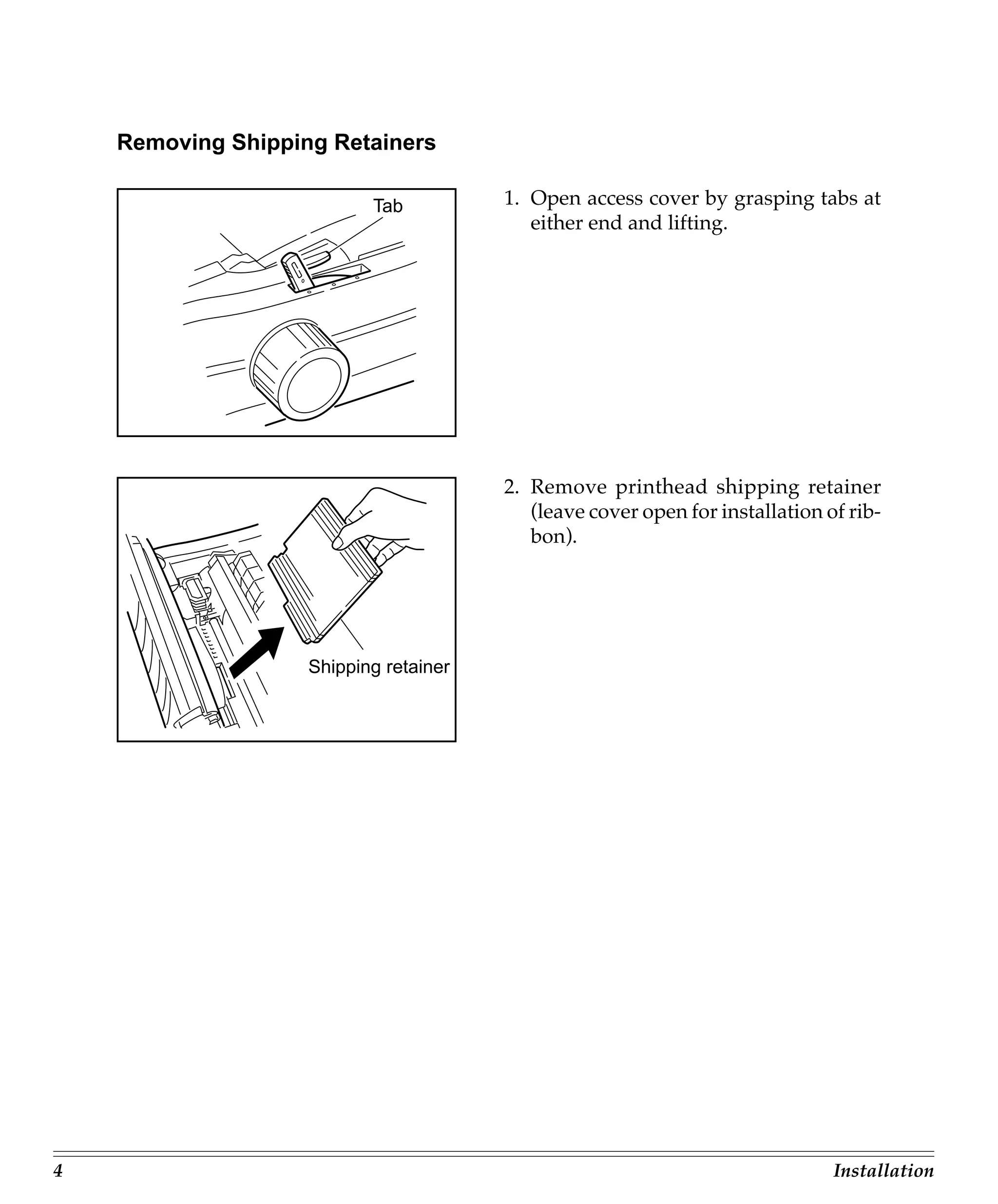
1. Open the top cover by lifting up on the tab.
2. Slide the paper guides outward.
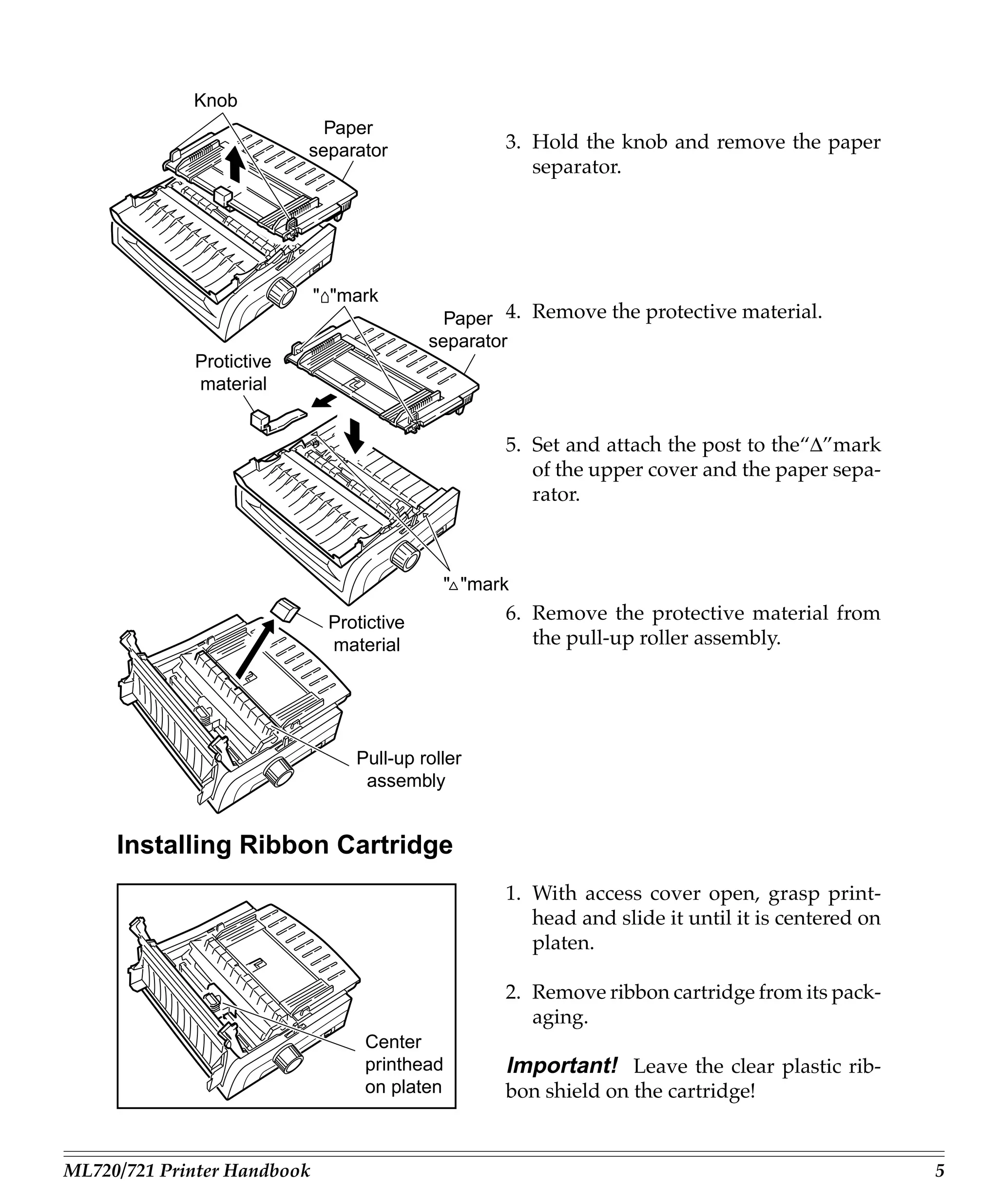
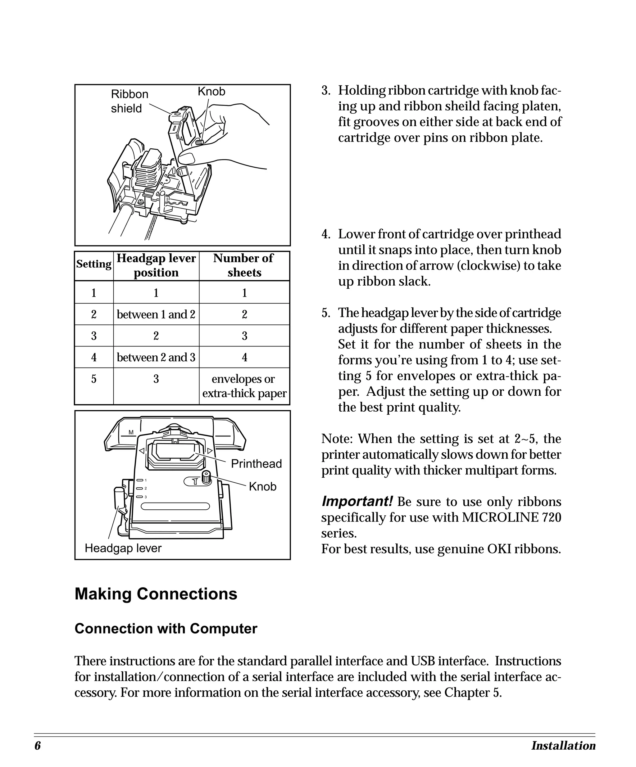
3. Fan the stack of paper you want to load and place it face up in the tray with the top
edge going in first.
4. Slide the paper guides inward until they touch the edges of the paper.
5. Lower the top cover until it clicks into place.
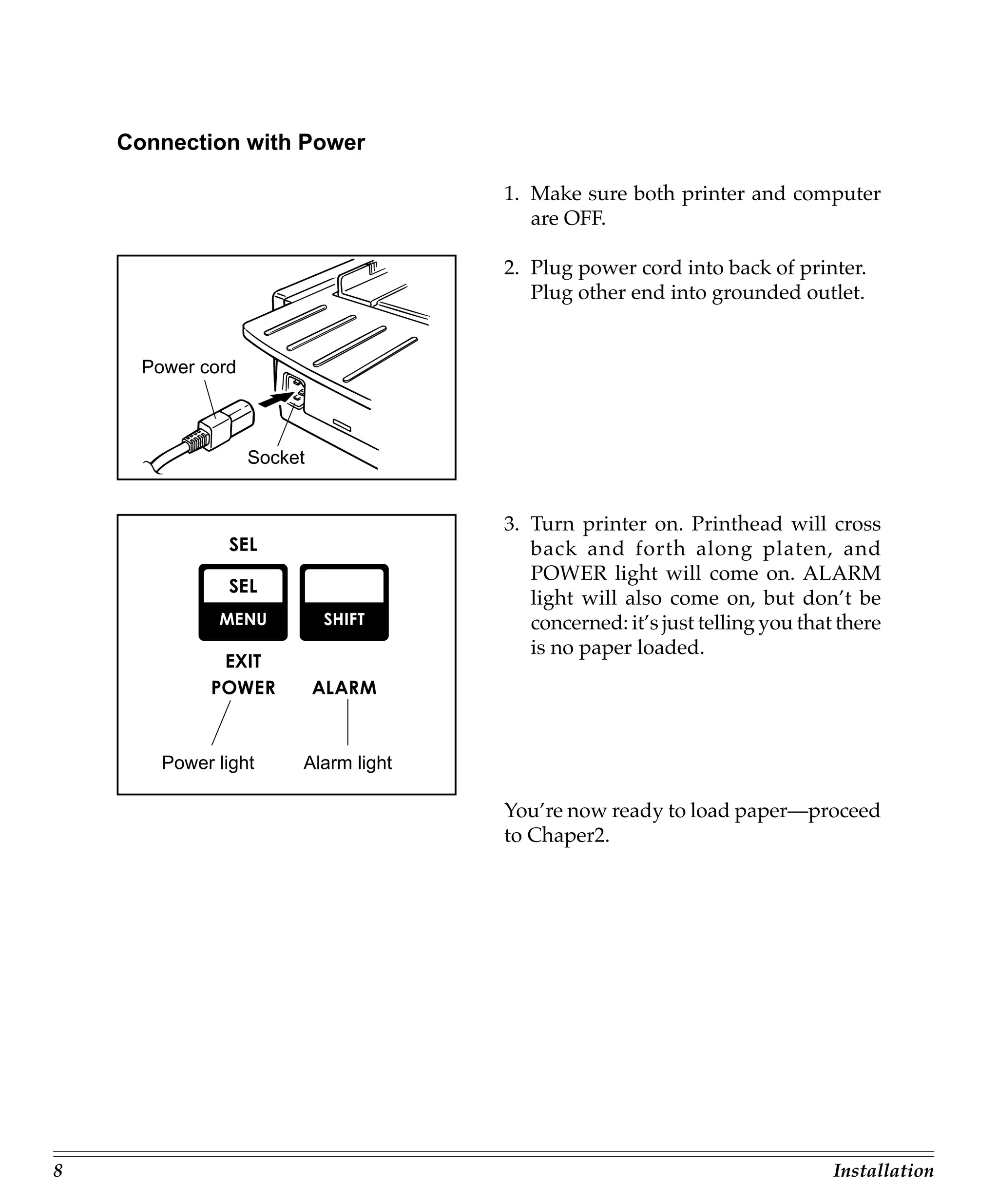
6. Press the FEED button to feed the top sheet into position for printing.
Be sure to load only one sheet at a time for best results. You can now start printing from your application software.


![Chapter 2: Loading Paper
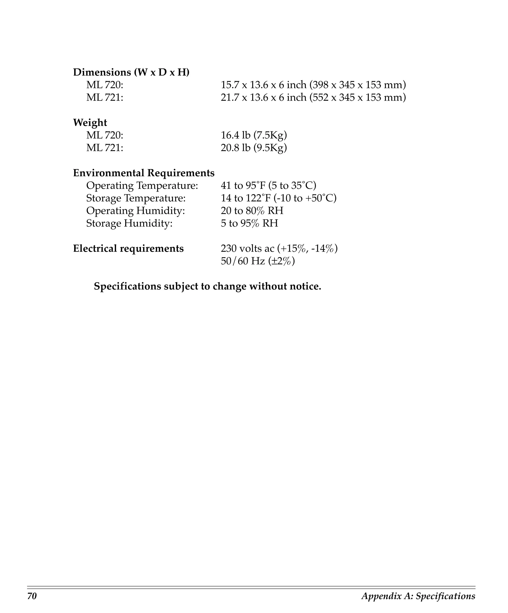
Your printer has provision for single-sheet paper feed from the top and for continu-
ous-form paper feed from the rear. You can also install options: the Cut Sheet Feeder,
which holds a stack of 100 sheets for feeding from the top and the Push and/or Pull
Tractors for feeding continuous-form labels, heavy card stock or multi-part forms from
the bottom. See Chapter 5 for more information on these options.
Top Feed
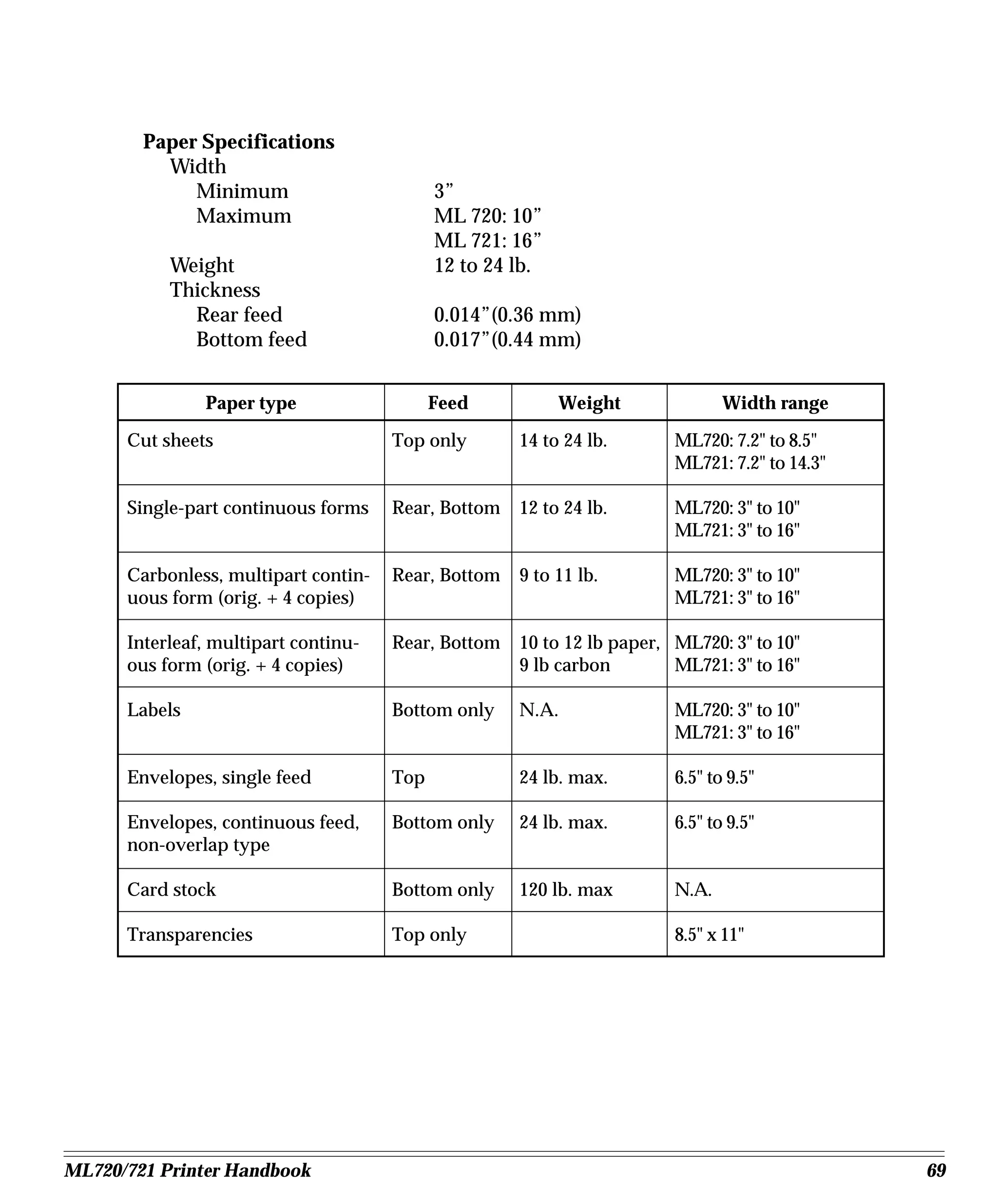
• Single sheets (basis weight 14 to 24 lbs)
• Single envelopes
– 24-lb maximum
– 6.5” to 9.5” wide
• Transparencies (8.5 x 11”)
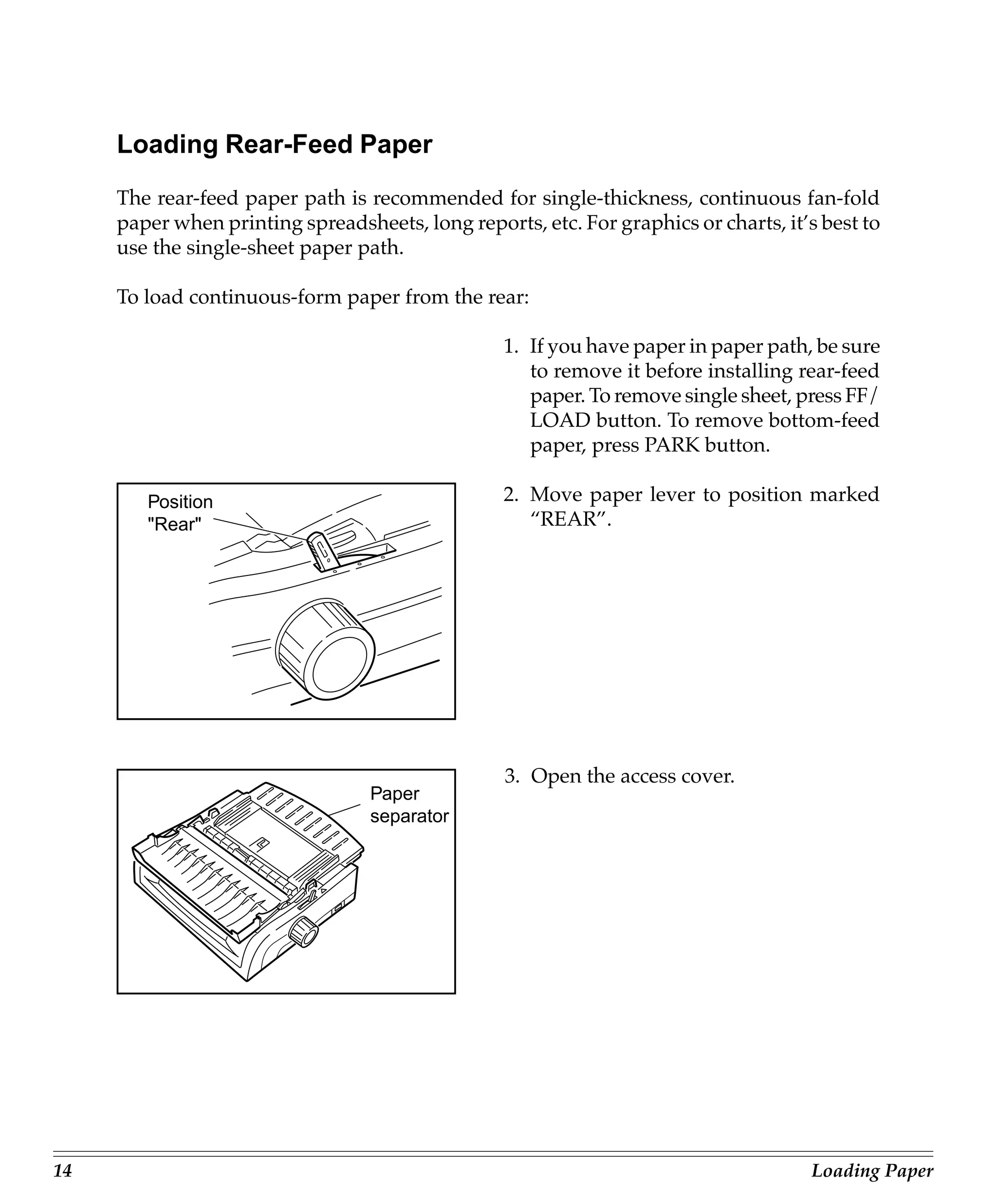
Rear feed (continuous forms only, thickness to 0.014” [0.36 mm])
• Single-part continuous forms
– 12 to 24 lb.
– Minimum 3” wide (*1)
• Carbonless, multi-part forms
– Original, plus 4 copies
– 9 to 11 lb
– Minimum 3” wide (*1)
• Interleaf, multi-part forms (with carbon paper)
– Original, plus 4 copies
– 10 to 12 lb paper, with 9 lb carbon
– Minimum 3” wide (*1)
(*1) Please change mentioned below centering Position within a set-up group fol-
lowing indication of 32 pages when a form of 3” wide is used by Rear Feed.
In the case of ML720 “Mode 1”.
In the case of ML721 “Mode 2”.
ML720/721 Printer Handbook 9](https://image.slidesharecdn.com/ml721-130321022809-phpapp01/75/Ml721-16-2048.jpg)
![Bottom feed (continuous forms only, thickness to 0.017” [0.44mm])
• Single-part continuous forms
– 12 to 24 lb
– Minimum 3” wide (*2)
• Carbonless, multi-part forms
– Original, plus 5 copies
– 9 to 11 lb
– Minimum 3” wide (*2)
• Interleaf, multi-part forms (with carbon paper)
– Original, plus 4 copies
– 10 to 12 lb paper, with 9 lb carbon
– Minimum 3” wide (*2)
• Continuous-feed envelopes
– 24 lb maximum
– 6.5” to 9.5” wide (envelope itself)
• Labels
– minimum 3” wide (*2)
– maximum 10”(ML720) or 16” (ML721) wide
• Card stock: papers up to 120 lb maximum
(*2) Please change mentioned below centering Position within a set-up group fol-
lowing indication of 32 pages when a form of 3” wide is used by Bottom Feed.
In the case of ML720 “Mode 1”.
In the case of ML721 “Mode 2”.
10 Loading Paper](https://image.slidesharecdn.com/ml721-130321022809-phpapp01/75/Ml721-17-2048.jpg)


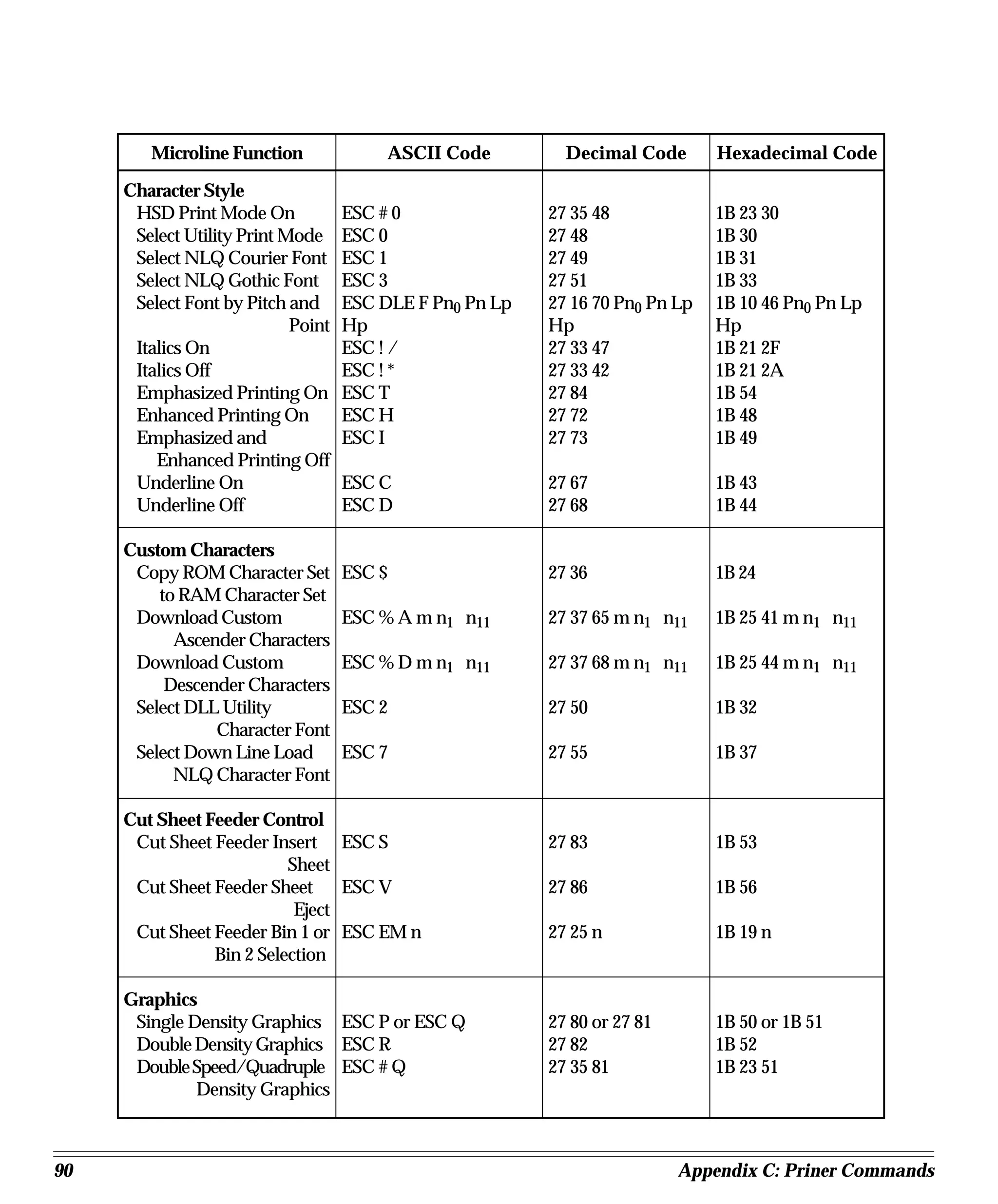
![Appendix C: Printer Commands
This appendix contains a listing of the printer commands for the IBM proprinter, Epson
FX, and OKI MICROLINE emulations, grouped by function.
IBM Proprinter Printer Commands
IBM Function ASCII Code Decimal Code Hexadecimal Code
Bar Code Commands
Select Bar Code Type ESC DLE A m n1 n8 27 16 65 m n1 n8 1B 10 41 m n1 n8
and Size
Print Bar Code Data ESC DLE B m n [data] 27 16 66 m n [data] 1B 10 42 m n [data]
Print Postnet Bar Code ESC DLE C n [data] 27 16 67 n [data] 1B 10 43 n [data]
Data
Select Bar Code Type ESC [ f Ln Hn Pk Pm Ps 27 91 102 Ln Hn Pk 1B 5B 66 Ln Hn Pk
Lv Hv Pc Pm Ps Lv Hv Pc Pm Ps Lv Hv Pc
Print Bar Code ESC [ f Ln Hn DATA 27 91 112 Ln Hn 1B 5B 70 Ln Hn
DATA DATA
Character Sets
Select IBM Character Set I ESC 7 27 55 1B 37
Select IBM Character Set ESC 6 27 54 1B 36
II
Print from IBM ESC Ln Hn 27 92 Ln Hn 1B 5C Ln Hn
Character Set III
Print One Character from ESC n 27 94 n 1B 5E n
IBM Character Set III
Select International ESC ! n 27 33 n 1B 21 n
Character Set *
Select Code Page ESC [ TLn Hn 0 0 Hcp Lcp 27 91 84 Ln Hn 0 0 1B 5B 54 Ln Hn 0 0
0 Hcp Lcp 0 Hcp Lcp 0
Character Size/Spacing
Select 10 cpi Pitch DC2 18 12
Select 12 cpi Pitch ESC : 27 58 1B 3A
Select 15 cpi Pitch * ESC g 27 103 1B 67
Select 20 cpi Pitch * ESC SI 27 15 1B 0F
Set Compressed Pitch SI 15 0F
Superscript Printing On ESC S 1 27 83 1 1B 53 01
Subscript Printing On ESC S 0 27 83 0 1B 53 00
Super script/Subscript ESC T 27 84 1B 54
ML720/721 Printer Handbook 81](https://image.slidesharecdn.com/ml721-130321022809-phpapp01/75/Ml721-88-2048.jpg)

![IBM Function ASCII Code Decimal Code Hexadecimal Code
Graphics
Single Density Graphics ESC K Ln Hn [data] 27 75 Ln Hn [data] 1B 4B Ln Hn [data]
Double Density Graphics ESC L Ln Hn [data] 27 76 Ln Hn [data] 1B 4C Ln Hn [data]
Double Speed/Double ESC Y Ln Hn [data] 27 89 Ln Hn [data] 1B 59 Ln Hn [data]
Density Graphics
Quadruple Density ESC Z Ln Hn [data] 27 90 Ln Hn [data] 1B 5A Ln Hn [data]
Graphics
Horizontal Control
Backspace BS 8 08
Carriage Return CR 13 0D
Margin Setting, Left & ESC X n m 27 88 n m 1B 58 n m
Right
Horizontal Tab HT 9 09
Set Horizontal Tab ESC D n1 n2 nk 0 27 68 n1 n2 nk 0 1B 44 n1 n2 nk 0
Clear Horizontal Tab ESC D 0 0 27 68 0 0 1B 44 0 0
Settings
Set 4-column Tabulation * ESC % B n1 n2 n3 n4 27 37 66 n1 n2 n3 n4 1B 25 42 n1 n2 n3 n4
Set Print Position * ESC DLE @ Pn A1 A2 P1 27 16 64 Pn A1 A2 1B 10 40 Pn A1 A2 P1
P2 P3 P4 P1 P2 P3 P4 P2 P3 P4
Set Relative Dot Position * ESC | Ln Hn 27 124 Ln Hn 1B 7C Ln Hn
Uni-directional Print On ESC U 1 27 85 1 1B 55 1
Uni-directional Print Off ESC U 0 27 85 0 1B 55 00
Set Relative Print Position ESC d Ln Hn 27 100 Ln Hn 1B 64 Ln Hn
Vertical Control
Page Length, Set in n ESC C 0 n 27 67 0 n 1B 43 00 n
Inches
Page Length, Set in Lines ESC C n 27 67 n 1B 43 n
Skip Over Perforation On ESC N n 27 78 n 1B 4E n
Skip Over Perforation Off ESC O 27 79 1B 4F
Set Top of Form at ESC 4 27 52 1B 34
Current Position
Form Feed FF 12 0C
Line Feed LF 10 0A
Perform n/216" Line Feed ESC J n 27 74 n 1B 4A n
Perform n/144" Line Feed ESC % 5 n 27 37 53 n 1B 25 35 n
Auto Line Feed On ESC 5 1 27 53 1 1B 35 01
Auto Line Feed Off ESC 5 0 27 53 0 1B 35 00
Reverse Line Feed ESC ] 27 93 1B 5D
Set Line Spacing to 7/72" ESC 1 27 49 1B 31
Set Line Spacing to 1/8" ESC 0 27 48 1B 30
ML720/721 Printer Handbook 83](https://image.slidesharecdn.com/ml721-130321022809-phpapp01/75/Ml721-90-2048.jpg)

![Epson FX Printer Commands
Epson Function ASCII Code Decimal Code Hexadecimal Code
Bar Code Commands
Select Bar Code Type ESC DLE A m n1 n8 27 16 65 m n1 n8 1B 10 41 m n1 n8
and Size *
Print Bar Code Data * ESC DLE B m n [data] 27 16 66 m n [data] 1B 10 42 m n [data]
Print Postnet Bar Code ESC DLE C n [data] 27 16 67 n [data] 1B 10 43 n [data]
Data *
Print Bar Code ESC ( B Ln Hn Pk Pm Ps 27 40 66 Ln Hn Pk 1B 28 42 Ln Hn Pk
Lv Hv Pc DATA Pm Ps Lv Hv Pc Pm Ps Lv Hv Pc
DATA DATA
Character Sets
Select International ESC R n 27 82 n 1B 52 n
Character Set
Select Epson Character ESC t n 27 116 n 1B 74 n
Set
Permit Printing of Upper ESC 6 or ESC I 1 27 54 or 27 73 1 1B 36 or 1B 49 01
Range Control Codes
Cancel Printing of Upper ESC 7 or ESC I 0 27 55 or 27 73 0 1B 37 or 1B 49 00
Range Control Codes
Character table selection ESC ( t Ln Hn Pn1 Pn2 27 40 116 Ln Hn Pn1 1B 28 74 Ln Hn Pn1
Pn3 Pn2 Pn3 Pn2 Pn3
Character Size/Spacing
Select 10 cpi Pitch ESC P 27 80 1B 50
Select 12 cpi Pitch ESC M 27 77 1B 4D
Select 15 cpi Pitch ESC g 27 103 1B 67
Select 20 cpi Pitch ESC SI 27 15 1B 0F
Cancel 20 cpi Pitch DC2 18 12
Set Compressed Pitch SI 15 0F
Superscript Printing On ESC S 1 27 83 1 1B 53 01
Subscript Printing On ESC S 0 27 83 0 1B 53 00
Superscript/Subscript ESC T 27 84 1B 54
Printing Off
Begin Double Width ESC SO 27 14 1B 0E
Printing Line by Line
End Double Width DC 4 20 14
Printing Line by Line
Double Width Printing ESC W 1 27 87 1 1B 57 01
On
Double Width Printing ESC W 0 27 87 0 1B 57 00
Off
ML720/721 Printer Handbook 85](https://image.slidesharecdn.com/ml721-130321022809-phpapp01/75/Ml721-92-2048.jpg)
![Epson Function ASCII Code Decimal Code Hexadecimal Code
Character Size/Spacing
(cont.)
Double Height Printing On ESC w n 27 119 n 1B 77 n
Proportional Spacing On ESC p 1 27 112 1 1B 70 01
Proportional Spacing Off ESC p 0 27 112 0 1B 70 00
Set Intercharacter Spacing ESC SP n 27 32 n 1B 20 n
Character Style
Select HSD Print Mode * ESC ( n 27 40 n 1B 28 n
Select Utility or NLQ ESC x n 27 120 n 1B 78 n
Print Mode
Select Draft Font ESC y Pn 27 40 85 Pn 1B 28 55 Pn
Select font by Pitch and ESC X Pn Lp Hp 27 88 Pn Lp Hp 1B 58 Pn Lp Hp
Point
Select NLQ Type ESC k n 27 107 n 1B 6B n
Composite Command ESC ! n 27 33 n 1B 21 n
Italics On ESC 4 27 52 1B 34
Italics Off ESC 5 27 53 1B 35
Emphasized Printing On ESC E 27 69 1B 45
Emphasized Printing Off ESC F 27 70 1B 46
Enhanced Printing On ESC G 27 71 1B 47
Enhanced Printing Off ESC H 27 72 1B 48
Underline On ESC - 1 27 45 1 1B 2D 01
Underline Off ESC - 0 27 45 0 1B 2D 00
Custom Characters
Down Line Load Custom ESC & 0 n1 n2 a [data] 27 38 0 n1 n2 a [data] 1B 26 00 n1 n2 a [data]
Characters
Copy ROM Character Set ESC : 0 n 0 27 58 0 n 0 1B 3A 0 n 0
to RAM Character Set
Custom Character Set On ESC % 0 27 37 0 1B 25 00
Custom Character Set Off ESC % 1 27 37 1 1B 25 01
Cut Sheet Feeder Control
Insert/Eject Paper ESC EM n 27 25 n 1B 19 n
Graphics
Single Density Graphics ESC K L n Hn [data] 27 75 L n Hn [data] 1B 4B L n Hn [data]
Double Density Graphics ESC L L n Hn [data] 27 76 L n Hn [data] 1B 4C L n Hn [data]
Double Speed/Double ESC Y L n Hn [data] 27 89 L n Hn [data] 1B 59 L n Hn [data]
Density Graphics
Quadruple Density ESC Z L n Hn [data] 27 90 L n Hn [data] 1B 5A L n Hn [data]
Graphics
86 Appendix C: Priner Commands](https://image.slidesharecdn.com/ml721-130321022809-phpapp01/75/Ml721-93-2048.jpg)
![Epson Function ASCII Code Decimal Code Hexadecimal Code
Graphics (cont.)
Graphics Select/Print ESC * m Ln Hn [data] 27 42 m Ln Hn [data] 1B 2A m Ln Hn [data]
Reassign Graphics ESC ? m n 27 63 m n 1B 3F m n
Select 9-pin Graphics ESC m Ln Hn [data] 27 94 m Ln Hn [data] 1B 5E m Ln Hn [data]
Printing
Horizontal Control
Backspace BS 8 08
Carriage Return CR 13 0D
Margin Setting, Left ESC l n 27 108 n 1B 6C n
Margin Setting, Right ESC Q n 27 81 n 1B 51 n
Horizontal Tab HT 9 09
Set Horizontal Tab ESC D n1 n2 nk 0 27 68 n1 n2 nk 0 1B 44 n1 n2 nk 00
Clear Horizontal Tab ESC D 0 0 27 68 0 0 1B 44 00 00
Settings
Set Print Position ESC DLE @ Pn A1 A2 P1 27 16 64 Pn A1 A2 1B 10 40 Pn A1 A2 P1
P2 P3 P4 P1 P2 P3 P4 P2 P3 P4
Set Absolute Dot Position ESC $ Ln Hn 27 36 Ln Hn 1B 24 Ln Hn
Set Relative Dot Position ESC Ln Hn 27 92 Ln Hn 1B 5C Ln Hn
Uni-directional Print On ESC U 1 27 85 1 1B 55 01
Uni-directional Print Off ESC U 0 27 85 0 1B 55 00
Print Uni-directional for ESC < 27 60 1B 3C
One Line
Vertical Control
Page Length, Set in n ESC C 0 n 27 67 0 n 1B 43 00 n
Inches
Page Length, Set in Lines ESC C n 27 67 n 1B 43 n
Skip Over Perforation Set ESC N n 27 78 n 1B 4E n
Skip Over Perforation ESC O 27 79 1B 4F
Reset to Default
Form Feed FF 12 0C
Line Feed LF 10 0A
Perform n/216" Line Feed ESC J n 27 74 n 1B 4A n
Perform n/144" Line Feed * ESC % 5 n 27 37 53 n 1B 25 35 n
n/216" Reverse Line Feed ESC j n 27 106 n 1B 6A n
Set Line Spacing to 1/6" ESC 2 27 50 1B 32
Set Line Spacing to 1/8" ESC 0 27 48 1B 30
Set Line Spacing to 7/72" ESC 1 27 49 1B 31
Set Line Spacing to n/72" ESC A n 27 65 n 1B 41 n
Set Line Spacing to n/144" * ESC % 9 n 27 37 57 n 1B 25 39 n
ML720/721 Printer Handbook 87](https://image.slidesharecdn.com/ml721-130321022809-phpapp01/75/Ml721-94-2048.jpg)

![OKI Microline (ML) Printer Commands
Microline Function ASCII Code Decimal Code Hexadecimal Code
Bar Code Commands
Select Bar Code Type ESC DLE A m n1 n8 27 16 65 m n1 n8 1B 10 41 m n1 n8
and Size
Print Bar Code Data ESC DLE B n [data] 27 16 66 n [data] 1B 10 42 n [data]
Print Postnet Bar Code ESC DLE C n [data] 27 16 67 n [data] 1B 10 43 n [data]
Data
Character Sets
Select Standard Character ESC ! 0 27 33 48 1B 21 30
Set
Select Line Character Set ESC ! 2 27 33 50 1B 21 32
(comparable to IBM Set 2)
Block character set ESC ! 1 27 33 49 1B 21 31
Select International ESC ! n 27 33 n 1B 21 n
Character Set
Select Code Page ESC [ T Ln Hn 0 0 Hcp 27 91 84 Ln Hn 0 0 1B 5B 54 Ln Hn 0 0
Lcp 0 Hcp Lcp 0 Hcp Lcp 0
Character Size/Spacing
Select 10 cpi Pitch RS 30 1E
Select 12 cpi Pitch FS 28 1C
Select 15 cpi Pitch ESC g 27 103 1B 67
Select 17.1 cpi Pitch GS 29 1D
Select 20 cpi Pitch ESC # 3 27 35 51 1B 23 33
Superscript Printing On ESC J 27 74 1B 4A
Superscript Printing Off ESC K 27 75 1B 4B
Subscript Printing On ESC L 27 76 1B 4C
Subscript Printing Off ESC M 27 77 1B 4D
Double Width Printing US 31 1F
Double Height Printing ESC US 1 27 31 49 1B 1F 31
On
Double Height Printing ESC US 0 27 31 48 1B 1F 30
Off
Select Print Mode ESC & n1 n2 n3 n4 : 27 38 n1 n2 n3 n4 58 1B 26 n1 n2 n3 n4 3A
Proportional Spacing On ESC Y 27 89 1B 59
Proportional Spacing Off ESC Z 27 90 1B 5A
Set Intercharacter Spacing ESC N n 27 78 n 1B 4E n
ML720/721 Printer Handbook 89](https://image.slidesharecdn.com/ml721-130321022809-phpapp01/75/Ml721-96-2048.jpg)