Download as PDF, PPTX

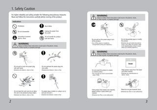
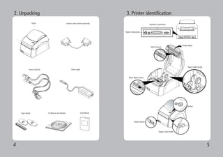

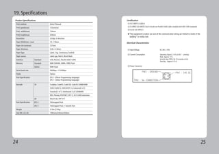
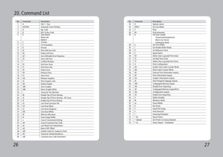

The document is a user manual for the LK-B30 desktop label printer, detailing its features, safety precautions, and operational instructions. It covers setup procedures, sensor configurations, media loading, and standard specifications for different types of printing media. The manual also provides a command list for various printer functions and maintenance guidelines.


