Heart Disease Prediction using machine learning.pptx
Fy 3208 h-en
1. 1
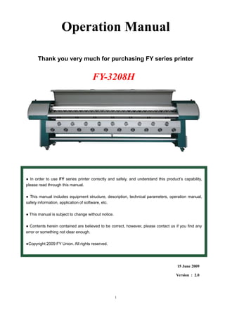
Operation Manual
Thank you very much for purchasing FY series printer
15 June 2009
Version : 2.0
● In order to use FY series printer correctly and safely, and understand this product’s capability,
please read through this manual.
● This manual includes equipment structure, description, technical parameters, operation manual,
safety information, application of software, etc.
● This manual is subject to change without notice.
● Contents herein contained are believed to be correct, however, please contact us if you find any
error or something not clear enough.
●Copyright 2009 FY Union. All rights reserved.
FY-3208H
3. 3
1.1 Important Safety Measures
Please read the following instructions before using the printer. Obey cautions and instructions
which are labeled on the printer.
Do NOT block the cover on the top of the printer.
Do NOT insert any object into the printing platform. Prevent spilling liquid onto the printer.
ONLY 220V can be applied.
Connect all the power cord to a single socket extension. Avoid sharing the socket with other
devices which will be on and off frequently.
Avoid using the socket with self-timer control and with the switch on the wall.
Keep a distance between any device which will release electro-magnetic field, such as wireless
phone.
Do NOT use damaged power cord.
If using an extra power cord, keep in mind that the total ampere of this device does not exceed
the assigned ampere of the power. Also, the total ampere of all the device which connect to
single socket cannot exceed the assigned ampere.
Do NOT try to repair the printer.
When encounter the following circumstance, disconnect the power and contact your local
distributor for support:
Power cord or plug is damaged;
Liquid is spilled onto the printer;
The printer fells down or the surface is broken;
Printer does not run normally.
Chapter 1 Safety Precaution
4. 4
1.2 Handling Printer Caution
Do NOT move the carriage when the power is on.
Always use the power switch to turn on or off the printer. Do NOT try to remove the data cable or
the power cord when the machine is on.
Make sure the carriage is stabilized in the origin position during transport.
Do NOT touch printing platform during printing.
1.3 Handling Ink Tank Caution
Please store ink tanks at the place where children cannot reach. Do NOT let children touch the
ink tank.
If ink is spilled into eyes, immediately wash with water and see your doctor.
Do NOT shake the ink tank, this may cause leakage.
Please often check the ink content in main ink tank, avoid unnecessary loss due to lack of ink.
Please often check the waste ink tank and replace it in time when it becomes full.
1.4 Printer Installation Site
Place the printer on a level floor otherwise it will not operate normally.
Avoid placing the printer in the area with huge change of temperature and humidity. Do NOT
expose the printer to direct sunlight or heat.
Avoid placing the printer in any possible shaking or vibrating area.
Leave enough space around the printer to ensure normal ventilation.
Place the printer close to the power socket so that power cord can be removed and plugged
easily.
Chapter 1 Safety Precaution
5. 5
2.1 Environment requirement
Keep the room temperature between 20—30℃, and the humidity between 40—60%. Air
conditioner and humidifier may require. Keep a distance from strong radiation field. The floor must be
level.
2.2 Electrical requirement
The printer only supports AC 220V. A transformer is needed if the area is using AC110V.
The printer must be well grounded ( the grounded voltage shouldn’t be more than 0.3V,
and the grounded resistance should be less than 4Ω ).
UPS and voltage stabilizer is highly recommended.
2.3 Computer requirement
1) Basic requirement:
CPU: 2.0 GHz or higher
Memory: 512 Mb or higher
Hard disk: 80 Gb (recommend 20Gb free space)
Mother board: PCI card slot
Network card
Operating system: Microsoft Windows (2000, XP)
2) Recommendatory requirement:
CPU: 3.0 GHz or higher
Memory: 1 Gb or higher
Hard disk: 200 Gb or higher (NTFS format)
Mother board: PCI card slot
Network card
Operating system: Microsoft Windows (2000, XP)
NOTICE: Suggest user format your hard disk into 2 partitions (NTFS). The first partition is used for
installing OS and other software, the second partition is used to save pictures and work files.
Chapter 2 Preparation and Procedures for Assembling
6. 6
2.4 Procedures of Assembling
1) Move the packing box to the working site and avoid strong shaking.
2) Disassemble the wooden packing box from top to bottom. Check whether the parts are
complete or not according to the packing list.
3) Lift the printer out by a forklift, and move it to the installation site.
4) Check if the printer is level.
5) Get rid of all the parts that stabilize the carriage holder, and install all the spare parts.
6) Move the carriage to the right of printer, then move back to the left manually. During this
process, check if there is abnormal resistance and carefully inspect the belt & the encoder
sensor are situated in proper position.
7) Ground the printer. The grounded voltage shouldn’t be more than 0.3V, and the grounded
resistance should be less than 4Ω .
8) Install the PCI card into the computer. Check if the wires and data cables are plugged in
properly.
9) Install the output and the rip software.
10) Turn on the printer, and keep your hand on the emergency button for turning off the printer
if problem happens suddenly.
11) Send a file to print to test the condition of the printer.
12) Clean the whole ink supply system with special solvent. Then empty the ink sub-tanks, and
repeat the step twice. At last, empty the remained solvent in the ink supply tubes through
ink sub-tanks.
13) Fill the main tank up with ink. Then empty the ink sub-tanks, and repeat the step twice, in
order to ensure there is no mixture of ink and solvent in the ink supply system.
14) Dip the aluminous caps in the solvent and clean them, in order to ensure no any sundries
exist.
15) Turn off the printer. Take the black washer out from the white cap on the top of the damper,
and then place the washer in the aluminous cap. (Figure 2-1) Stabilize the printhead with
screws. Connect the tube, and tighten the aluminous cap at the ink incoming part on the
top of the damper. Finally, connect the data cable.
Chapter 2 Preparation and Procedures for Assembling
7. 7
Figure 2-1
Attention A: When assemble the aluminous cap, you should screw on the aluminous
cap perpendicularly avoiding to damage the screw thread of the damper.
Attention B: When assemble new printhead, it’s unnecessary that you flush the
printhead additionally with solvent. It’s because there isn’t protective fluid in
printhead nozzles.
16) Fill the printhead with ink by using positive pressure, then wipe the ink droplet on the
surface of printhead plate with sponge stick.
17) Print nozzle checking and observe the condition of printheads. It is recommended to keep
a copy of the test for reference in the future.
18) Printhead alignment.
19) Start to Print.
Chapter 2 Preparation and Procedures for Assembling
Washer
8. 8
Machine Appearance
(1) (2) (3) (4) (5) (6) (7) (8)
(9) (10) (11) (12)
Cleaning Control
(13) Solvent Cleaning Switch
(14) Solvent Cleaning Switch
(15) Lighting Switch
(16) Individual Purging Switches
Individual Purging Switch:
“AF” is used to clean all
printheads. In addition, press
switches (13)+(14) together
to start solvent cleaning.
(1) Left Emergency Switch
(2) Bottom Left Machine box
(3) Cooling System
(4) Printing Platform
(5) Printing Beam
(6) Printing Cover
(7) Right Emergency Switch
(8) Bottom Right Machine Box
(9) Circuit Controlling Box
(10) Exhaust Emission
(11) Media Feeding Poles
(12) Top Left Machine Box
Chapter 3 Machine Structure and Accessories
(13) (14) (15) (16)
9. 9
Basic Operation
(17) Printhead Voltage Switch
(18) Media Suction Switch
(19) Media Take-up Switch
(20) Automatic or Manual Mode
(21) Turning Direction Switch
Media Feeding Button
(22) Media Feeding Switch
(23) Automatic or Manual Mode
(24) Turning Direction Switch
Main Power Controlling Area
(25) Optical Fiber Interface
(26) Heater Power Socket
(27) Heater Power Switch
(28) Rear Heater Controller
(29) Middle Heater Controller
(30) Front Heater Controller
(31) Heater Safety Switch
(32) Printer Safety Switch
(33) Printer Power Switch
(34) Printer Power Socket
(35) High Density Data Cable
Interface
( 17)
( 18)
( 19)
(20)
(21 )
( 22)
( 23)
( 24)
Chapter 3 Machine Structure and Accessories
( 31 )
( 32)
( 33)
( 34 )
( 35 )
( 25 )
( 26)
( 27 )
( 28 )
( 29 )
( 30 )
10. 10
Ink Supply System
(36) Solvent tube
(37) Air tube
(38) Air Pump
(39) K Sub-tank and Elec. Mag. Valve
(40) C Sub-tank and Elec. Mag. Valve
(41) M Sub-tank and Elec. Mag. Valve
(42) Safety Sub-tank
(43) Y Sub-tank and Elec. Mag. Valve
Attention: Only press the solvent cleaning buttons after connecting the solvent tube
with ink tube!
Attention: Empty the solvent tube after flushing. Cap both end of the solvent
tube to avoid dust contamination.
Chapter 3 Machine Structure and Accessories
( 36 ) ( 37 )
(43) (42) (41) (40) (39) (38)
11. 11
4.1 Characteristics
SPT 510_35pl printheads x 8;
Resolution: X direction 720360240 DPI;
Y direction 1080720360 DPI;
Colors:4 colors ;
Print mode:1,2,3,4,6,8,12,16 Pass;
Output mode:File or TCP/IP(Rip and Print at the same time);
Output preview:Convert prn/prt file into a small bmp file for previewing;
Print intelligently:Skip white area;
Setting of multi-printing;
Automatically flash jetting:Automatically clean printheads by flash jetting during printing;
Home flash jet: Prevent nozzles of printheads block while not in printing state;
Color bar:Prevent nozzles clogging, and observe nozzles status. Able to set the width of color
bar and the distance from image;
Able to align printheads, step difference ,and bi-direction difference;
Able to print uni-direction or bi-direction and mirror ;
Edge feather: Lighten pass line;
Cleaning System: Setting of auto-cleaning with Solvent;
Individual Positive Pressure Cleaning System: Clean with ink for each color, and avoid the
waste of ink;
Chapter 4 Basic Operation
12. 12
4.2. Installation for PCI card, Software of Driver
● Driver Installation
a) Insert PCI card into the PCI socket of the computer, then start the computer.
Attention: The PCI card can’t be inserted or drawn out while the computer is
in power on, otherwise the PCI card would be damaged.
b) After WINDOWS startup,it will search the driver for the PCI card automatically.
The setup will search the directory named “PCICardDriver” in Driver CD.
c) Connect Optical fibers:
There are two fiber wires with label “A” or “B” which connects from the PCI card to the
printhead board; therefore, these two boards come with the connection plug for the fiber wire.
The label “Tx” and “Rx” are indicated on the connection plug on the two boards. One of the
fiber wires connects to the “Tx”, and the other one connects to “Rx”. The optical fiber should
be plugged to the interface with aiming to the gap, then lock it.
Warning: Do NOT bend the optical fiber in an angle with less than 90 degree.
Optical
Fiber Interface
High Density Data
Cable Interface
A A
B B
TX
RX
RX
TX
Chapter 4 Basic Operation
13. 13
●Setup of Software
a) Enter the folder of “Printer V2.10 Printer V2.10(AC Motor)”. Run ePrinter.exe,the
following dialog box will show up:
b) Choose the Configuration file “SPT5108_35pl”.
c) Choose “OK”,PCI card and printhead card will execute reposition, the carriage will
return to home position. Choose “Do not anything”,will start software without
reposition.
Note:Normally choose “Reposition” when the software starts.
Note: Please uncheck “read only” in the property whenever the
“Printer” software is copied into the hard disk.
4.3 Introduction of Printing Controlling Software
a) Start the software and the main interface will show like the following picture:
Main Menu Common Function
Preview
File properties
Status Bar
Batch Files
File List
Chapter 4 Basic Operation
14. 14
Main
Menu
Submenu Function description
File
(F)
Open(O) Open the folder of the files which is available for printing, and
printing file will show up in the list
Refresh(F) Refresh the file list
Repreview(R) If the files in the folder is changed, you should press “Repreview”
to renew to list
Exit(X) Exit the software
Print
(P)
Home(H) Initialize PCI card, and the carriage return to home position
Measure(M) Measure the size of material(The function is currently unavailable)
Option(O) Enter “option” dialog box and set parameter
Preference(E) Based parameter setting, only used by engineer and client should
not change this parameter
Network Print(N) Activate this function; the software of printer will link to the rip
software. Jobs can be printed directly from rip software
Print(P) Print the file you choose, double click the file in file list, and
execute the operation
Stop(S) Stop current job and carriage return to home position
Pause(U) Pause current job and carriage return to home position
Continue(C) Continue current job
Functions
(U)
Cleaning Heads(W) Clean heads. In “option” dialog box you can set detail parameter
Purge Ink on/off(G) The function is currently unavailable
Cleaner on/off(L) The function is currently unavailable
Flush on/off(F) Turn on/off flush to prevent the nozzles block. In “option” dialog
box you can set flushing frequency
Heads
Temperature/Voltage(V)
Enter the dialog box of printhead voltage adjustment
Load Last Job(L) Resume the last unfinished Job
Move
(M)
Left(L) Move the carriage to left
Right(R) Move the carriage to right
Feeding(F) Move the material forward
Backward(B) Move the material backward
View
Tool Bar(T) Display/hide tool bar
Status bar(S) Display/hide status bar
Preview(P) Zoom in/out preview picture
Help
Help(H) The function is currently unavailable
About Printer(A)… Show version
Chapter 4 Basic Operation
15. 15
Common Parameter
Some frequent using functions are showing in the parameter bar:
a) Folder:The folder where the printed files is saved;
b) Pass: printing mode,1、2、3、4、6、8、12、16Pass;
c) Speed:Carriage moving speed while printing,the carriage can move with High, Middle
or Slow speed;
d) Copies: Number of copy of printing;
e) FirePos:Start printing position.(unit:mm)
f) Margin:The distance between the media edge and the cleaning position(unit:mm)
g) Move: The distance that carriage or media moves(unit:mm)
h) Test: Print test picture for modify offset parameter of printhead.
Parameter Setting
a) Print mode
Chapter 4 Basic Operation
16. 16
Print Mode
Pass Printing mode, 1、2、3、4、6、8、12、16Pass
XSpeed Carriage moving speed, High, Middle or Slow speed mode can be chosen
YSpeed Feed speed,High, Middle or Slow speed mode can be chosen
Qty Number of copy of every job
Horizontal mirror Print with horizontal mirror, used to print on double-face media.
Vertical mirror Image prints upside down
Smartprint Skip over white space in the picture
Edge Feather To blur the pass line,feather pass edge
Direction of
printing
Print to left/right
Unidirection Print only in one direction
Color bar
Prevent nozzles clogging, and keep track of the nozzle status. Able to set the width of color
bar and the distance from the picture
Enable Turn on/off color bar
Distance Distance between the color bar and the picture(unit:1 dot)
Width There are two values,one is the width of single color bar, another is the
width of mixed colors bar(unit:1 dot)
Position Set the color bar on the left/right of picture(unit:1 dot)
Disable at
beginning/ending
The color bar appears at the same height of the image
Cleaning
Cleaning Mode Flash jetting: Fire some ink out to keep nozzle open
Flash jetting
frequency
Amount of ink is going to fire. From 1/8 to 4k(Recommended flash jetting
frequency to be 4k for 3 minutes before starting printing. Flash jetting
frequency can be 32 for printhead of 12pl while printing. The changed flash
jetting frequency will be activated after doing the operation of “Home”).
Cleaning at home Cleaning when turning on the printer
Cleaning before
printing
Cleaning before printing
Cleaning during
printing
Freq: Set the interval of cleaning (unit: number of passes)
Times: Number of times of each cleaning
Flash during cleaning: Flash jetting during cleaning
Cleaning after
printing
Perform cleaning after printing
Flash jetting at
home
Flash jetting after reposition
Media
Print Position Starting printing position
Starting The left margin of media(unit:mm)
Width Width of media(unit:mm)
Margin The distance from the cleaning position to the left edge of the media (unit:
mm)
Chapter 4 Basic Operation
17. 17
b) Heads alignment
Heads
Quantity of
printhead
Number of printheads used in printing
Quantity of color Number of color: 4 colors
Quantity of
nozzle
Number of nozzles of every head
DPI of printhead The nozzle precision of one head
Step Difference Different value in different pass(unit:1/4 dot)
Bi-Difference Different Bi-Difference value in different speed(unit:2
dot)
Acceleration Length The time for the carriage to accelerate between passes
(unit:1 dot)
Color Offset There are three parameter every printhead(unit:1 dot)
To left The offset of printing to left,increase the value to add
offset,decrease the value to reduce offset
To right The offset of printing to right, increase the value to add
offset,decrease the value to reduce offset
Y direction The offset of Y direction
(The values can’t be negative)
The default parameters are adjusted in 360DPI. The software can automatically
distinguish from different rip resolutions, so it is unnecessary to select resolution
manually.
Chapter 4 Basic Operation
18. 18
Printhead voltage adjusting is like the following dialog box:
Automatic/manual voltage adjustment. Automatic adjustment when the box is checked.
After entering this dialog box under online mode, press “Update” to make the changed
parameters effective.
“Def. Volt” is the voltage value from the printhead. “Offset” modifies the “Def. Volt” to get the
final voltage. If “Enable Adjustment” is checked, the printheads voltage will be adjusted
automatically according to the temperature. The voltage will be fixed if this box is unchecked.
If clogging always happens on the same printhead, decrease the offset value only.
Chapter 4 Basic Operation
19. 19
Shortcut key
For convenient and fast operation,shortcut key is set.
a) Ctrl+Home “reposition”
b) Ctrl+End “cleaning”
c) Ctrl+Pause “Pause” and “continue”
d) Ctrl+← “move left”
e) Ctrl+→ “move right”
f) Ctrl+↑ “move back”
g) Ctrl+↓ “move forward”
4.4 Alignment Test
Adjust offset parameter through printing test-pictures:
4.4.1 Nozzles Checking
Observe nozzles status of each printhead. This is also the reference for printhead physical
adjustment.
Chapter 4 Basic Operation
20. 20
Printhead Physical Adjustment
1) Print the “Nozzles Checking” in uni-direction.
2) Adjust the angle of each printhead by observing whether lines between the first and second
pass are vertically connected. (Figure 4-2). If lines are not vertically connected (Figure 4-2-A),
adjust the angle of printhead with adjustor and make ensure the lines are vertically connected
(Figure 4-2-B).
A B
Figure 4-1 Figure 4-2
3) Adjust C1, M1, and Y1 vertically to be in line with K1 ( Figure 4-3).
Figure 4-3
Chapter 4 Basic Operation
21. 21
4) Adjust K2, C2, M2, Y2 to be interlude with K1, C1, M1, Y1 (Figure 4-4).
Figure 4-4
● Printhead Physical position will have to be adjusted well due to it affects the printing
resolution.
4.4.2 Heads Alignment
Figure 4-5
Adjust offset of every printhead according to the printed “Heads Alignment” (Figure 4-5). The
black-head is the reference, so the value of black-head should be set to zero.
The Procedure of Adjustment
1) Print the “Heads Alignment” (Figure 4-5);
2) Enter “OptionHeads AlignmentColorOffset” (Figure 4-6);
Figure 4-6
Chapter 4 Basic Operation
22. 22
3) XTR (X to Right): Find the line which is horizontally well fit into the black line
4) XTL (X to Left): Find the line which is horizontally well fit into the black line.
5) YOS (Y Position): Find the line which is vertically well fit into the black line.
The indicated value in the color circle need to input into the color offset, and the parameters are
accumulated. Repeat the above steps until the line at “0” well fit into the black line.
4.4.3 Step Adjustment
Print two lines with different PASS and adjust step offset. The thinner the lines are, the better the
step is.
4.4.4 Full Colors
Print a solid block with all colors.
Chapter 4 Basic Operation
23. 23
5.1 Normal Cleaning
Positive Pressure Cleaning
Press the cleaning button, and then use sponge stick or soft fabric to wipe the surface of the
printhead.
Warning: Using the material other than sponge stick or soft fabric to wipe the
printhead may risk damaging nozzles.
5.2 Cleaning procedures for nozzle clogging
Ⅰ. Disconnect the tube connector for the tube from the Subtank to the printhead.
Wait until the ink finishes dropping almost, and then, connect the tube to the
solvent tube. Press both of the flush buttons to clean the printhead with
solvent. Stop until the solvent becomes clear nearly.
Ⅱ. Use tube cover to seal the ink incoming tube for the printhead. Use fresh
wrap to cover the nozzle surface. Leave it for 12 hours.
Ⅲ. Take the fresh wrap off. Disconnect the tube cover and wait until the
solvent is removed almost. Connect the tube to the subtank, and fill the
printhead with ink.
The condition of printhead should be improved after performing the above
cleaning procedures.
5.3 Carriage Bearing and Steel Rail Maintenance
Due to the carriage slides on four steel plates and eight bearing, clean and
lubricate four steel plates with grease everyday.
Ⅰ. Wipe a thin layer of grease on steel plates to maintain cleanliness and grease
everyday before and after usage.
Ⅱ. Be aware of the smoothness of the carriage bearing
Figure 5-1
Chapter 5 Maintenance Guide
24. 24
5.4 Daily maintenance
1) Please print the “Nozzles Checking” to make sure all the nozzles are firing fine before switching
off the printer. Then switch off the printer.
2) Prepare special solvent, PE wrap film(width: 30cm), nonwoven fabric(7cm x 2cm) (Figure 5-2).
Figure 5-2
3) Push the carriage to the right for leaving the cleaning position(Figure 5-3), then place the capping
cover on the waste ink trough correctly(Figure 5-4).
Figure 5-3 Figure 5-4
4) Cut a piece of PE wrap film into 60cm long, then place it on the capping cover and level it off.
Place the nonwoven fabric dipped the solvent on each cap of the capping cover(Figure 5-5), then
push the carriage back to the cleaning position(Figure 5-6).
Figure 5-5 Figure 5-6
Chapter 5 Maintenance Guide
25. 25
5) At last, push the carriage all the way to the left to seal printheads by the PE wrap film and capping
cover perfectly(Figure 5-7). The nonwoven fabric and PE wrap film have to be changed everyday
Figure 5-7
Please move the capping cover away before turning on the printer.
5.5 Short term shut down (3~7 days)
1)Disconnect the tube connector for the tube from the Subtank to the printhead. Wait until the
ink finishes dropping, and then, connect the tube to the solvent tube. Press both of the flush
buttons to clean the printhead with solvent. Stop until the solvent becomes clear nearly.
2)Use tube cover to seal the ink incoming tube for the printhead. Use fresh wrap to cover the
nozzle surface. Then, push the carriage all the way to the left to seal printheads by the cap.
5.6 Long term shut down (More than a week)
1) Clean the whole ink supply system by solvent.
2) Disconnect the tube connector for the tube from the Subtank to the printhead. Wait until the
solvent finishes dropping almost. Use tube cover to seal the ink incoming tube for the
printhead. Use fresh wrap to cover the nozzle surface. Then, push the carriage all the way
to the left to seal printheads by the cap.
Attention:For keeping the ink supply system clean, please replace the filter every 4 months.
Chapter 5 Maintenance Guide
26. 26
5.7 Cleaning procedures for nozzle clogging
1) Disconnect the tube connector for the tube from the Subtank to the printhead.
Wait until the ink finishes dropping almost, and then, connect the tube to the
solvent tube. Press both of the flush buttons to clean the printhead with
solvent. Stop when the solvent becomes clear.
2) Use tube cover to seal the ink incoming tube for the printhead. Use fresh
wrap to cover the nozzle surface. Leave it for 12 hours.
3) Take the fresh wrap off. Disconnect the tube cover and wait until the solvent
is removed almost. Connect the tube to the subtank, and fill the printhead
with ink.
When printhead needed to be taken out for maintenance, there are long-term and
short-term maintenance. Short-term is within one month, and long term is within
two months. After two months, printhead need to be installed to the printer and
check the nozzle firing again. Maintain the printhead again after checking. Please
refer to the following procedure for used printhead short term and long term
storage maintenance.
The storage condition is shown in the following:
a) Room temp: 5 - 40 ℃
b) Humidity: 10- 85%
c) Prevent direct sunlight
5.8 Used printhead short term storage maintenance
Clean the printhead with solvent, and leave some solvent in the printhead.
Remove the printhead together with the tube. Place the non-woven fabric, which
is already submerged into solvent, onto the nozzle plate. Wrap the printhead by
cling film. Install the printhead onto the original base.
5.9 Long term used printhead storage maintenance (SPT510-35pl)
5.9.1 Clean the printhead by solvent.
5.9.2 Empty the solvent in the printhead.
5.9.3 Wipe the solvent surrounding the printhead by non-woven fabric. Do not
scratch the nozzle plate.
Chapter 5 Maintenance Guide
27. 27
Step 1 Step 2 Step 3
Step 4 Step 5 Step 6
Step 7 Step 8 Step 9
Step 10 Step 11
Chapter 5 Maintenance Guide
Put the plastic box into the
paper box
Install the printehad stand.Wrap the film on the top of
the printhead.
Wrap the printhead from the edge of the
film. Pull the film tightly to seal the
printhead as much as possible
Seal the printhead on both
sides.
Gently remove the air between the
film and the surface of nozzles.
Wrap the surface of the nozzle
by the cling film.。
Cut the cling film into a piece about 30cm
x 30cm. Do not make the film wrinkle.
Tighten the cap. Make sure
the washer is in place.
Cap
Cling
Film
Make sure
there are no
bubbles and
wrinkles.
Stand
Put the printhead into the
orginal plastic box.
Caution:
(1)Remove the remaining solvent in the printhead
totally.
(2)Tighten the cap properly:
If the washer is in the proper position, the cap
can be tighten easily.
Do not force to tighten the cap when the position
of the washer is not proper.
(3)Wrap the printhead carefully.
If the above retuning procedures are not followed,
and the test cannot be performed due to the spilling
ink or solvent, the factory is not going to take any
responsibility.
28. 28
6.1 Printhead not firing ink
Check whether printhead voltage is on.
Check whether optical fiber connects correctly.
Check whether the reading of the encoder in the software is changing when the carriage is moving.(If
reading does not increase or decrease correspondingly, check the encoder sensor).
6.2 Carriage motor (X motor) not functioning
Check whether PCI card is installed properly.
Check whether motor is under self-lock with electricity.
Refer to the motor servo driver in the circuit diagram for the connections. Check whether the power and
data cable are connecting correctly.
6.3 Feeding motor (Y motor) not functioning
Procedures are the same as 6.2.
6.4 Feeding or take-up motor not functioning
Check the sensitivity of the sensor.
Replace the feeding and take-up board.
Replace the feeding or take-up sensor.
6.5 X or Y motor overheated (The surface of the motor exceeds 50 degree Celsius)
Check whether there is resistance when moving the carriage. If there is obvious resistance, check if the
motor gear is in the proper position. The gear should not have contact with the motor.
6.6 The parameter of printhead voltage is not correct when uploading or downloading
Check whether the driver of the PCI card is installed.
Check whether optical fiber connects correctly.
Check whether no damage on the optical fiber.
Change computer and PCI card.
Change printhead board.
6.7 Software froze or parameter cannot be saved
Replace the “printer” software from the CD.
“Printer” software requires all the files to be writable. Uncheck the “Only for read” under the properties.
6.8 Miss color during printing
Check whether there is air in the printhead and tube between ink sub-tank and printhead. If there is,
please remove it.
Check whether no air leakage.
Set proper printhead voltage.
Check whether negative pressure is correct by adjusting the sub-tank height.
6.9 Ink supply system not functioning
Reconnect long flat data cable of “S” and check whether the connection part is not damaged.
Check whether ink pump connects properly.
Change servo board.
Check whether floating switch is working properly.
6.10 Pump is not working
Check whether there is the incoming voltage of 24V.
Check whether the plug is connected properly.
Chapter 6 Troubleshoot
29. 29
Use syringe to inject and suck out air from the ink incoming side. Stop until you feel the piston is
moving.
Check whether there is ink in the safety sub-tank. If there is, please empty the safety sub-tank.
Change pump.
6.11 Ink drops out from the printhead after positive pressure cleaning
Check whether air tube is clipped.
Check whether elec. mag. valve is clogged by ink, If it is, please clean it with solvent. Or change elec.
mag. Valve.
6.12 Interruption during printing
Restart the printer and the computer.
Rip the image again.
Check optical fiber connection.
Replace “Printer” software.
Change PCI card.
Change printhead board.
6.13 Printer froze or bi-direction changes to uni-direction, carriage hitting the frame, and haves data
error
Check whether long and short belts of the carriage movement are vibrating.
Check the consistence between motor gear and motor.
Check whether raster strip is dirty or encoder sensor is damaged.
Change motor.
6.14Vertical banding
Clean and lubricate 4 steel rails with grease perfectly or change the carriage bearing.
Chapter 6 Troubleshoot
30. 30
Specification
Model FY-3208H
FY-252C
FY-212C
FY-182C
Printhead SPT510-35PL
Number of printhead 8, 4 Heads
Max. printing width 3200mm
Max. media width 3250mm
Output Quantity
Printing Mode Output(m2
/h)
360x360 1 pass 101
240x720 2 pass 76
240x1080 3 pass 51
360x1080 3 pass 34
720x720 4 pass 26
Ink
Type Solvent
Color (C,M,Y,K)
Volume 1 liter or 5 liters main tank
Ink supply system Ink level sensor. Auto-pumping
Media PVC banner, vinyl, film, polyester, etc
Feeding System Roll or sheet(Max. weight: 120kg)
Ph. Cleaning System Positive pressure cleaning. Anti-clogged flash function. Capping system.
Heating System Pre-heater and front heater control. Max. 80
0
C
Clamp Equipped
Data Transfer Optical fiber
Printhead height Adjustable distance from 2mm~4mm.
RIP PhotoPrint, Maintop , UltraPrint , Topaz , Wasatch , Caldera
Input Voltage AC220V,50Hz/60Hz
Printer Dimension/Weight L4600xW820xH1320mm / 389KG
Package Dimension/Weight L4630xW1050xH920mm / 589KG
*The speed data are taken from the printer at the high speed level, there are tolerance in different computers.
~ End ~
Chapter 7 Technical Specification