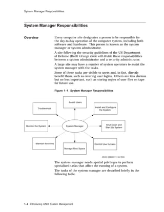
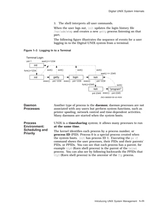
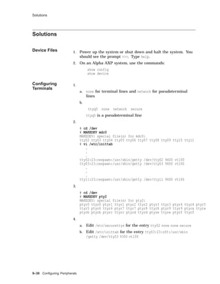
This document provides an overview of Digital UNIX system administration and managing disks and file systems. It describes the responsibilities of a system manager, the UNIX software environment including the kernel and features of Digital UNIX. It discusses system internals such as process creation, scheduling, and memory management. It also covers superuser privileges, the root login procedure, and using the Common Desktop Environment for administration tasks. Regarding disk and file system management, it details disk drive structure, logical volumes, partitions, file systems, and using tools like disktab to derive disk parameters.


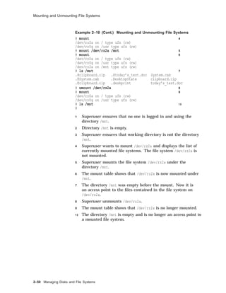
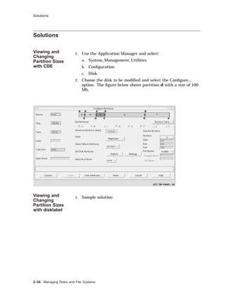
![About This Course
Course
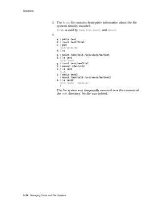
Conventions
Table 1 gives an explanation of the conventions used in this
course.
Table 1 Conventions Used in This Course
Convention Meaning
keyword Keywords and new concepts are displayed in this
type.
examples Examples, commands, options and pathnames
appear in this type.
command(x) Cross-references to command documentation
include the section number in the reference
pages. For example, fstab(5) means fstab is
referenced in Section 5.
$ A dollar sign represents the user prompt.
# A number sign represents the superuser prompt.
bold Within interactive examples, boldface type
indicates user input.
key The box symbol indicates that the named key on
the keyboard is pressed.
.
.
.
In examples, a vertical ellipsis indicates that not
all of the lines of the example are shown.
[ ] In syntax descriptions, brackets indicate items
that are optional.
variable In syntax descriptions, this type indicates items
that are variable.
.
.
.
In syntax descriptions, an ellipsis indicates the
item may be repeated.
xxvi](https://image.slidesharecdn.com/dunix-141227095156-conversion-gate02/85/Dunix-sys-operating-26-320.jpg)

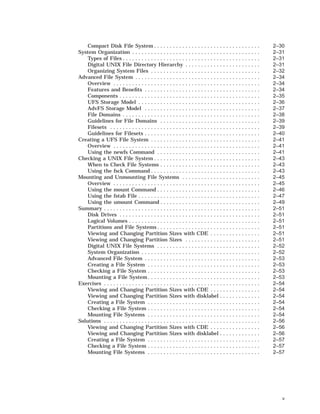
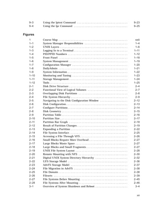
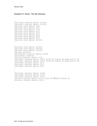
![Partitions and File Systems
Partition Offset Size (sectors)
Block Size
(bytes)
Fragment
Size (bytes)
d 393216 301986 8192 1024
e 695202 301986 8192 1024
f 997188 301986 8192 1024
g 393216 819200 8192 1024
h 1212416 86758 8192 1024
For more information on any type of disk, see that type in the
Reference Pages; for example, rz(7).
The following example shows a section of an /etc/disktab file.
Example 2–2 An /etc/disktab File
# Disk geometry and partition layout tables.
# Key:
# ty type of disk
# dt drive type (SCSI MSCP etc.)
# ns #sectors/track
# nt #tracks/cylinder
# nc #cylinders/disk
# o[a-h] partition offset
# P[a-h] partition sizes in sectors
# b[a-h] partition block sizes in bytes
# f[a-h] partition fragment sizes in bytes
rz56|RZ56|DEC RZ56 Winchester:
:ty=Winchester:dt=SCSI:ns#54:nt#15:nc#1632:
:oa#0:pa#131072:ba#8192:fa#1024:
:ob#131072:pb#262144:bb#8192:fb#1024:
:oc#0:pc#1299174:bc#8192:fc#1024:
:od#393216:pd#301986:bd#8192:fd#1024:
:oe#695202:pe#301986:be#8192:fe#1024:
:of#997188:pf#301986:bf#8192:ff#1024:
:og#393216:pg#819200:bg#8192:fg#1024:
:oh#1212416:ph#86758:bh#8192:fh#1024:
Managing Disks and File Systems 2–11](https://image.slidesharecdn.com/dunix-141227095156-conversion-gate02/85/Dunix-sys-operating-69-320.jpg)
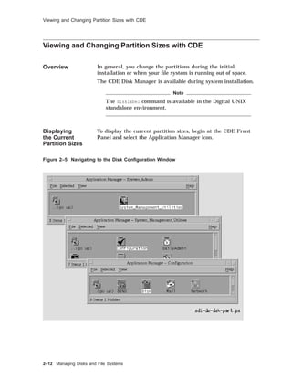
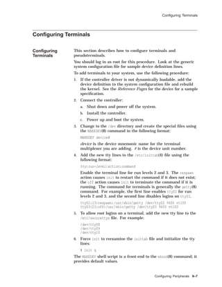
![Viewing and Changing Partition Sizes
Viewing and Changing Partition Sizes
Overview In general, you change the partitions during the initial
installation or when your file system is running out of space.
The disklabel command is available in the Digital UNIX
standalone environment. You must have superuser privileges to
use the disklabel command.
The partition size and offset are in 512-byte sectors. The offset is
the starting sector number for the partition.
To display the current partition sizes, use disklabel -r with the
raw device name for partition a or c. The example shows how to
display a disk label.
Example 2–3 Displaying the Disk Label
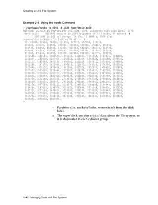
# disklabel -r /dev/rrz0a
# /dev/rrz0a:
type: SCSI 1
disk: rz55 2
label: 3
flags: 4
bytes/sector: 512 5
sectors/track: 36
tracks/cylinder: 15
sectors/cylinder: 540
cylinders: 1224
rpm: 3600 6
interleave: 1
trackskew: 0
cylinderskew: 0
headswitch: 0 # milliseconds
track-to-track seek: 0 # milliseconds
drivedata: 0 7
7 partitions: 8
# size offset fstype [fsize bsize cpg]
a: 40960 0 4.2BSD 1024 8192 16 # (Cyl. 0 - 75*)
b: 122880 40960 4.2BSD 1024 8192 16 # (Cyl. 75*- 303*)
c: 649040 0 unused 1024 8192 # (Cyl. 0 - 1201*)
d: 152446 163840 unused 1024 8192 # (Cyl. 303*- 585*)
e: 152446 316286 unused 1024 8192 # (Cyl. 585*- 868*)
f: 180308 468732 unused 1024 8192 # (Cyl. 868*- 1201*)
g: 485200 163840 4.2BSD 1024 8192 16 # (Cyl. 303*- 1201*)
#
1 Controller type; for example, SCSI, ESDI, SMD, MSCP
2 Disk type name
3 Optional label
4 Flags; for example, removable, RAMDISK, ECC
5 Disk geometry section
2–20 Managing Disks and File Systems](https://image.slidesharecdn.com/dunix-141227095156-conversion-gate02/85/Dunix-sys-operating-78-320.jpg)
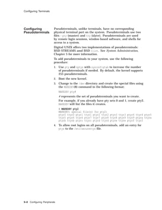
![Viewing and Changing Partition Sizes
Example 2–4 Expanding a Partition
# /sbin/disklabel -r /dev/rrz2a
# /dev/rrz2a:
type: SCSI
disk: rz23
label:
.
.
.
8 partitions:
# size offset fstype [fsize bsize cpg]
a: 40960 0 unused 1024 8192 # (Cyl. 0 - 155*)
b: 58498 40960 unused 1024 8192 # (Cyl. 155*- 376*)
c: 204864 0 unused 1024 8192 # (Cyl. 0 - 775)
d: 35135 99458 unused 1024 8192 # (Cyl. 376*- 509*)
e: 35135 134593 unused 1024 8192 # (Cyl. 509*- 642*)
f: 35136 169728 unused 1024 8192 # (Cyl. 642*- 775*)
g: 105406 99458 unused 1024 8192 # (Cyl. 376*- 775*)
h: 70271 134593 unused 1024 8192 # (Cyl. 509*- 775*)
# /sbin/disklabel -e -r /dev/rrz2a
(invokes an editor; we change partition a size from 40960 to 99458)
type: SCSI
disk: rz23
label:
flags:
bytes/sector: 512
sectors/track: 33
tracks/cylinder: 8
sectors/cylinder: 264
cylinders: 776
rpm: 3600
interleave: 1
trackskew: 0
cylinderskew: 0
headswitch: 0 # milliseconds
track-to-track seek: 0 # milliseconds
drivedata: 0
8 partitions:
# size offset fstype [fsize bsize cpg]
a: 99458 0 unused 1024 8192 # (Cyl. 0 - 155*)
b: 58498 40960 unused 1024 8192 # (Cyl. 155*- 376*)
c: 204864 0 unused 1024 8192 # (Cyl. 0 - 775)
d: 35135 99458 unused 1024 8192 # (Cyl. 376*- 509*)
e: 35135 134593 unused 1024 8192 # (Cyl. 509*- 642*)
f: 35136 169728 unused 1024 8192 # (Cyl. 642*- 775*)
g: 105406 99458 unused 1024 8192 # (Cyl. 376*- 775*)
h: 70271 134593 unused 1024 8192 # (Cyl. 509*- 775*)
~
(when you exit the editor, you will be prompted)
write new label? [y]: Return
(continued on next page)
Managing Disks and File Systems 2–23](https://image.slidesharecdn.com/dunix-141227095156-conversion-gate02/85/Dunix-sys-operating-81-320.jpg)
![Viewing and Changing Partition Sizes
Example 2–4 (Cont.) Expanding a Partition
# /sbin/disklabel -r /dev/rrz2a
# /dev/rrz2a:
type: SCSI
disk: rz23
label:
.
.
.
8 partitions:
# size offset fstype [fsize bsize cpg]
a: 99458 0 unused 1024 8192 # (Cyl. 0 - 376*)
b: 58498 40960 unused 1024 8192 # (Cyl. 155*- 376*)
c: 204864 0 unused 1024 8192 # (Cyl. 0 - 775)
d: 35135 99458 unused 1024 8192 # (Cyl. 376*- 509*)
e: 35135 134593 unused 1024 8192 # (Cyl. 509*- 642*)
f: 35136 169728 unused 1024 8192 # (Cyl. 642*- 775*)
g: 105406 99458 unused 1024 8192 # (Cyl. 376*- 775*)
h: 70271 134593 unused 1024 8192 # (Cyl. 509*- 775*)
We can display the disk label again, showing the changes we have
made. Notice the cylinder numbers for partition a have been
automatically updated.
Repartitioning
a Disk
The following are suggestions for repartitioning a disk.
• Increase a partition if a file system or swap area is running
out of space.
• To make backups easier, size partitions based on your backup
device’s storage capacity.
• Create separate file systems on separate disks for /, /usr, var,
and users’ home directories to improve performance and make
backups easier.
• Divide swap space between two partitions on different disks to
improve performance.
2–24 Managing Disks and File Systems](https://image.slidesharecdn.com/dunix-141227095156-conversion-gate02/85/Dunix-sys-operating-82-320.jpg)
![Creating a UFS File System
Creating a UFS File System
Overview You do not need to create the root and /usr file systems before
installing the system; these are created as part of the installation.
If you want separate file systems for users’ home directories,
layered products, or other files, you must create these file systems
after the installation.
Using the
newfs
Command
When you have a new partition or logical volume, you must
prepare it to hold files by creating a file system.
To create a new file system, use the newfs(8) command.
newfs [ -N ] [ options ] device type
-N Displays file system parameters without creating a file
system.
options Options depend on the type of file system; for example,
for UFS you can specify the size in sectors or the
number of bytes per inode. See newfs(8) for more
options.
device The unmounted, raw device name; for example, /dev
/rrz1a.
type The disk type from /etc/disktab.
You must be root to use newfs.
The newfs command destroys all data on an existing file system.
The following example shows how to create a UFS file system
with a block size of 8192 bytes and fragment size of 1024 bytes on
partition c of an RZ28 disk, which is drive 1.
Managing Disks and File Systems 2–41](https://image.slidesharecdn.com/dunix-141227095156-conversion-gate02/85/Dunix-sys-operating-99-320.jpg)
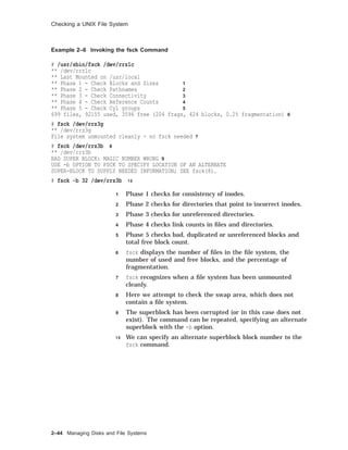
![Checking a UNIX File System
Checking a UNIX File System
When to Check
File Systems
File systems are checked automatically when the system starts.
You should check a file system before mounting it manually or
backing it up.
Using the fsck
Command
Use the fsck(8) command to check a UNIX file system. Advanced
file systems and network file systems do not need to be checked.
The fsck command looks for and corrects inconsistencies such as:
• Unreferenced inodes
• Link count number in inode is too large
• Missing blocks in the free list
• Blocks in the free list that are also in files, or blocks that are
in two files
• Incorrect counts in the superblock
fsck [ options ] [ filesystem ]
options Some options for UFS file systems:
-p Checks and corrects a set of
inconsistencies. If it encounters other
errors, it exits.
Without the -p option, fsck works
interactively, prompting before each
correction.
-b block Specifies the block to use as the
superblock. (Block 32 is usually used
as alternate superblock.)
-y Assumes a yes response to all prompts.
-n Assumes a no response to all prompts.
filesystem The raw device name for the file system you want
checked; for example, /dev/rrz1a. If you do not specify
a file system, all file systems in /etc/fstab are checked.
Orphaned files are put in the lost+found directory, using the inode
as a name. If the lost+found directory does not exist, you can
create it with the mklost+found(8) command. If you choose not
to create it, it will be created automatically if orphaned files are
found.
You must be root to use fsck.
Check file systems when they are unmounted. Since the root file
system cannot be unmounted, check it in single-user mode. This
will prevent fsck reporting and attempting to fix inconsistencies
due to normal system operations. Example 2–6 shows how to
invoke the fsck command.
Managing Disks and File Systems 2–43](https://image.slidesharecdn.com/dunix-141227095156-conversion-gate02/85/Dunix-sys-operating-101-320.jpg)
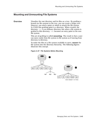
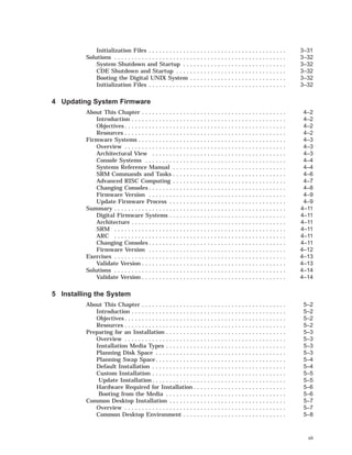
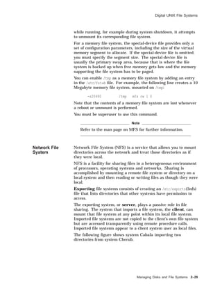
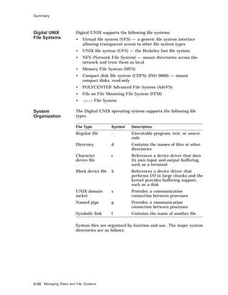
![Mounting and Unmounting File Systems
Figure 2–28 File Systems After Mounting
/
dev etc sbin tmp usr
file1 file2 file3
bin lib sbin share sys
ZKOX−055000111−08−RGS
1
2
Disk 1 is the system disk containing the root file system. Disk 2
is another disk containing a file system. Before it is mounted, the
files on it are not accessible.
Once it is mounted, the files are accessible through the directory
mount point, in this case /usr.
This figure illustrates another important point. Usually you
will not mount a file system on a directory that contains files.
However, you can do so without deleting or damaging the files.
The files will be invisible and inaccessible until the file system is
unmounted.
The mount command is available in the Digital UNIX standalone
environment.
The root file system is mounted automatically when the system is
booted, and cannot be unmounted.
Using the
mount
Command
To mount a file system under an existing directory, use mount.
mount [ options ] [ device ] [ mountpoint ]
options Some options include:
-a Mounts all file systems listed in /etc
/fstab
-t Specifies a type of file system to mount;
for example
# mount -a -t ufs
-r Specifies mount with read-only access
-o Specifies file system specific options
device The special device name
mountpoint The existing directory to mount the file system
under
2–46 Managing Disks and File Systems](https://image.slidesharecdn.com/dunix-141227095156-conversion-gate02/85/Dunix-sys-operating-104-320.jpg)
![Mounting and Unmounting File Systems
Using the
umount
Command
Use the umount command to unmount a file system. The format
for umount is:
umount [ options ] [ mountpoint ]
options Some options include:
-A Attempts to unmount all file systems
currently mounted
-a Unmounts all file systems listed in /etc
/fstab
-t Specifies a type of file system to unmount;
for example
# umount -a -t ufs
-h Specifies a host for unmounting all file
systems remotely mounted in /etc/fstab.
mountpoint The existing directory where the file system is
mounted
You must unmount a file system if you want to check it with fsck
or change its partition size with disklabel.
You cannot unmount a file system if one of the files or directories
is in use.
You cannot unmount the root file system. Example 2–9 shows
how to use the umount command.
Example 2–9 Using the umount Command
# mount
/dev/rz0a on / type ufs (rw)
/dev/rz0g on /usr type ufs (rw)
/dev/rz0h on /usr/users type ufs (rw)
/dev/rz1c on /usr/local type ufs (ro)
/usr/share/man@tinker on /usr/share/man type nfs (ro,bg,soft,nosuid)
# umount /usr/local
# umount /usr
umount /dev/rz0g: Mount device busy
# umount -h tinker
The following example shows the mount and umount commands.
Example 2–10 Mounting and Unmounting File Systems
# who 1
superman tty00 Apr 29 13:57
# ls /mnt 2
# pwd 3
/
(continued on next page)
Managing Disks and File Systems 2–49](https://image.slidesharecdn.com/dunix-141227095156-conversion-gate02/85/Dunix-sys-operating-107-320.jpg)
![Solutions
# disklabel -r /dev/rrz0a
# /dev/rrz0a:
type: SCSI
disk: rz55
label:
flags:
bytes/sector: 512
sectors/track: 36
tracks/cylinder: 15
sectors/cylinder: 540
cylinders: 1224
rpm: 3600
interleave: 1
trackskew: 0
cylinderskew: 0
headswitch: 0 # milliseconds
track-to-track seek: 0 # milliseconds
drivedata: 0
7 partitions:
# size offset fstype [fsize bsize cpg]
a: 40960 0 unused 1024 8192 # (Cyl. 0 - 75*)
b: 122880 40960 unused 1024 8192 # (Cyl. 75*- 303*)
c: 649040 0 unused 1024 8192 # (Cyl. 0 - 1201*)
d: 152446 163840 unused 1024 8192 # (Cyl. 303*- 585*)
e: 152446 316286 unused 1024 8192 # (Cyl. 585*- 868*)
f: 180308 468732 unused 1024 8192 # (Cyl. 868*- 1201*)
g: 485200 163840 4.2BSD 1024 8192 16 # (Cyl. 303*- 1201*)
#
2. Editing the disk label without the -r option affects only the
copy in memory, not the label on the disk.
3. Displaying the disk label should show your changes: for
partition d, increase the size by 1000 but not the offset; if
partition e is adjacent to d, increase e’s offset by 1000 and
decrease its size by 1000. Add the disk name after the label:
field.
Creating a File
System
1. No solution required.
2. # newfs /dev/rrz1g RZ56
Checking a File
System
1. No solution required.
2. # fsck /dev/rrz1g
3. # fsck -y /dev/rrz1g
Mounting File
Systems
1. No solution required.
2. Solution varies.
# mount
/dev/rz0a on / type ufs (rw)
/dev/rz0g on /usr type ufs (rw)
/dev/rz0h on /usr/users type ufs (rw)
/dev/rz1c on /usr/local type ufs (ro)
Managing Disks and File Systems 2–57](https://image.slidesharecdn.com/dunix-141227095156-conversion-gate02/85/Dunix-sys-operating-115-320.jpg)
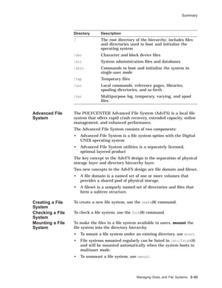
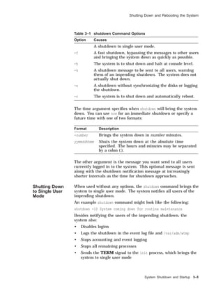
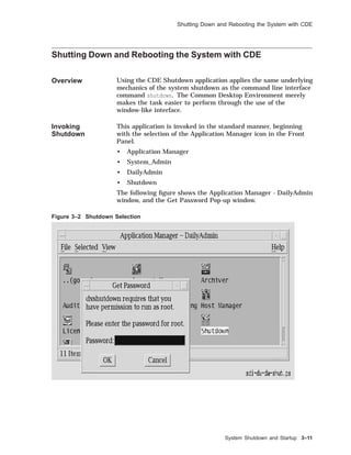
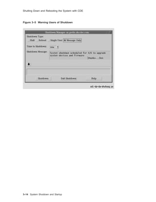
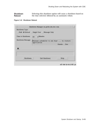
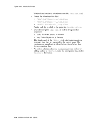
![Shutting Down and Rebooting the System
Methods
for System
Shutdown
There are a number of ways you can shut down and reboot your
UNIX system.
• Use the:
CDE Shutdown manager
shutdown command
halt or fasthalt command
init command
• Send a signal to the init process.
• Turn off the power.
Figure 3–1 provides an overview of various commands used to
shut down or reboot a UNIX system.
Figure 3–1 Overview of System Shutdown and Reboot
#
>>>
>>>
halt, fasthalt
ZKOX−055000111−09−RGS
reboot
shutdown −r, reboot
shutdown −h, init 0
shutdown, init s
Halt
Mode
Single
User
Mode
Multiuser
Mode
Using the
shutdown
Command
Use the shutdown command to halt, reboot, or return to single user
mode. The command provides the most consideration for other
users. You must be logged in as root to execute this command.
The format for the shutdown command is:
shutdown [-fhknr] time [warning-message]
The shutdown options are shown in Table 3–1.
3–4 System Shutdown and Startup](https://image.slidesharecdn.com/dunix-141227095156-conversion-gate02/85/Dunix-sys-operating-120-320.jpg)
![Shutting Down and Rebooting the System
Shutdown is complete when the system console displays single
user mode.
INIT: SINGLE USER MODE
#
You have superuser access to the system through the console,
using the Bourne shell to perform administrative tasks.
Prior to the transition from multiuser to single user mode, the
output from the process status (ps -aef) command might look like
the one shown in Example 3–1.
Example 3–1 Typical Multiuser Mode ps Output
UID PID PPID C STIME TTY TIME CMD
root 0 0 1.5 Aug 19 ?? 04:51:51 [kernel idle]
root 1 0 0.0 Aug 19 ?? 0:00.39 /sbin/init -sa
root 3 1 0.0 Aug 19 ?? 0:00.42 /sbin/kloadsrv
root 40 1 0.0 Aug 19 ?? 1:54.21 /sbin/update
root 113 1 0.0 Aug 19 ?? 0:01.15 /usr/sbin/syslogd
root 115 1 0.0 Aug 19 ?? 0:00.01 /usr/sbin/binlogd
root 177 1 0.0 Aug 19 ?? 0:53.15 /usr/sbin/routed -q
root 309 1 0.0 Aug 19 ?? 0:00.55 /usr/sbin/portmap
root 311 1 0.0 Aug 19 ?? 0:00.11 /usr/sbin/mountd -i
root 313 1 0.0 Aug 19 ?? 0:00.02 /usr/sbin/nfsd -t8 -u8
root 315 1 0.0 Aug 19 ?? 0:00.01 /usr/sbin/nfsiod 7
root 318 1 0.0 Aug 19 ?? 0:00.02 /usr/sbin/rpc.statd
root 320 1 0.0 Aug 19 ?? 0:00.05 /usr/sbin/rpc.lockd
root 346 1 0.0 Aug 19 ?? 0:00.03 /usr/sbin/dnalimd
root 349 346 0.0 Aug 19 ?? 0:05.28 /usr/sbin/dnaevld
root 381 346 0.0 Aug 19 ?? 3:01.33 /usr/sbin/dnascd
root 382 381 0.0 Aug 19 ?? 0:00.10 /usr/sbin/dnansd
root 383 381 0.0 Aug 19 ?? 0:00.37 /usr/sbin/dnaksd
root 387 346 0.0 Aug 19 ?? 0:10.55 /usr/sbin/dnsadv
root 429 1 0.0 Aug 19 ?? 0:03.10 /usr/sbin/dtssd
root 433 387 0.0 Aug 19 ?? 0:00.21 /usr/sbin/dnsclerk -U r
root 435 346 0.0 Aug 19 ?? 0:00.07 /usr/sbin/dnanoded
root 482 1 0.0 Aug 19 ?? 0:00.37 /usr/sbin/osaknmd
root 522 1 0.0 Aug 19 ?? 0:14.64 -accepting connections
root 542 1 0.0 Aug 19 ?? 0:03.79 /usr/sbin/xntpd -g -x -
root 576 1 0.0 Aug 19 ?? 0:04.26 /usr/sbin/os_mibs
root 579 1 0.0 Aug 19 ?? 1:37.92 /usr/sbin/snmpd
root 581 1 0.0 Aug 19 ?? 28:48.23 /usr/sbin/advfsd
root 592 1 0.0 Aug 19 ?? 0:00.17 /usr/sbin/inetd
root 625 1 0.0 Aug 19 ?? 0:00.60 /usr/sbin/cron
root 657 1 0.0 Aug 19 ?? 0:00.20 /usr/lbin/lpd
root 676 1 0.0 Aug 19 ?? 0:00.12 /usr/bin/mmeserver -con
root 690 1 0.0 Aug 19 ?? 0:00.49 /usr/dt/bin/dtlogin -da
root 702 1 0.0 Aug 19 ?? 0:00.84 lpsbootd -F /etc/lpsodb
root 705 1 0.0 Aug 19 ?? 0:00.02 /usr/sbin/getty /dev/la
root 706 1 0.0 Aug 19 ?? 0:00.02 /usr/sbin/getty /dev/la
root 707 1 0.0 Aug 19 ?? 0:00.02 /usr/sbin/getty /dev/la
root 708 1 0.0 Aug 19 ?? 0:00.02 /usr/sbin/getty /dev/la
root 709 1 0.0 Aug 19 ?? 0:00.02 /usr/sbin/getty /dev/la
root 710 1 0.0 Aug 19 ?? 0:00.02 /usr/sbin/getty /dev/la
root 711 1 0.0 Aug 19 ?? 0:00.02 /usr/sbin/getty /dev/la
root 712 690 0.0 Aug 19 ?? 38:37.93 /usr/bin/X11/X :0 -auth
root 781 592 0.0 Aug 19 ?? 0:00.10 rpc.ttdbserverd
3–6 System Shutdown and Startup](https://image.slidesharecdn.com/dunix-141227095156-conversion-gate02/85/Dunix-sys-operating-122-320.jpg)
![Shutting Down and Rebooting the System
The ps -aef command output after transition to single user mode
might look like the one shown in Example 3–2. Notice how few
processes are running.
Example 3–2 Typical Single User ps Output
UID PID PPID C STIME TTY TIME CMD
root 0 0 1.5 Aug 19 ?? 04:51:51 [kernel idle]
root 1 0 0.0 Aug 19 ?? 0:00.39 /sbin/init -sa
root 4921 4744 0.0 Aug 26 ttyp1 0:01.27 ksh
root 20911 20901 0.0 15:47:22 ttypb 0:00.06 ps -aef
Complete
Shutdown
When used with the -h or -r options, the shutdown command
typically performs the following functions in addition to the
functions performed by the shutdown command when used with no
options:
• Runs the sync command to synchronize the disks
• Unmounts the file systems
• Halts the processor
If the command was shutdown -r, the shutdown command
automatically starts a reboot operation to return the system to
multiuser mode.
Using the halt
Command
to Stop the
Processor
Use the halt command to cause a transition from single user
mode to the halt state. Use it only if you are not going to restart
immediately. You can turn off the system power when the system
displays the console prompt.
The halt command:
• Logs the system halt in the event log and /var/adm/wtmp
• Kills running processes
• Synchronizes the disks
• Halts the processors
• Can be run only by root
Descriptions for the various options to the halt command are
shown in Table 3–2.
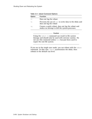
Table 3–2 halt Command Options
Option Function
-l Does not log the halt
-n Prevents the use of sync to write data to the disks and
does not log the halt
-q Causes a quick halt; does not log the halt and makes
no attempt to kill the system processes
System Shutdown and Startup 3–7](https://image.slidesharecdn.com/dunix-141227095156-conversion-gate02/85/Dunix-sys-operating-123-320.jpg)
![Shutting Down and Rebooting the System
For example:
# halt
syncing disks... done
halting.... (transferring to monitor)
The halt is logged in /usr/adm/syslog.dated/date/auth.log.
Using the
fasthalt
Command
The fasthalt command halts the system and flags a subsequent
reboot not to carry out a file system consistency check (fsck).
The fasthalt command:
• Creates the file /fastboot, used by startup scripts to prevent
the execution of fsck
• Invokes the halt command to halt the processors
Note
Use the fasthalt command with extreme caution and
never use it unless you are certain that the file systems
are in excellent shape.
The format for the fasthalt command is:
fasthalt [-l -n -q]
The options for the fasthalt command are described in
Table 3–3.
Table 3–3 fasthalt Command Options
Option Function
-l Does not log the halt
-n Prevents the use of sync to write data to the disks and
does not log the halt
-q Causes a quick halt; does not log the halt and makes
no attempt to kill the system processes
Shutting Down
to Single User
Mode with init
Use the init command to shut down the system from multiuser
mode to single user mode.
The format for the command is:
init s
The init command scans the /etc/inittab file to determine which
commands and scripts must be run to bring the system to single
user mode.
3–8 System Shutdown and Startup](https://image.slidesharecdn.com/dunix-141227095156-conversion-gate02/85/Dunix-sys-operating-124-320.jpg)
![Shutting Down and Rebooting the System
Stopping the
Processor with
init
A Digital UNIX system may be halted with the init command.
The format for the command is:
init 0
The init command scans the /etc/inittab file to determine which
commands and scripts must be run to bring the system to halt
mode.
The init command may be executed in either multiuser or
single user mode. You would not normally use init to shut down
the system or halt the system unless you have provided ample
warning to the users with the wall command.
Other Methods
of Shutting
Down the
System
Other methods for shutting down the system include:
• Sending the TERM signal (15) to the init process brings the
system to single user mode.
• Sending the KILL signal (9) to the init process may bring the
system to console level.
• Turning off the power.
Note
These methods are not recommended for shutting down
a system because the results are unpredictable. The
best way to shut down the system is with the shutdown
command.
Rebooting the
System
If you make changes to system software or configuration files that
are executed only when the system is booted, you must reboot for
these changes to take effect. Also some devices, such as printers,
can become unusable for unknown reasons and require resetting,
which may not be possible without reinitializing the system.
Under these circumstances, you may have to reboot the system.
Using the
reboot
Command
The reboot command normally stops all processes, synchronizes
the disks, logs the reboot, and writes a shutdown entry into the
login accounting file.
The reboot command does not provide a time delay, nor does it
inform users of an impending shutdown and reboot. Do not use
the reboot command if users are logged in; use the shutdown -r
command instead.
You must have root privileges to use the reboot command.
The format for the reboot command is:
reboot [-lnq]
The descriptions of the various reboot options are shown in
Table 3–4.
System Shutdown and Startup 3–9](https://image.slidesharecdn.com/dunix-141227095156-conversion-gate02/85/Dunix-sys-operating-125-320.jpg)
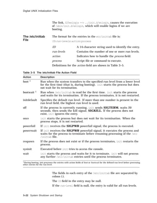
![Digital UNIX Initialization Files
Example 3–4 An /sbin/rc2 File
trap "echo" 2 1
PATH=/sbin:/usr/sbin:/usr/bin
export PATH
# Just exit if /usr not mounted.
if [ ! -d "/usr/sbin" ] 2
then
exit
fi
# Determine action from runlevel information
set ‘who -r‘ 3
if [ $9 = "S" ]; then 4
stty sane tab3 2>/dev/null
echo "The system is coming up. Please wait..."
BOOT=yes
elif [ $7 = "2" ]; then 5
echo "Changing to system level 2."
if [ -d /sbin/rc2.d ]; then
for f in /sbin/rc2.d/K*
do
if [ -s $f ]; then
/sbin/sh $f stop
fi
done
fi
fi
if [ -d /sbin/rc2.d ]; then 6
for f in /sbin/rc2.d/S*
do
if [ -s $f ]; then
/sbin/sh $f start
fi
done
fi
if [ "$BOOT" = "yes" -a $7 = "2" ]; then 7
echo "The system is ready."
elif [ $7 = "2" ]; then 8
echo "Change to state 2 has been completed."
fi
An explanation of the /sbin/rc2 script file follows:
1 The trap prevents an interrupt from killing the script.
2 If the /usr/sbin directory is not mounted, terminate execution
of this script. The /usr/sbin directory contains commands
executed by the script files in /sbin/init.d.
3 Use the who -r command to determine the current system run
level.
4 If the change is from single user mode (parameter 9 is "S") we
must be booting to run level 2 or 3.
Reset the console terminal to a reasonable value and
redirect error output to the bit bucket.
Echo the message that the system is coming up to the
console terminal.
System Shutdown and Startup 3–25](https://image.slidesharecdn.com/dunix-141227095156-conversion-gate02/85/Dunix-sys-operating-141-320.jpg)

![Firmware Systems
>>> command [-flags] [parameters ...]
Examples of console commands are:
>>> sh auto
AUTO_ACTION = HALT
>>> sh bootdef_dev
BOOTDEF_DEV = DKA300
>>> sh boot_osflags
BOOT_OSFLAGS = A
SRM
Commands
and Tasks
System management task support is provided through the
SRM console allowing the operator or user to customize the
environment or take special actions. Table 4-1 briefly lists some
of these tasks with the command used.
Table 4–1 Administrator Tasks
Task Command
Boot the operating system
software
boot
Change the default startup action set auto_action
Initialize the system init
Set the default operating system set os_type
Display the system configuration show config
Invoke the ARC console firmware arc
There are certain system management tasks that can only be
performed using the SRM console.
• The test command to test the system
• The show fru command (field replaceable unit) to examine
system bus options for errors
• To set or change certain environment variables such as enable
multiple CPUs or fast SCSI devices as an example
Note
For a complete SRM console command list with
explanatory information consult your Firmware Reference
Guide for the hardware platform required. For example,
AlphaServer 2000/2100, or DEC3000 M500.
4–6 Updating System Firmware](https://image.slidesharecdn.com/dunix-141227095156-conversion-gate02/85/Dunix-sys-operating-156-320.jpg)
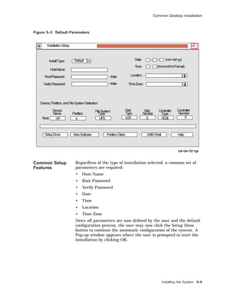
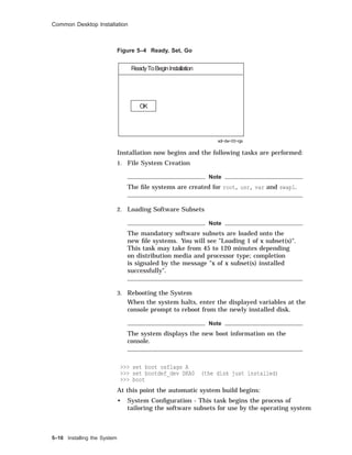
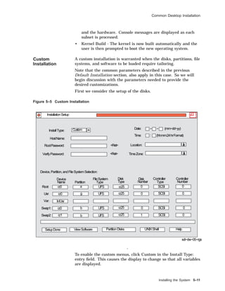
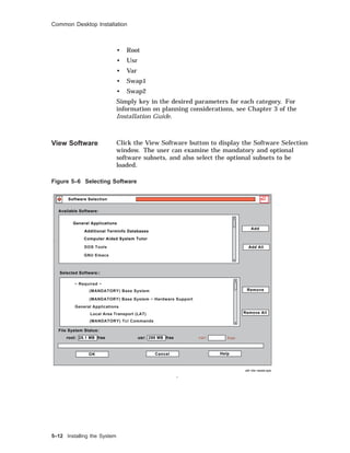
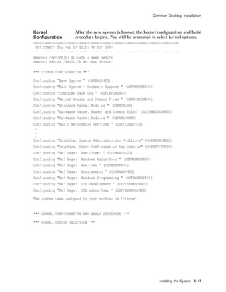
![Common Desktop Installation
Selection Kernel Option
--------------------------------------------------------------
1 System V Devices
2 Logical Volume Manager (LVM)
3 NTP V3 Kernel Phase Lock Loop (NTP_TIME)
4 Kernel Breakpoint Debugger (KDEBUG)
5 Packetfilter driver (PACKETFILTER)
6 Point-to-Point Protocol (PPP)
7 STREAMS pckt module (PCKT)
8 X/Open Transport Interface (XTISO, TIMOD, TIRDWR)
9 File on File File System (FFM)
10 ISO 9660 Compact Disc File System (CDFS)
11 Audit Subsystem
12 ACL Subsystem
13 All of the above
14 None of the above
15 Help
--------------------------------------------------------------
Enter the selection number for each kernel option you want.
For example, 1 3 [14]: 6
You selected the following kernel options:
Point-to-Point Protocol (PPP)
Is that correct? (y/n) [y]: y
Do you want to edit the configuration file? (y/n) [n]:
The system will now automatically build a kernel
and then reboot. This will take approximately 15
minutes, depending on the processor type.
When the login prompt appears after the system
has rebooted, use ’root’ as the login name and
the SUPERUSER password that was entered during
this procedure, to log into the system.
*** PERFORMING KERNEL BUILD ***
Working....Thu Feb 29 13:01:10 EST 1996
Working....Thu Feb 29 13:03:11 EST 1996
Error opening license database /var/adm/lmf/ldb
lmf: No such file or directory
-------------------------------------------------------------------------
%IT STOP% Thu Feb 29 12:55:40 EST 1996
-------------------------------------------------------------------------
Post
Installation
Login and
Setup
When you log in to the system (with graphics capability) for the
first time, the CDE login window is displayed. Enter root as
the username and then enter the root password specified at the
beginning of the installation. The display window created has
four components:
• A Help Viewer window, Introducing the Desktop
• A Pop-up window labeled: Action Required
5–18 Installing the System](https://image.slidesharecdn.com/dunix-141227095156-conversion-gate02/85/Dunix-sys-operating-182-320.jpg)
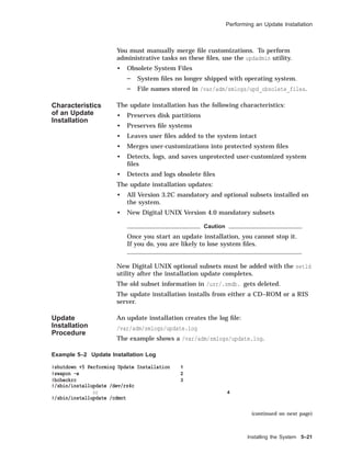
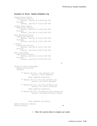
![Performing an Update Installation
Example 5–2 (Cont.) Update Installation Log
Working....Mon Feb 28 15:01:22 EST 1994
The Digital UNIX 4.0 Update Installation will update the
following Digital UNIX products:
Digital UNIX V3.2C
Digital Equipment Corporation recommends that you perform complete
system software backups before proceeding.
Press RETURN to review message again.
Do you want to continue the update installation? (y/n) []:y 5
****** Checking current state of system
Depending on the system configuration, this may take
up to 20 minutes...
Working....Mon Feb 28 15:04:02 EST 1994
Working....Mon Feb 28 15:06:02 EST 1994
Working....Mon Feb 28 15:08:02 EST 1994
Working....Mon Feb 28 15:12:02 EST 1994
Working....Mon Feb 28 15:15:02 EST 1994
Working....Mon Feb 28 15:18:02 EST 1994
Unprotected customized system files have been found on
this system and have been saved to ’filename.PreUPD’.
A listing of the files has been logged in
/var/adm/smlogs/upd_custom_files. 6
After the update installation has completed, use the
Update Administration Utility (/usr/sbin/updadmin)
to perform system administration tasks on these files.
****** Updating system to Digital UNIX V4.0
Working....Mon Feb 28 15:23:02 EST 1994
Base System
Copying from /dev/rz4c
Working....Mon Feb 28 15:26:11 EST 1994
Verifying
Working....Mon Feb 28 15:28:02 EST 1994
Base System - Hardware Support
Copying from /dev/rz4c
Working....Mon Feb 28 15:33:19 EST 1994
Verifying
Working....Mon Feb 28 15:35:02 EST 1994
Compiler Backend
Copying from /dev/rz4c
Working....Mon Feb 28 15:36:19 EST 1994
Verifying
Working....Mon Feb 28 15:37:02 EST 1994
Kernel Header and Common Files
Copying from /dev/rz4c
Working....Mon Feb 28 15:38:19 EST 1994
Verifying
Working....Mon Feb 28 15:38:59 EST 1994
(continued on next page)
5–22 Installing the System](https://image.slidesharecdn.com/dunix-141227095156-conversion-gate02/85/Dunix-sys-operating-186-320.jpg)
![Performing an Update Installation
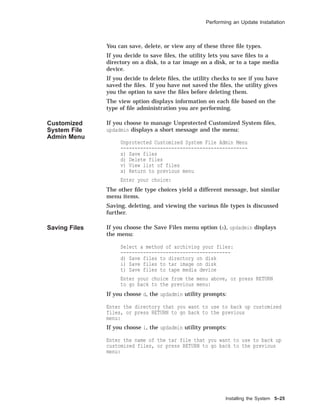
If you choose t, the updadmin utility prompts:
Enter the name of the tape backup device (for example: /dev/nrmt0h)
that you want to use to back up customized files, or press RETURN
to go back to the previous menu:
Deleting Files If you choose d from the File Admin menu to delete files, updadmin
looks to see if the files were backed up. If they were not, it
displays a message similar to:
==================================================================
Back up customized files not detected.
If you have not backed up the customized files yet, please do so at
this time by answering ’no’ to the question below and selecting the
’s’ option from the previous menu:
===================================================================
Please confirm your intent to delete customized system files
from the system. [y/n]:
Viewing Files The view option displays a list of files based on your updadmin
main menu selection. If you choose to display Unprotected
Customized files, updadmin lists files by Digital UNIX subset name
similar to:
============================================
== Unprotected Customized OSFBASE Files
============================================
./usr/sbin/setup.PreUPD (DELETED FROM SYSTEM)
./etc/zoneinfo/Australia/South.PreUPD (DELETED FROM SYSTEM)
=============================================
== Unprotected Customized OSFINET Files
=============================================
./usr/sbin/screend.PreUPD (DELETED FROM SYSTEM)
./usr/named.PreUPD (DELETED FROM SYSTEM)
Enter ’r’ to review files again, or press RETURN to go back
to the previous menu:
5–26 Installing the System](https://image.slidesharecdn.com/dunix-141227095156-conversion-gate02/85/Dunix-sys-operating-190-320.jpg)


![TCP/IP Files
TCP/IP Files
Overview The Internet, or TCP/IP network, is configured using a number of
files, as described in the table.
Table 6–2 TCP/IP Network Files
File Function
/etc/hosts Lists known hosts and their addresses.
/etc/hosts.equiv Lists trusted hosts for login purposes.
(Optional)
/etc/hosts.lpd Lists trusted hosts for remote printer use.
(Optional)
/etc/inetd.conf Lists Internet services managed by the
inetd(8) daemon.
/etc/networks Lists network and subnetwork names.
/etc/protocols Lists known Internet protocols.
/etc/services Lists known Internet services and port
numbers.
There are also a number of daemons used in TCP/IP networking:
inetd Internet service daemon. When it receives a service
request, it invokes a process to service the request.
rwhod Daemon maintains the database used by rwho(1) and
ruptime(1). It periodically queries the state of the
system and broadcasts it to other systems; it receives
status broadcasts and stores status in the /var/rwho
directory.
routed Daemon manages network routing tables.
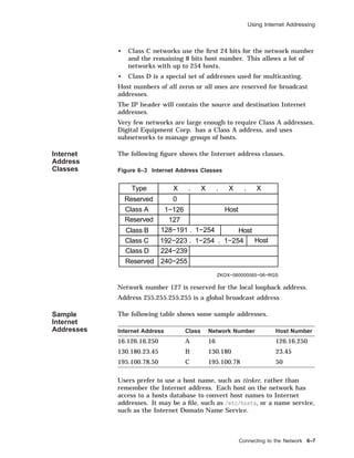
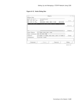
Hosts File The /etc/hosts file contains a list of the known hosts on the
network.
Each host is listed on a separate line with fields separated by
blanks. The format is:
address hostname [alias . . . ]
#
# Host Database
#
127.0.0.1 localhost
128.12.5.2 tinker
128.12.5.1 TAILOR tailor taylor
128.12.5.3 SOLDIER soldier
128.12.7.2 SPY007 spy
6–12 Connecting to the Network](https://image.slidesharecdn.com/dunix-141227095156-conversion-gate02/85/Dunix-sys-operating-206-320.jpg)
![TCP/IP Files
The host file allows the system to look up the Internet address,
given a host name. The system administrator can edit this file
and add or remove entries to add or remove a host system on the
network.
A system on a busy network might have an /etc/hosts file
hundreds of lines long. It is not practical to keep this type of
list up to date. Many systems now use the Internet Domain
Name Service (implemented by BIND), where a name server
dynamically provides the host name to address lookups.
The UNIX term host is equivalent to node in DECnet terminology.
Trusted Hosts
File
The /etc/hosts.equiv file specifies which hosts are trusted on
your system. This is a systemwide file maintained by the root
user.
This file:
• Has impact on only the local host.
• Allows a user from a remote system to:
Log in to the same account on your system without a
password (using rlogin)
Copy a file from your system (using rcp)
Execute a command on your system (using rsh)
Enter one system name and optional user names per line.
# Trusted hosts
tailor joe sam
spy
The ~/.rhosts file allows an individual user to specify which hosts
and accounts are trusted on your system in his account.
This file:
• Can exist in each user’s home directory
• Allows a user from a remote system to:
Log in to the same account on your system without a
password (using rlogin)
Copy a file from your system (using rcp)
Execute a command on your system (using rsh)
The file format is:
hostname [username]
Connecting to the Network 6–13](https://image.slidesharecdn.com/dunix-141227095156-conversion-gate02/85/Dunix-sys-operating-207-320.jpg)
![TCP/IP Files
Networks File The /etc/networks file allows file hosts on the same network or
subnetwork to be referred to as a group.
• Enter each network on a single line with fields separated by
blanks.
• Format is:
netname netnumber [alias . . . ]
The first field is the network name.
The second field is the network number (just the network
part of the Internet address).
Any remaining fields are aliases.
• Example
# Internet networks
#
loop 127 loopback
engineering 128.12.5 eng
accounting 128.12.7 act
Some commands, such as route(8) will accept a network name as
an argument.
The netstat(1) command can display network names defined in
/etc/networks.
The /etc/networks file is installed with the loop network name.
Other entries are optional.
Protocols File The /etc/protocols file lists the known Internet protocols and
their numbers.
• List each protocol on a separate line along with its protocol
number and any aliases.
# Internet (IP) protocols
#
ip 0 IP # internet protocol, pseudo protocol number
icmp 1 ICMP # internet control message protocol
ggp 3 GGP # gateway-gateway protocol
tcp 6 TCP # transmission control protocol
pup 12 PUP # PARC universal packet protocol
udp 17 UDP # user datagram protocol
• Modify this file to add a protocol to the network.
The protocols file is installed properly when set up for standard
protocols.
If a programmer writes his or her own protocol, it should be
added to /etc/protocols for inetd to manage daemons using it.
Connecting to the Network 6–15](https://image.slidesharecdn.com/dunix-141227095156-conversion-gate02/85/Dunix-sys-operating-209-320.jpg)


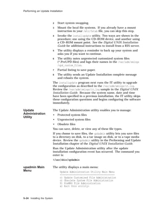
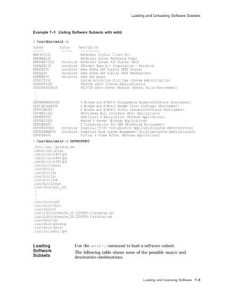
![Loading and Unloading Software Subsets
Loading and Unloading Software Subsets
Preparing to
Load Software
Digital UNIX software is organized into subsets.
Use the setld(8) command to load and manage software subsets
from a distribution media after installation.
Before loading subsets, you may wish to check for sufficient disk
space:
• Use df to determine disk space.
• Consult the Release Notes for subset sizes and file systems
affected.
Note
setld will automatically check that there is adequate file
space for the subset(s) requested to be installed.
Using the setld
Command
The format for the setld command is:
/usr/sbin/setld [-D dir] -option [location]
[subset...]
• dir is an optional path specifying the destination.
• option includes:
l loads subset from distribution on location and updates
the internal inventory.
d deletes subset from the system and updates the internal
inventory.
i gives an inventory of all subsets known to the system, or
all files for subset.
c configures subset by passing a message to the subset
control program.
x extracts subset from distribution on dev into current
working directory or dir (does not update internal
inventory).
v verifies subset by checking its existence and by running
its installation verification procedure.
Except for the -i option, you must be superuser to run
setld.
• location specifies the distribution location. location can be:
A device special file name: /dev/rz4c—CD–ROM
The name of a directory: /mnt/ALPHA — disk distribution
directory
Loading and Licensing Software 7–3](https://image.slidesharecdn.com/dunix-141227095156-conversion-gate02/85/Dunix-sys-operating-225-320.jpg)
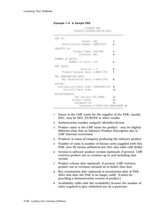
![Licensing Your Software
If any data is incorrect, LMF displays the appropriate
error message and gives you an opportunity to reenter the
data.
Example 7–5 shows how to use the lmfsetup command.
Example 7–5 Using the lmfsetup Command
# lmfsetup
Register PAK (type q or quit to exit) [template] Return
Issuer : DEC
Authorization Number : SQM021856
Product Name : OSF-SVR
Producer : DEC
Number of units : 100
Version : 1.0
Product Release Date : 1-MAR-1996
Key Termination Date : 1-APR-1996
Availability Table Code : CONSTANT=100
Activity Table Code :
Key Options : NO_SHARE
Product Token :
Hardware-Id :
Checksum : 1-POFE-IHOI-FHNH-KHDK
Loading and Licensing Software 7–13](https://image.slidesharecdn.com/dunix-141227095156-conversion-gate02/85/Dunix-sys-operating-235-320.jpg)
![Solutions
Licensing Your
Software
1.
# lmf list
No entries in license database
2.
# lmf register
(displays template using editor)
Licensed Software Product
Product Authorization Key
Enter data on lines terminated with:
Issuer : DEC
Authorization Number : SQM021856
Product Name : OSF-SVR
Producer : DEC
Number of units : 100
Version : 1.0
Product Release Date : 1-MAR-1996
Key Termination Date : 1-APR-1996
Availability Table Code : CONSTANT=100
Activity Table Code :
Key Options : NO_SHARE
Product Token :
Hardware-Id :
Checksum : 1-POFE-IHOI-FHNH-KHDK
Comment:
Checksum does not validate
Abort (a), Retry with new template (n), Retry with old template (o) ? a
#
3.
# lmfsetup
(prompts each line)
Register PAK (type q or quit to exit) [template] Return
Issuer : DEC
Authorization Number : SQM021856
Product Name : OSF-SVR
Producer : DEC
Number of units : 100
Version : 1.0
Product Release Date : 1-MAR-1996
Key Termination Date : 1-APR-1996
Availability Table Code : CONSTANT=100
Activity Table Code :
Key Options : NO_SHARE
Product Token :
Hardware-Id :
Checksum : 1-POFE-IHOI-FHNH-KHDK
Checksum does not validate
Do you wish to retry? [Yes] N
PAK registration for template canceled
Register PAK (type q or quit to exit) [template] q
#
7–24 Loading and Licensing Software](https://image.slidesharecdn.com/dunix-141227095156-conversion-gate02/85/Dunix-sys-operating-246-320.jpg)


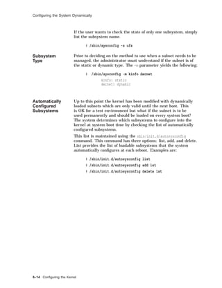
![Building a Static Kernel
Building a Static Kernel
Overview The doconfig program creates a new (or modifies an existing)
system configuration file, creates the special device files for
statically configured drivers, and builds a new Digital UNIX
system kernel.
You need the following Digital UNIX software subsets installed to
rebuild your kernel:
• OSFBINnnn
• OSFBINCOMnnn
nnn corresponds to the operating system version.
Use setld -i to verify that these subsets are installed.
Using the
doconfig
Program
The following example shows how to automatically build a
kernel.
Example 8–2 Building a Kernel with the doconfig Program
1 $ su
2 # cp /vmunix /vmunix.old
3 # cp /genvmunix /vmunix
4 # /usr/sbin/shutdown -r now Boot generic kernel
5 # /usr/sbin/shutdown now To single-user mode
6 # /usr/sbin/doconfig
*** KERNEL CONFIGURATION AND BUILD PROCEDURE ***
*** FILE NAME SPECIFICATION ***
Enter a name for the kernel configuration file. [TINKER] Return
A configuration file with the name ’TINKER’ already exists.
Do you want to replace it? (y/n) [n]: y
. . .
*** KERNEL OPTION SELECTION ***
Selection Kernel Option
---------------------------------------------------------------
1 Streams Socket Coexistence (DLPI & STRIFNET)
2 Data Link Interface (DLI)
3 X/Open Transport Interface (XTISO)
4 ISO 9660 Compact Disc File System (CDFS)
5 All of the above
6 None of the above
---------------------------------------------------------------
Enter the selection number for each kernel option you want.
For example, 1 3 : 4
. . .
(continued on next page)
8–10 Configuring the Kernel](https://image.slidesharecdn.com/dunix-141227095156-conversion-gate02/85/Dunix-sys-operating-258-320.jpg)
![Building a Static Kernel
Example 8–2 (Cont.) Building a Kernel with the doconfig Program
Configuration file complete.
Do you want to edit the configuration file? (y/n) [n]: Return
*** CREATING SPECIAL FILES FOR DEVICES ***
A log file listing special device files is located in /dev/MAKEDEV.log
*** PERFORMING KERNEL BUILD ***
. . .
The new kernel is /sys/TINKER/vmunix.
7 # mv /sys/TINKER/vmunix /vmunix
8 # /usr/sbin/shutdown -r now Boot new kernel
1 You must be the root user to run doconfig and shut down the
system.
2 Optionally, save a copy of the running kernel. If there is not
sufficient space in the root file system, save it elsewhere.
3 When creating a new configuration file or adding new
hardware with doconfig, the system must be running the
generic kernel so that it can recognize all devices.
4 Reboot the system using the generic kernel.
5 Log in as root and shut down the system to single-user mode.
6 Run the doconfig program.
• The script will ask questions about the configuration file
(system) name and time zone and give you the option to
edit the configuration file. (The prompts will be familiar to
anyone who has run the installation script.)
• doconfig builds a new kernel and displays its pathname.
7 Move the new kernel to the root directory.
8 Reboot the system.
Note
If there are problems booting the new kernel, there may
be errors in the configuration file. You can boot the generic
kernel to single-user mode and copy the original kernel
back to /vmunix.
You can build a new kernel from an existing configuration
file by using doconfig with the -c option and the name of the
configuration file to bypass the questions, for example:
doconfig -c TINKER
You do not need to be running the generic kernel, and you need
to reboot only once after moving the new kernel to /vmunix. You
should still save the original kernel before creating a new one.
Configuring the Kernel 8–11](https://image.slidesharecdn.com/dunix-141227095156-conversion-gate02/85/Dunix-sys-operating-259-320.jpg)


![Adding Terminals on a Terminal Server
Example 9–2 (Cont.) Using the latsetup Utility
Exit
Initial LAT Setup
Create Additional Devices
Start/Stop LAT
Enable/Disable
LAT Automatic Startup/Shutdown
Undo LAT Setup
To select an option, use the <UP> or <DOWN> arrow keys and press <RETURN>
to enter the chosen submenu. To select options on a horizontal plane use the
<LEFT> or <RIGHT> arrow keys and press <RETURN>. To enter input,
type it in and then press <RETURN>.
Initial LAT Setup
This menu will allow you to setup LAT on your system by creating LAT
special device files, selecting how many getty entries should be placed
into /etc/inittab and choosing whether or not to execute init q. LAT will
be started to allow interactive connections to be made to this system and
a variable will be set in /etc/rc.config so that LAT automatic startup
and shutdown is enabled which will cause LAT to be started each time
this system reaches run-level 3.
Would you like to continue with this option?
YES NO
There are 16 LAT tty devices created.
There are 8 LAT entries already defined in /etc/inittab.
Select style of ttuys to create
SVR4 style ttys
BSD style ttys
How many LAT ttys do you want to create? (0 - 617) [0] 1
How many gettys would you like added to the /etc/inittab file? (0 - 1) [0] 1
NOTE: Please keep your system’s memory resources
in mind when specifying gettys to be added.
Would you like init q to be executed to spawn the new getty entries in
the /etc/inittab file?
YES NO
You requested: 1 tty and 1 getty and that init q be performed.
Are you satisfied with this input?
YES NO
Working on your request.
LAT tty devices have been created and getty entries defined.
There are now 1 LAT tty devices created.
There are now 1 LAT entries defined in /etc/inittab.
Enter <RETURN> to return to main menu
Return
LAT Setup Utility
(continued on next page)
Configuring Peripherals 9–11](https://image.slidesharecdn.com/dunix-141227095156-conversion-gate02/85/Dunix-sys-operating-281-320.jpg)
![Adding Terminals on a Terminal Server
Example 9–2 (Cont.) Using the latsetup Utility
The latsetup program provides assistance in setting up LAT on your system.
If this is the first time running latsetup on this system, it is recommended
to select the Initial LAT Setup option.
Exit
Initial LAT Setup
Create Additional Devices
Start/Stop LAT
Enable/Disable
LAT Automatic Startup/Shutdown
Undo LAT Setup
#
Controlling the
LAT Service
The latcp command controls and manages the LAT terminal
service. It allows you to start and stop LAT service and modify
and display configuration characteristics. Some latcp options:
-d Displays LAT host name and status information
-s Starts LAT service; enables connections from LAT
terminal servers to host
-h Halts LAT service
-g group,... Adds group codes to the groups enabled for your
host
-P tty,... Sets a list of ttys as being available only for
host-initiated connections
For example, to set up a host-initiated connection for a printer
connected to a terminal server port:
latcp -A -P tty -H node -R port [-Q]
• tty is the tty device to associate with the printer
• node is the name of the terminal server where the printer is
connected
• port is the name of the port on the terminal server
• -Q does not queue requests if the port is busy
The latcp command on Digital UNIX is similar to lcp on ULTRIX.
An alternative to the example is to specify the node and port in
the /etc/printcap file. Do not specify them in both places.
9–12 Configuring Peripherals](https://image.slidesharecdn.com/dunix-141227095156-conversion-gate02/85/Dunix-sys-operating-282-320.jpg)
![Managing the Print System
This lpd exists as long as there are files in this queue.
Print System
Control
Commands
The following table lists the main commands to control the print
system.
Table 9–1 Print System Commands
Command Function
lp(1) Creates a print request
lpr(1) Creates a print request
lpq(1) Displays a printer queue
lprm(1) Removes print requests from a queue
lpstat(1) Displays printer status
lpc(8) Enables or disables a printer or printer queue;
rearranges the order of jobs in a queue; checks the
status of a printer, a queue and the printer daemon
lptest(8) Generates a test pattern
CDE Print
Manager
Displays print job status, finds a print job (among
known printers), and allows user to select printers
to be displayed in the Print Manager window
See the Reference Pages for more information.
Note
PrintServer printers require special software.
Using
the lptest
Command
The lptest(8) command generates a ripple test pattern of
printable ASCII characters to standard output. It can be used by
anyone to test terminals and printers.
The format for the lptest command is:
lptest [length [count]]
• length specifies the length of the output line; default is 79
characters.
• count specifies the number of output lines; default is 200 lines.
When count is specified, length must also be specified.
To send the test pattern to a printer, you can redirect standard
output
# lptest > /dev/tty02
# lptest | lpr - -P2
The following is an example of the lptest command.
9–22 Configuring Peripherals](https://image.slidesharecdn.com/dunix-141227095156-conversion-gate02/85/Dunix-sys-operating-292-320.jpg)
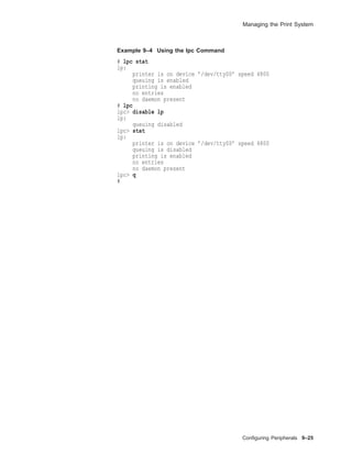
![Managing the Print System
Table 9–2 Line Printer Control Commands
lpc Command Function
abort {all | printer} Terminates an active spooling daemon on the local host,
then disables printing (preventing new daemons from
starting). This is usually used with start to restart a
hung printer daemon (that is, lpq reports daemon present,
but nothing is printing).
disable {all | printer} Turns off the queue(s). (Sets group execute permission on
the lock file.)
enable {all | printer} Allows spooling on the queue(s). (Removes group execute
permission on the lock file.)
stop {all | printer} Stops the daemon after the current job completes and
disables printing. (Sets owner execute permission on the
lock file.)
start {all | printer} Enables printing and starts a daemon for the printer(s).
(Removes owner execute permission on the lock file.)
restart {all | printer} Attempts to start a new daemon. This is useful when the
daemon fails unexpectedly, leaving jobs in the queue (and
lpq reports "No daemon present").
status [printer] Displays the status of daemons and queues.
up [all | printer] Enables queuing and printing and starts a new daemon.
topq printer [job] [user] Moves jobs to the top of the printer queue.
You need queuing enabled and printing enabled in order to print.
The following example shows some typical lpc commands and the
resulting lpc response.
9–24 Configuring Peripherals](https://image.slidesharecdn.com/dunix-141227095156-conversion-gate02/85/Dunix-sys-operating-294-320.jpg)
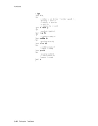
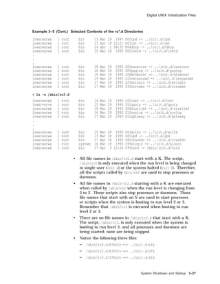
![Solutions
Adding
Terminals on
a Terminal
Server
1.
# grep LAT /sys/conf/TINKER
options LAT
2. See the example in the text.
Dynamic
Device
Recognition
1. # more /etc/ddr.dbase
2. # grep drive /sys/conf/yourhostname
Adding a
Printer with
CDE Printer
Configuration
1. Similar to the "remote" example in the text.
2. See the local printer example in the text.
Managing the
Print System
1. Use lptest
a.
# lptest
!"#$%&’()*+,-./0123456789:;<=>?@ABCDEFGHIJKLMNOPQRSTUVWXYZ[]^_‘abcdefghijklmno
"#$%&’()*+,-./0123456789:;<=>?@ABCDEFGHIJKLMNOPQRSTUVWXYZ[]^_‘abcdefghijklmnop
#$%&’()*+,-./0123456789:;<=>?@ABCDEFGHIJKLMNOPQRSTUVWXYZ[]^_‘abcdefghijklmnopq
$%&’()*+,-./0123456789:;<=>?@ABCDEFGHIJKLMNOPQRSTUVWXYZ[]^_‘abcdefghijklmnopqr
%&’()*+,-./0123456789:;<=>?@ABCDEFGHIJKLMNOPQRSTUVWXYZ[]^_‘abcdefghijklmnopqrs
&’()*+,-./0123456789:;<=>?@ABCDEFGHIJKLMNOPQRSTUVWXYZ[]^_‘abcdefghijklmnopqrst
’()*+,-./0123456789:;<=>?@ABCDEFGHIJKLMNOPQRSTUVWXYZ[]^_‘abcdefghijklmnopqrstu
()*+,-./0123456789:;<=>?@ABCDEFGHIJKLMNOPQRSTUVWXYZ[]^_‘abcdefghijklmnopqrstuv
)*+,-./0123456789:;<=>?@ABCDEFGHIJKLMNOPQRSTUVWXYZ[]^_‘abcdefghijklmnopqrstuvw
.
.
.
b.
# lptest 65 25
c.
# lptest 79 10
d.
# lptest 79 10 >/dev/lp0
2. Use lpc
Configuring Peripherals 9–31](https://image.slidesharecdn.com/dunix-141227095156-conversion-gate02/85/Dunix-sys-operating-301-320.jpg)