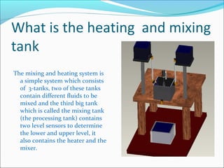
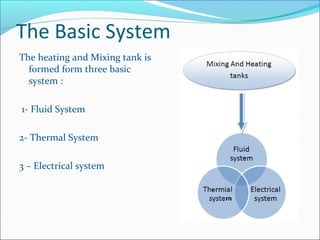
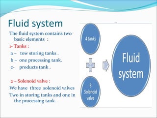
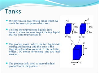
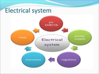
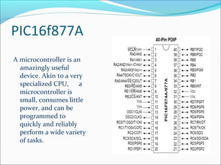
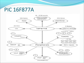
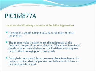
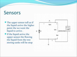
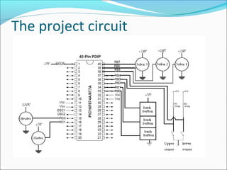
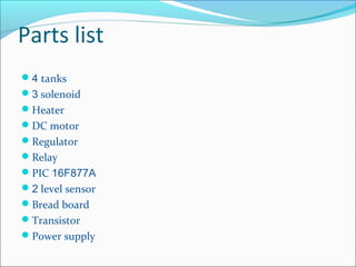
Faculty of Engineering
Mechatronics Department
Design Of Mechatronics Project
Supervisor : Dr. Khalid AL-Wedyan
2007 -2008
Team WorkTeam Work
What is the heating and mixing
tank
The mixing and heating system is
a simple system which consists
of 3-tanks, two of these tanks
contain different fluids to be
mixed and the third big tank
which is called the mixing tank
(the processing tank) contains
two level sensors to determine
the lower and upper level, it
also contains the heater and the
mixer.
The Basic System
The heating and Mixing tank is
formed form three basic
system :
1- Fluid System
2- Thermal System
3 – Electrical system
Fluid system
The fluid system contains two
basic elements :
1- Tanks :
a – tow storing tanks .
b – one processing tank.
c- products tank .
2 – Solenoid valve :
We have three solenoid valves
Two in storing tanks and one in
the processing tank.
Tanks
 We have in our project four tanks which we
use it for many purposes which are :
 To store the unprocessed liquids (two
tanks ) , where we want to put the tow liquid
that we want to processed it.
 The process room , where the two liquids will
mixing and heating and this tank is the
biggest tank and we connect to this tank the
heater , DC motor for mixing , and two level
sensors .
 The product tank used to store the final
product form the process
Solenoids valve
What means of the solenoids valve ?
The solenoids valve is a kind of valve but its
activated by electrical signal
How we connect the solenoid valve ?
We connect it normally closed and when the
signal games to it he will change its state to be
open so the liquid will flow through it until the
signal its stop .
Thermal system
In our project the heater is
the thermal system and
the heat will flow from
the heater to the mixture
liquid .
The maximum temperature
that the heater achieve is
35 C
The heater works when a high
signal actuates the relay this
will close the circuit of the
heater and allow the current
to flow .
Electrical system
PIC16f877A
A microcontroller is an
amazingly useful
device. Akin to a very
specialized CPU, a
microcontroller is
small, consumes little
power, and can be
programmed to
quickly and reliably
perform a wide variety
of tasks.
PIC 16F877A
PIC16f877A
we chose the PIC16F877A because of the following reasons:
It comes in a 40 pin DIP pin out and it has many internal
peripherals.
The 40 pins make it easier to use the peripherals as the
functions are spread out over the pins. This makes it easier to
decide what external devices to attach without worrying too
much if there enough pins to do the job.
Each pin is only shared between two or three functions so it's
easier to decide what the pin function (other devices have up
to 5 functions for a pin).
Regulator
A linear voltage regulated power supply requires an unregulated
voltage that’s higher than the desired regulated voltage. For
example, a 12 V power supply can supply power to a linear
voltage regulator that outputs 5 V.
Linear voltage regulators are popular for the following uses:
Quick, small, simple circuits.
Low cost, high volume products, such as inexpensive
consumer electronics.
Circuits that consumes small amounts (100 mA or less) of
current.
Regulated voltage that just slightly less than the unregulated
voltage.
Relay
When the signal receive from the pic the relay will change from
it state this mean change from normally open to normally
closed and the normally closed to normally open .
And in our project we connect it as normally open with the
directional valve so when the signal came from the pic the
relay became to normally closed so the signal reached the
directional solenoid valve so the valve change it state to be
open
The Mixer
We use a DC motor as mixer
 the speed of the DC motor
is decrease as the torque
increase and so when we but
in the liquid its speed will
decrease.
Its take when it loaded
maximum voltage 24V and
maximum current 5A
Sensors
We use in our project a tow
level sensor to indicate the
level of the liquid .
 We put the tow sensor in
the processing tank one it
the bottom of the tank and
the other one in the upper of
the tank .
The sensor in the bottom of
the tank tell us if the tank is
fully empty or not .
Sensors
The upper sensor tell us if
the liquid arrive the higher
point the we want the
liquid to arrive .
If the liquid arrive the
upper sensor the flowing
the liquid from the tow
storing tanks will be stop
The project circuit
Parts list
4 tanks
3 solenoid
Heater
DC motor
Regulator
Relay
PIC 16F877A
2 level sensor
Bread board
Transistor
Power supply
Question ????????
THE END

Mixing and heating tank

  • 1.
    Faculty of Engineering MechatronicsDepartment Design Of Mechatronics Project Supervisor : Dr. Khalid AL-Wedyan 2007 -2008
  • 2.
  • 3.
    What is theheating and mixing tank The mixing and heating system is a simple system which consists of 3-tanks, two of these tanks contain different fluids to be mixed and the third big tank which is called the mixing tank (the processing tank) contains two level sensors to determine the lower and upper level, it also contains the heater and the mixer.
  • 4.
    The Basic System Theheating and Mixing tank is formed form three basic system : 1- Fluid System 2- Thermal System 3 – Electrical system
  • 5.
    Fluid system The fluidsystem contains two basic elements : 1- Tanks : a – tow storing tanks . b – one processing tank. c- products tank . 2 – Solenoid valve : We have three solenoid valves Two in storing tanks and one in the processing tank.
  • 6.
    Tanks  We havein our project four tanks which we use it for many purposes which are :  To store the unprocessed liquids (two tanks ) , where we want to put the tow liquid that we want to processed it.  The process room , where the two liquids will mixing and heating and this tank is the biggest tank and we connect to this tank the heater , DC motor for mixing , and two level sensors .  The product tank used to store the final product form the process
  • 7.
    Solenoids valve What meansof the solenoids valve ? The solenoids valve is a kind of valve but its activated by electrical signal How we connect the solenoid valve ? We connect it normally closed and when the signal games to it he will change its state to be open so the liquid will flow through it until the signal its stop .
  • 8.
    Thermal system In ourproject the heater is the thermal system and the heat will flow from the heater to the mixture liquid . The maximum temperature that the heater achieve is 35 C
  • 9.
    The heater workswhen a high signal actuates the relay this will close the circuit of the heater and allow the current to flow .
  • 10.
  • 11.
    PIC16f877A A microcontroller isan amazingly useful device. Akin to a very specialized CPU, a microcontroller is small, consumes little power, and can be programmed to quickly and reliably perform a wide variety of tasks.
  • 12.
  • 13.
    PIC16f877A we chose thePIC16F877A because of the following reasons: It comes in a 40 pin DIP pin out and it has many internal peripherals. The 40 pins make it easier to use the peripherals as the functions are spread out over the pins. This makes it easier to decide what external devices to attach without worrying too much if there enough pins to do the job. Each pin is only shared between two or three functions so it's easier to decide what the pin function (other devices have up to 5 functions for a pin).
  • 14.
    Regulator A linear voltageregulated power supply requires an unregulated voltage that’s higher than the desired regulated voltage. For example, a 12 V power supply can supply power to a linear voltage regulator that outputs 5 V. Linear voltage regulators are popular for the following uses: Quick, small, simple circuits. Low cost, high volume products, such as inexpensive consumer electronics. Circuits that consumes small amounts (100 mA or less) of current. Regulated voltage that just slightly less than the unregulated voltage.
  • 15.
    Relay When the signalreceive from the pic the relay will change from it state this mean change from normally open to normally closed and the normally closed to normally open . And in our project we connect it as normally open with the directional valve so when the signal came from the pic the relay became to normally closed so the signal reached the directional solenoid valve so the valve change it state to be open
  • 16.
    The Mixer We usea DC motor as mixer  the speed of the DC motor is decrease as the torque increase and so when we but in the liquid its speed will decrease. Its take when it loaded maximum voltage 24V and maximum current 5A
  • 17.
    Sensors We use inour project a tow level sensor to indicate the level of the liquid .  We put the tow sensor in the processing tank one it the bottom of the tank and the other one in the upper of the tank . The sensor in the bottom of the tank tell us if the tank is fully empty or not .
  • 18.
    Sensors The upper sensortell us if the liquid arrive the higher point the we want the liquid to arrive . If the liquid arrive the upper sensor the flowing the liquid from the tow storing tanks will be stop
  • 19.
  • 20.
    Parts list 4 tanks 3solenoid Heater DC motor Regulator Relay PIC 16F877A 2 level sensor Bread board Transistor Power supply
  • 21.
  • 22.