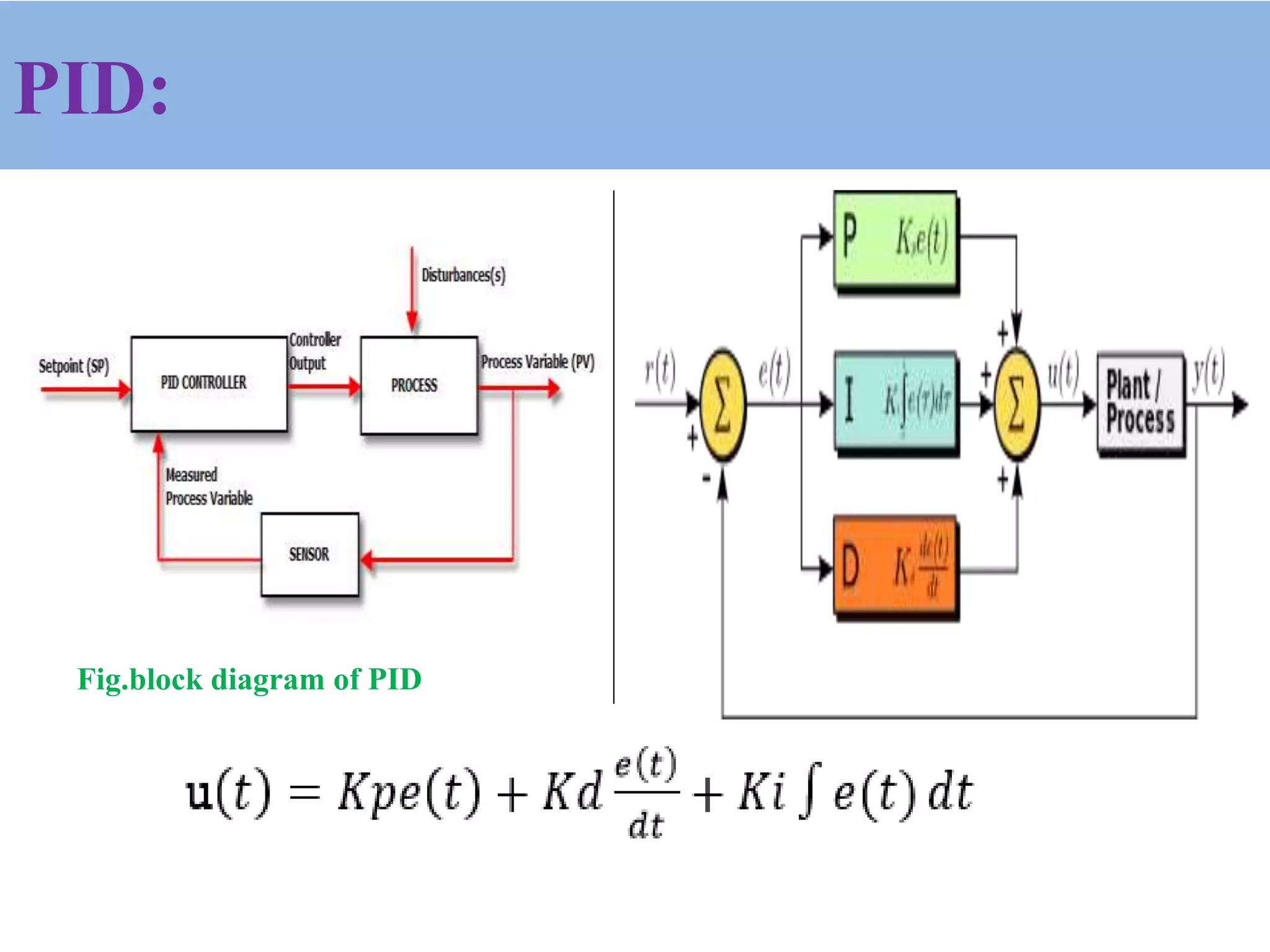
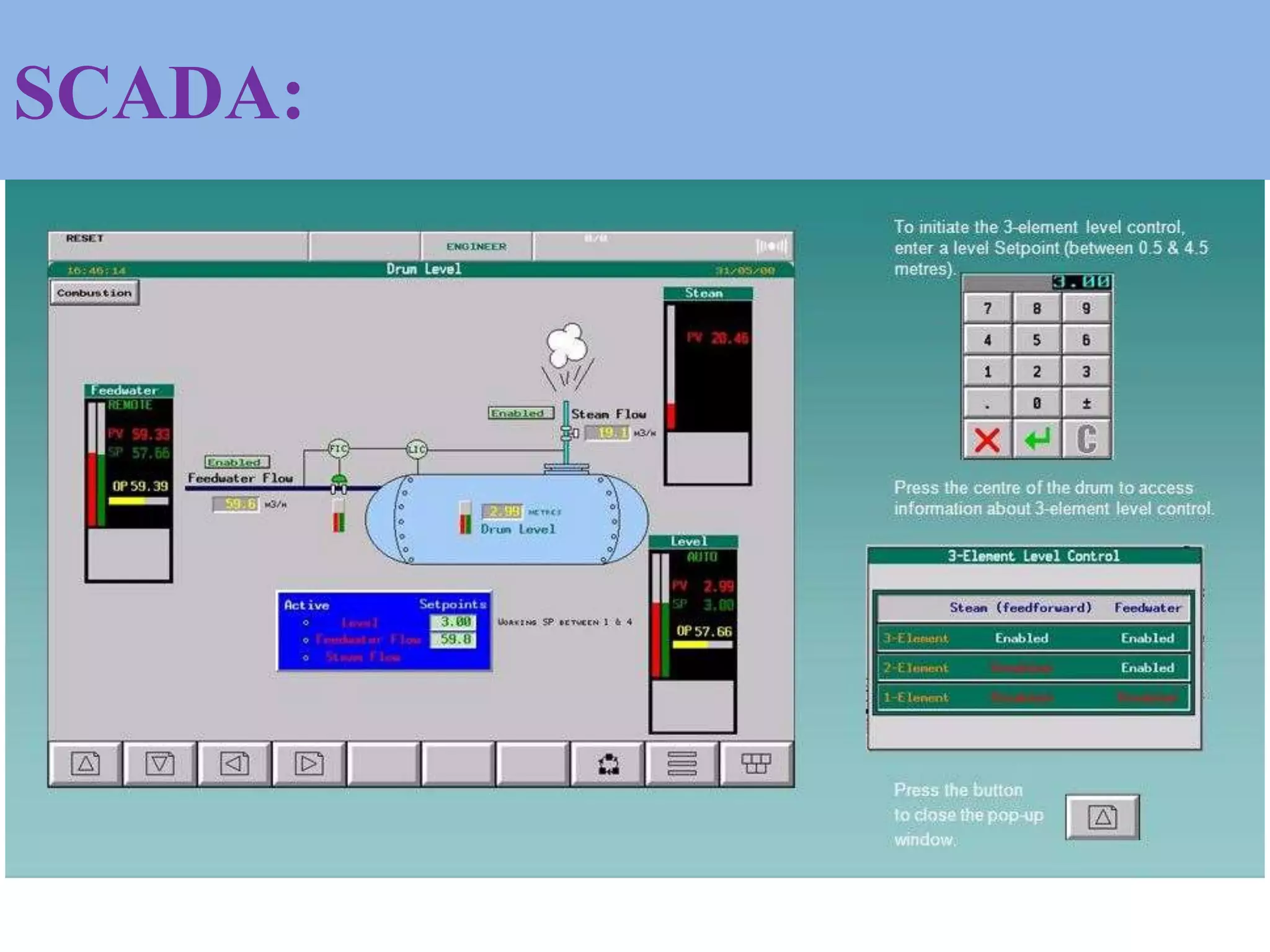
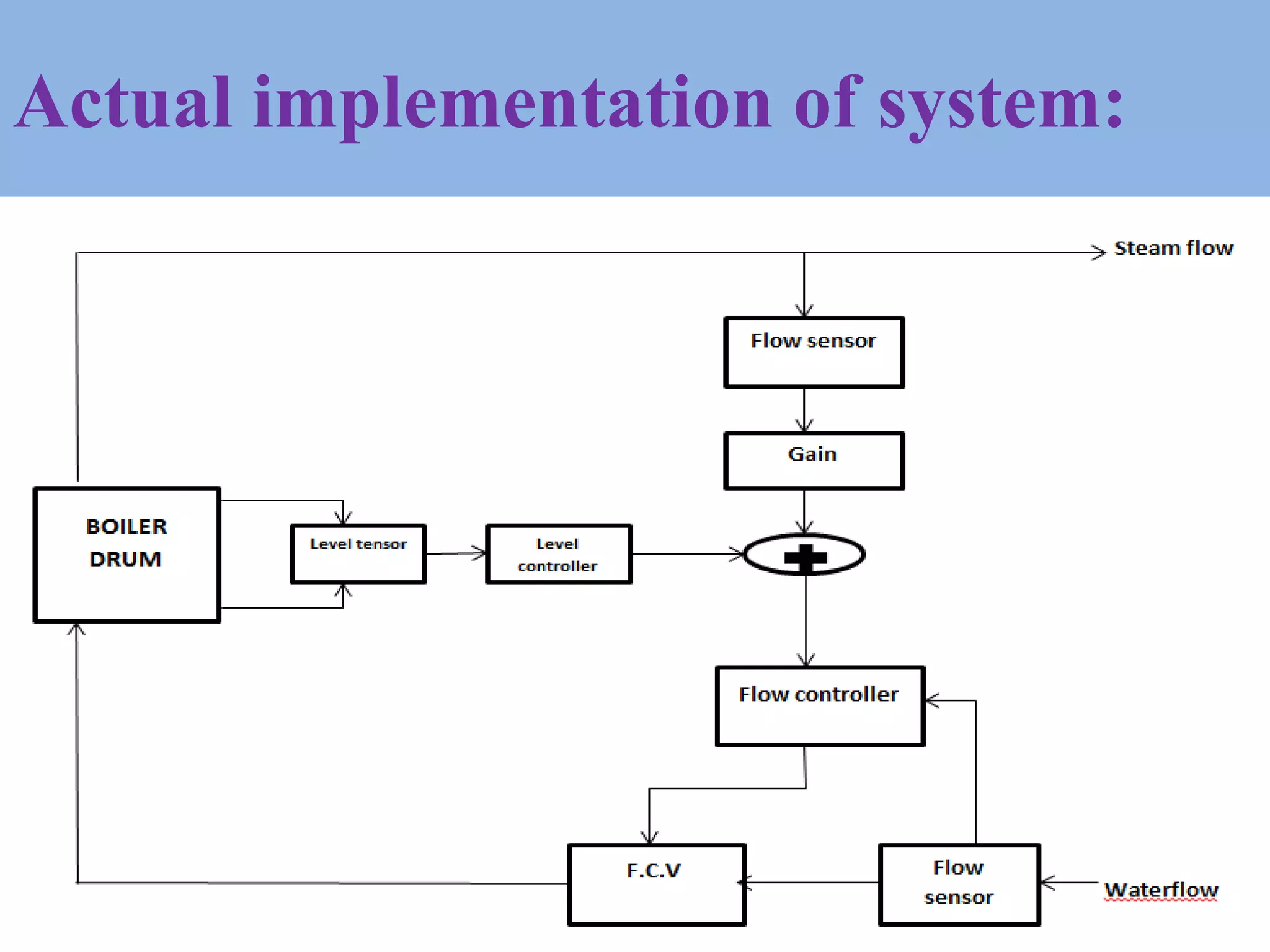
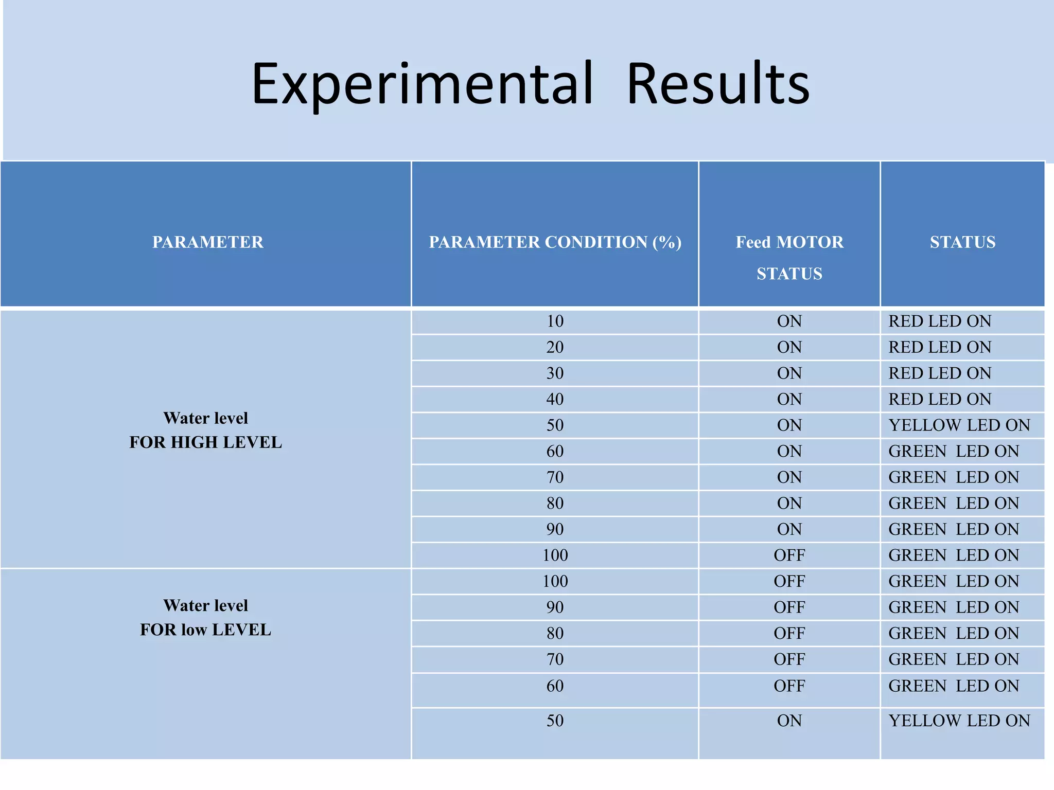
Presented By,
Mr.Godase V. V. [M.E .II.]
(DEPARTMENT OF ELECTRONICS ENGINEERING)
Under the guidance of,
Mr.Jagadale A.B
3 ELEMENT CONTROL USING PLC-
PID & SCADA INTERFACE
Introduction
Limitation of Previous system
Three element control:
Problem Statement:
Aim and Objective:
Configuration of Proposed system
PLC
PID
SCADA
Result
Conclusion
References
CONTENTS:
INTRODUCTION:
Limitation of Previous system &
Need of Automation:
DRUM LEVEL CONTROL:
1]SINGLE ELEMENT CONTROL
2]TWO ELEMENT CONTROL
3]THREE ELEMENT CONTROL
THREE ELEMENT CONTROL:
:
Fig.1.Three element control.
PROBLEM STATEMENT:
AIM & OBJECTIVES:
Major Components of a Common PLC:
INPUT
MODULES PROCESSOR
OUTPUT
MODULES
POWER
SUPPLY
PROGRAMMING
DEVICE
FROM
SENSOR
TO
OUTPUT
Configuration of the Proposed system:
PLC(Programmable Logic Control)
MODEL:
TYPE:
NO OF INPUT:
NO OF OUTPUTS:
AI/AO:
DI/DO:
SUPPLY:
COMMUNICATION :
ADVANTAGES:
Input Modules of PLC’S:
1. Analog input module :
Ex :
2.Digital input module :
Ex :
Output modules
1. Analog Output module :
Ex :
2.Digital Output module :
Ex :
Float Sensor:
• Normally Open Type (NO Type)
• Cable Length:
• Ideal Operating Voltage:
• DC Current:
• Max Switch Current:
• Max Switch Watt:
Fig.Float Sensor:
Pressure Sensor:
• RT type
• Working Voltage:
• Material: Metal
• Output Voltage:
• Working Current:
• Working Pressure Range:
• Features
• Simple design
• High accuracy
• High repeatability
• Long operation life time
Fig.Pressure Sensor
PID:
Fig.block diagram of PID
PID WORKFLOW:
Working:
Fig4.PID Tuning Fig.5.PID Tuning graph
SCADA:
Fig6. schematic representation of SCADA
Actual implementation of system:
Experimental Results
PARAMETER PARAMETER CONDITION (%) Feed MOTOR
STATUS
STATUS
Water level
FOR HIGH LEVEL
10 ON RED LED ON
20 ON RED LED ON
30 ON RED LED ON
40 ON RED LED ON
50 ON YELLOW LED ON
60 ON GREEN LED ON
70 ON GREEN LED ON
80 ON GREEN LED ON
90 ON GREEN LED ON
100 OFF GREEN LED ON
Water level
FOR low LEVEL
100 OFF GREEN LED ON
90 OFF GREEN LED ON
80 OFF GREEN LED ON
70 OFF GREEN LED ON
60 OFF GREEN LED ON
50 ON YELLOW LED ON
BAR
High Pressure
3.5 OFF GREEN LED ON
3.0 OFF GREEN LED ON
2.5 OFF GREEN LED ON
2.0 OFF GREEN LED ON
1.5 ON RED LED ON
1.0 ON RED LED ON
Low Pressure
1.0 ON RED LED ON
1.5 ON RED LED ON
2.0 ON GREEN LED ON
2.5 ON GREEN LED ON
3.0 ON GREEN LED ON
3.5 ON GREEN LED ON
CONCLUSION:
With the help of PLC it can be possible to overcome
drawbacks in drum level of boiler. Thus, we can securely protect
the boiler from blast. In this work, three element control using
PLC-PID and SCADA was designed and controlled. Different
sensors are used to measure the temperature, pressure and water
level. Water level can be measured with level sensors. SCADA
will be used to monitor the parameters and PLC to control the
whole operation. Delta PLC software can used to simulate the
PID & DIAVIEW software for design of drum automation
simulation.
REFERANCES:
• 1] Roopal Agrawal, Umesh C. Pati, ―Design and Data Logging of Three Element Boiler Level Control
Using LabVIEW‖, National Conference on Recent Advances in Chemical and Environmental
Engineering (RACEE), Rourkela, Jan 2018
• [2]Electricaltechnologywebsiteavailablehttps://www.electricaltechnology.org2015/09/what-is-industrial-
automation.html
• [3] S.Kalaivani and M.Jagadeeswari PLC & SCADA Based Effective Boiler Automation System for
Thermal Power Plant International Journal of Advanced Research in Computer Engineering &
Technology (IJARCET) Volume 4 Issue 4, April 2015
• [4] Patel Pratikbhai, 2Rokade Shashikant, 3 Gilbile Sameer, 4S.S.Shingare Design and development of 3
element control of boiler Vol-2 Issue-3 2016
• [5] 1Keyur Solanki, 2Jalpa Shah, 3Nishith Bhatt –‘Modeling and Simulation of prototype of boiler drum
level control’ ISSN (Print) : 2321-5747, Volume-2, Issue-2,2014
• [6] Lakshmi P M1, Dr.H.Prasanna Kumar2’’ One/Three Element Method using PLC DCS” International
Journal of Advanced Research in Electrical, Electronics and Instrumentation Engineering Vol. 5, Issue 8,
August 2016
• [7]1Mr. J.Gnana Arun Johnson, 2Neethu P S, ‘FUZZY LOGIC BOILER DRUM LEVEL CONTROL’
International Journal of Pure and Applied Mathematics Volume 116 No. 23 2017, 463-469
• [8] V. Pavithra, Dr. G. Mary Jansi Rani ‘Boiler Drum Level Control Using Internal Model Controller’©
2015 IJIRT | Volume 1 Issue 12 | ISSN: 2349-6002
• [9] Sayyad Rifat Arbaaz 1, Prof. W.V.Patil2 & Mr. Sunil Panchal3“Development of Advanced Boiler
Automation for Sugar Industries” Imperial Journal of Interdisciplinary Research (IJIR) Vol-3,Issue 2017
Thank You
&
your suggestions
are valued

M.e paper.ppt new (1)

  • 1.
    Presented By, Mr.Godase V.V. [M.E .II.] (DEPARTMENT OF ELECTRONICS ENGINEERING) Under the guidance of, Mr.Jagadale A.B 3 ELEMENT CONTROL USING PLC- PID & SCADA INTERFACE
  • 2.
    Introduction Limitation of Previoussystem Three element control: Problem Statement: Aim and Objective: Configuration of Proposed system PLC PID SCADA Result Conclusion References CONTENTS:
  • 3.
  • 4.
    Limitation of Previoussystem & Need of Automation:
  • 5.
    DRUM LEVEL CONTROL: 1]SINGLEELEMENT CONTROL 2]TWO ELEMENT CONTROL 3]THREE ELEMENT CONTROL
  • 6.
  • 7.
  • 8.
  • 9.
    Major Components ofa Common PLC: INPUT MODULES PROCESSOR OUTPUT MODULES POWER SUPPLY PROGRAMMING DEVICE FROM SENSOR TO OUTPUT
  • 10.
    Configuration of theProposed system:
  • 11.
    PLC(Programmable Logic Control) MODEL: TYPE: NOOF INPUT: NO OF OUTPUTS: AI/AO: DI/DO: SUPPLY: COMMUNICATION : ADVANTAGES:
  • 12.
    Input Modules ofPLC’S: 1. Analog input module : Ex : 2.Digital input module : Ex :
  • 13.
    Output modules 1. AnalogOutput module : Ex : 2.Digital Output module : Ex :
  • 14.
    Float Sensor: • NormallyOpen Type (NO Type) • Cable Length: • Ideal Operating Voltage: • DC Current: • Max Switch Current: • Max Switch Watt: Fig.Float Sensor:
  • 15.
    Pressure Sensor: • RTtype • Working Voltage: • Material: Metal • Output Voltage: • Working Current: • Working Pressure Range: • Features • Simple design • High accuracy • High repeatability • Long operation life time Fig.Pressure Sensor
  • 16.
  • 17.
  • 18.
  • 19.
  • 20.
    Experimental Results PARAMETER PARAMETERCONDITION (%) Feed MOTOR STATUS STATUS Water level FOR HIGH LEVEL 10 ON RED LED ON 20 ON RED LED ON 30 ON RED LED ON 40 ON RED LED ON 50 ON YELLOW LED ON 60 ON GREEN LED ON 70 ON GREEN LED ON 80 ON GREEN LED ON 90 ON GREEN LED ON 100 OFF GREEN LED ON Water level FOR low LEVEL 100 OFF GREEN LED ON 90 OFF GREEN LED ON 80 OFF GREEN LED ON 70 OFF GREEN LED ON 60 OFF GREEN LED ON 50 ON YELLOW LED ON
  • 21.
    BAR High Pressure 3.5 OFFGREEN LED ON 3.0 OFF GREEN LED ON 2.5 OFF GREEN LED ON 2.0 OFF GREEN LED ON 1.5 ON RED LED ON 1.0 ON RED LED ON Low Pressure 1.0 ON RED LED ON 1.5 ON RED LED ON 2.0 ON GREEN LED ON 2.5 ON GREEN LED ON 3.0 ON GREEN LED ON 3.5 ON GREEN LED ON
  • 23.
    CONCLUSION: With the helpof PLC it can be possible to overcome drawbacks in drum level of boiler. Thus, we can securely protect the boiler from blast. In this work, three element control using PLC-PID and SCADA was designed and controlled. Different sensors are used to measure the temperature, pressure and water level. Water level can be measured with level sensors. SCADA will be used to monitor the parameters and PLC to control the whole operation. Delta PLC software can used to simulate the PID & DIAVIEW software for design of drum automation simulation.
  • 24.
    REFERANCES: • 1] RoopalAgrawal, Umesh C. Pati, ―Design and Data Logging of Three Element Boiler Level Control Using LabVIEW‖, National Conference on Recent Advances in Chemical and Environmental Engineering (RACEE), Rourkela, Jan 2018 • [2]Electricaltechnologywebsiteavailablehttps://www.electricaltechnology.org2015/09/what-is-industrial- automation.html • [3] S.Kalaivani and M.Jagadeeswari PLC & SCADA Based Effective Boiler Automation System for Thermal Power Plant International Journal of Advanced Research in Computer Engineering & Technology (IJARCET) Volume 4 Issue 4, April 2015 • [4] Patel Pratikbhai, 2Rokade Shashikant, 3 Gilbile Sameer, 4S.S.Shingare Design and development of 3 element control of boiler Vol-2 Issue-3 2016 • [5] 1Keyur Solanki, 2Jalpa Shah, 3Nishith Bhatt –‘Modeling and Simulation of prototype of boiler drum level control’ ISSN (Print) : 2321-5747, Volume-2, Issue-2,2014 • [6] Lakshmi P M1, Dr.H.Prasanna Kumar2’’ One/Three Element Method using PLC DCS” International Journal of Advanced Research in Electrical, Electronics and Instrumentation Engineering Vol. 5, Issue 8, August 2016 • [7]1Mr. J.Gnana Arun Johnson, 2Neethu P S, ‘FUZZY LOGIC BOILER DRUM LEVEL CONTROL’ International Journal of Pure and Applied Mathematics Volume 116 No. 23 2017, 463-469 • [8] V. Pavithra, Dr. G. Mary Jansi Rani ‘Boiler Drum Level Control Using Internal Model Controller’© 2015 IJIRT | Volume 1 Issue 12 | ISSN: 2349-6002 • [9] Sayyad Rifat Arbaaz 1, Prof. W.V.Patil2 & Mr. Sunil Panchal3“Development of Advanced Boiler Automation for Sugar Industries” Imperial Journal of Interdisciplinary Research (IJIR) Vol-3,Issue 2017
  • 25.