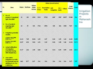
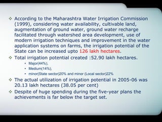
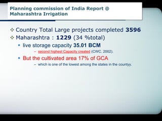
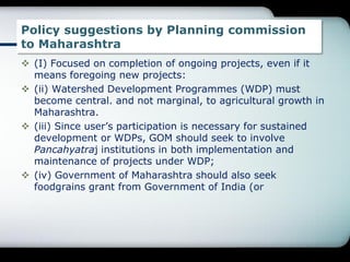
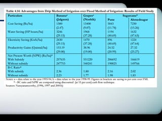
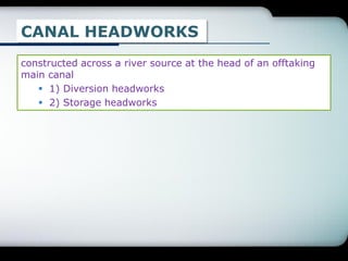
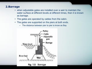
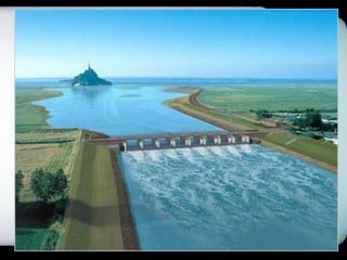
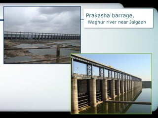
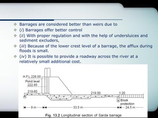
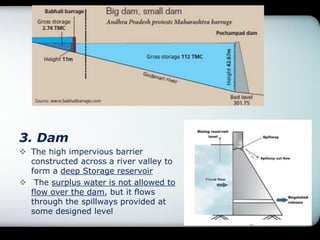
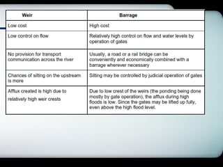
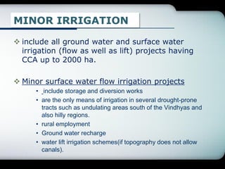
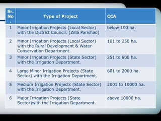
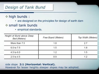
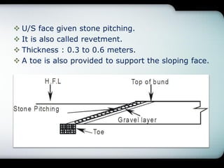
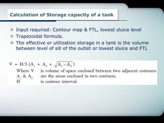
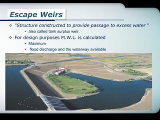
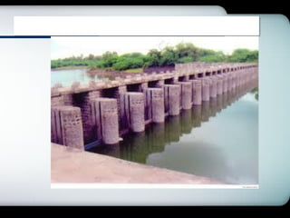
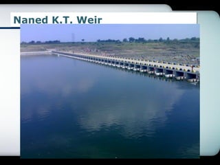
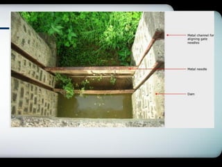
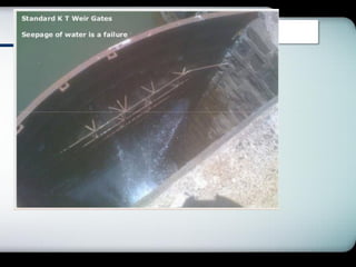
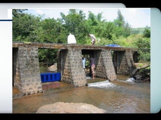
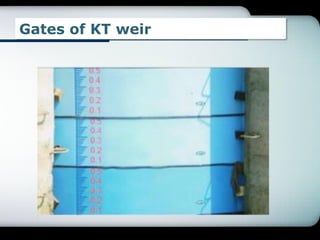
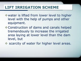
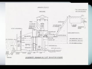
LOGO
5 A Minor Irrigation Works
( 5 hrs)
Irrigation
Projects
in
Maharash
tra
 According to the Maharashtra Water Irrigation Commission
(1999), considering water availability, cultivable land,
augmentation of ground water, ground water recharge
facilitated through watershed area development, use of
modern irrigation techniques and improvement in the water
application systems on farms, the irrigation potential of the
State can be increased upto 126 lakh hectares.
 Total irrigation potential created :52.90 lakh hectares.
• Major(44%),
• Medium(14%),
• minor(State sector)20% and minor (Local sector)22%
 The actual utilization of irrigation potential in 2005-06 was
20.13 lakh hectares (38.05 per cent)
 Despite of huge spending during the five-year plans the
achievements is far below the target set.
Planning commission of India Report @
Maharashtra Irrigation
 Country Total Large projects completed 3596
 Maharashtra : 1229 (34 %total)
 live storage capacity 35.01 BCM
– second highest Capacity created (CWC. 2002).
 But the cultivated area 17% of GCA
– which is one of the lowest among the states in the countyy.
Policy suggestions by Planning commission
to Maharashtra
 (I) Focused on completion of ongoing projects, even if it
means foregoing new projects:
 (ii) Watershed Development Programmes (WDP) must
become central. and not marginal, to agricultural growth in
Maharashtra.
 (iii) Since user‟s participation is necessary for sustained
development or WDPs, GOM should seek to involve
Pancahyatraj institutions in both implementation and
maintenance of projects under WDP;
 (iv) Government of Maharashtra should also seek
foodgrains grant from Government of India (or
CANAL HEADWORKS
constructed across a river source at the head of an offtaking
main canal
 1) Diversion headworks
 2) Storage headworks
Diversion headworks
 “divert the required supply from the source
channel to the offtaking channel.”
 The water level in the source channel is raised
to the required level so as to divert the required
supplies into the offtaking channel.
 should be capable of regulating the supplies.
 Arrangement for controlling the sediment entry.
 Most headworks in India are diversion headworks
which can be either temporary or permanent.
Stoarage headworks
 besides fulfilling all the requirements of diversion
headworks, store excess water when available
and release it during periods when demand
exceeds supplies
DIFFERENCE BETWEEN WEIR, BARRAGE AND DAM
1. Weir
 An impervious barrier which is constructed across a river to
raise the water level on the up stream side is known as weir.
 Here the water level is raised up to the required height and the
surplus water is allowed to flow over the weir. Generally it is
constructed across a inundation river
2.Barrage
• when adjustable gates are installed over a weir to maintain the
water surface at different levels at different times, then it is known
as barrage.
• The gates are operated by cables from the cabin.
• The gates are supported on the piers at both ends.
– The distance between pier to pier is know as Bay
Prakasha barrage,
Waghur river near Jalgaon
 Barrages are considered better than weirs due to
 (i) Barrages offer better control
 (ii) With proper regulation and with the help of undersluices and
sediment excluders,
 (iii) Because of the lower crest level of a barrage, the afflux during
floods is small.
 (iv) It is possible to provide a roadway across the river at a
relatively small additional cost.
3. Dam
 The high impervious barrier
constructed across a river valley to
form a deep Storage reservoir
 The surplus water is not allowed to
flow over the dam, but it flows
through the spillways provided at
some designed level
MINOR IRRIGATION
 include all ground water and surface water
irrigation (flow as well as lift) projects having
CCA up to 2000 ha.
 Minor surface water flow irrigation projects
• include storage and diversion works
• are the only means of irrigation in several drought-prone
tracts such as undulating areas south of the Vindhyas and
also hilly regions.
• rural employment
• Ground water recharge
• water lift irrigation schemes(if topography does not allow
canals).
Sr.
No
.
Type of Project CCA
1 Minor Irrigation Projects (Local Sector)
with the District Council. (Zilla Parishad)
below 100 ha.
2 Minor Irrigation Projects (Local Sector)
with the Rural Development & Water
Conservation Department.
101 to 250 ha.
3 Minor Irrigation Projects (State Sector)
with the Irrigation Department.
251 to 600 ha.
4 Large Minor Irrigation Projects (State
Sector) with the Irrigation Department.
601 to 2000 ha.
5 Medium Irrigation Projects (State Sector)
with the Irrigation Department.
2001 to 10000 ha.
6 Major Irrigation Projects (State
Sector)with the Irrigation Department.
above 10000 ha.
Sr. Well Irrigation Canal Irrigation
1 constructed gradually to keep pace
with the development
major structures, must be
constructed prior to the
start of proportionate
agricultural activity
2 Transit losses in well irrigation are
much less
3 Isolated patches of high lands can
be better served
4 reduces the chances of
waterlogging of canal-irrigated
lands.
5 relatively more reliable supply of
water at the time of need
(Cash crops)
6 needs energy for pumping.
Installation and maintenance,
operation cost of pumps
Conjunctive use in judicious manner is essential
Ground water irrigation
• Ground water
» widely distributed and provides an instant and assured
source of irrigation to farmers.
» controlling waterlogging and salination
» . Ground water development is
• It is mainly a cultivator’s own programme implemented
primarily through individual and cooperative efforts.
• Finance : through institutional sources.
• The first large-scale venture (1934)
» 1,500 tubewells in the Indo-Gangetic plains in the Meerut
region of UP
• Adequate energy is essential
» electricity and diesel, biogas-operated pumps ,photovoltaic
systems ,Wind energy
PERCOLATION TANK
• consists of earthen embankment and an overflow type masonry
waste weir.
• Permeable formation in the reservoir bed is an essential requirement
– acts as storage of intercepted runoff, which percolates down to phreatic aquifer creating a
recharge mound.
• Percolation time : permeability of bed formation.
– Between two consecutive rain spells, most of the storage percolates down.
• useful in area having sandstone and limestone formation underlying
• Tank is a general term used for surface water storage of moderate size.
Percolation tank/bund……
Percolation ponds
• interception of rainwater in a natural depression or
a manmade excavation.
Percolation tank
• by closing the openings of a natural saucer shaped
landform by constructing Earthen bunds sized
embankments.
• ED: less costly
• Technically bund is a miniature form of a dam.
TANKS
Classification
 4.5 meters height bunds :small tank.
 4.5- 9 m: Medium tanks
– very approximate because shape and size of the tank is not dependent on the
height of the bund alone. It is equally affected by the topographical features of the
region.
Network of Tanks
 as a separate entity or in the form of a group of
tanks in a series or tanks with inter-connection.
• (i) Isolated tanks;
• (ii) Tanks with inter-connection; and
• (iii) Tanks in series.
1. Isolated tanks:
• fed by an independent free draining catchment and the
surplus flows do not form network inflow into another tank,
• Mostly large and medium-large
2. Tanks with inter-connection:
• inter-connected tank group to receive flows through, as well
as deliver flows to, other tanks in the group severally.
• implies that the tanks have a combined catchment.
• surplus received is transferred to other tanks.
• Depending upon prevailing hydro-meteorological condition
the tanks are capable of feeding each other in reverse.
– Thus optimum water utilization
3. Tank in series:
• located alongside the river drainage channels.
• fed by inflow drains and serviced by escape or outflow
drains.
• Thus while the uppermost tanks have substantial free
catchment, the tanks lower down have limited free catchment
falling between two tanks.
• Advantage
– surplus water from the upper tank does not go waste but is
picked up by the lower tanks.
– Thus optimum water gets conserved.
• Disadvantage
– in case of breach in the upper tank, lower tanks also become
prone to severe flooding endangering safety of the tank bund.
– To avoid this, breaching sections
Definitions…
(i) Free catchment:
 If catchment of any dam/tank is not intercepted by
another structure
(ii) Breaching section:
 Overtopping of tank bund by floodwater is dangerous
 a natural saddle on the periphery of the tank is
selected.
• In the saddle, an ordinary retaining wall is constructed.
• Height is kept higher than FTL but lower than top of the tank
bund.
• If such a location is not available naturally breaching section
may be constructed at a suitable site away from the bund.
(iii) Escape channel:
 To carry the floodwater rushing out of the breached section
(iv) Full tank level (FTL):
 Normally full tank level (FTL) is governed by the top of the
escape or surplus weir.
 As soon as water level starts rising above this level, water starts
spilling over the weir.
(v) Maximum water level (MWL):
 level up to which the water may get stored temporarily in the tank
during high flood inflows.
 depends upon the waterway provided to pass flood discharge
safely.
 The top of bund is generally kept above this level by keeping
adequate free board.
Tank Bunds
Embankment of low height.
• Generally it is made of earth( mini E.D.).
Types:
• (a) Homogeneous Type
• (b) Zoned Type
• (c) Diaphragm Type
(a)Homogeneous Type: (Tank bund of Type A)
• uniform and homogeneous material
• relatively flat side slopes from consideration of stability.
• Most of the bunds belong to this type
 (b) Zoned Type: (Tank bund of Type B)
• When earth of different types is locally available the bund
may be constructed by dividing the section in different zones
• Outer zone(casing): pervious material. (murum)
• The inner zone(hearting): impervious material.(B.C. soil)
(c) Diaphragm Type: (Tank Bund of Type C)
• zoning is done by providing a central core wall, called
diaphragm.
• It is generally constructed with masonry or concrete
• taken quite deep in the foundation preferably up to
impervious stratum.
Types of Earthen Dams…US army mannual
Types of Rock fill Dams
Design of Tank Bund
 high bunds :
• are designed on the principles for design of earth dam
 small tank bunds
• empirical standards.
side slope 2:1 (Horizontal: Vertical).
However for lesser heights steeper slopes may be adopted.
 U/S face given stone pitching.
 It is also called revetment.
 Thickness : 0.3 to 0.6 meters.
 A toe is also provided to support the sloping face.
Calculation of Storage capacity of a tank
 Input required: Contour map & FTL, lowest sluice level
 Trapezoidal formula.
 The effective or utilization storage in a tank is the volume
between level of sill of the outlet or lowest sluice and FTL
Escape Weirs
 “Structure constructed to provide passage to excess water “
• also called tank surplus weir.
 For design purposes M.W.L. is calculated
• Maximum
• flood discharge and the waterway available
.
Selection of site for a tank weir
 (i) preferably a natural saddle away from the tank bund.
 (ii) Existence of a well-defined escape channel
 (iii) The saddle, where Natural Surface Level (NSL) is
approximately full tank level (FTL) should be given first
preference.
 (iv) Hard foundation if available at the site reduces the cost of
construction of bed protection work
 (v) When a site away from tank bund is not available, as far as
possible weir may be located on one end of the tank bund.
 (vi) Surplus weir may be housed in the body of the tank bund
only as a last resort.
 (vii) escape channel carrying surplussing water is not likely to
damage cultivated areas.
SYSTEM OF BANDHARA Irrigation
 Minor irrigation system suitable for irrigating isolated areas,
up to 500 hectares.
 similar to weir(brick masonry or stone masonry with R.C.C.
crest.)
 crest width :1 m to 2 m.
 Scouring sluices
• are provided at the
bottom of the bandhara
near the head reach of
the canal.
• They remove the silt
 The surplus water is allowed
to pass over the crest of the
bandhara.
 Thal : total area under a
bandhara
 Phad: Thai is divided
into several
 That's why, sometimes
this system is known as
„Phad irrigation system.‟
Site Selection
 (a) The banks of the stream should be high and well defined.
(b) The source of water should be reliable for constant supply.
(C) Stable foundation should be available for (he construction of
bandhara.
Advantages of Bandhara System
(a) The water of small streams can be utilized for irrigation
purpose by constructing a simple structure.
(b) The culturable area is generally close to the source. Hence
there is less possibility of transmission loss.
(C) As there is no loss due to transmission, evaporation and
percolation, the duty of water is high.
Disadvantages
(a) Normally, the discharge capacity of small streams is low.
people residing on the down stream side will not get water
for their use.
(b) The supply of water mainly depends on rainfall. So, in
the period of drought this system is practically useless.
Kolhapur Type Weir( Bandhara)
Irrigation in Maharashtra (Some Highlights)
 Phad system
 Malgujari Tanks in Vidarbha
• two centuries back
 Dams like Khadakwasla, Darna, Bhandaradara were
constructed before 1926
 Nira canal system is constructed way back around 1880 and is
functioning effectively even today.
 Radhanagari dam in Kolhapur districts
• was constructed by the then ruler of Kolhapur State and water is released
from this dam into the river and stored in series of Kolhapur Type
Weirs(popularly known as KT weirs) constructed on the rivers.
• Water released is lifted by members of co operative societies of farmers
and main crop of sugarcane is harvested in this area. These co-operative
societies have been functioning successfully for the last more than 80 years.
Naned K.T. Weir
Gates of KT weir
LIFT IRRIGATION SCHEME
water is lifted from lower level to higher
level with the help of pumps and other
equipment.
Construction of dams and canals helped
tremendously to increase the irrigated
area laying at lower level than the dam
level, but
 scarcity of water for higher level areas.
Advantages of L.I.S.
 irrigation possible at higher level.
 Land acquisition problem in L.I.S. is less.
 Water losses are low
Requirements of LIS
 Water Source: Suitable and constant water source should be
available for whole year
• . Water can be made available through Dams, K.T. Weir, River canal etc.
 Lifting Medium: To lift water to the desired location, lifting
medium i.e. pumps are required. Depending upon the Duty point
head discharge the different types of pumps are selected.
 Conveying Medium: Rising main may be of steel, concrete or any
other suitable material.
Minor Irrigation for water resources engineering

Minor Irrigation for water resources engineering

  • 1.
    LOGO 5 A MinorIrrigation Works ( 5 hrs)
  • 2.
  • 3.
     According tothe Maharashtra Water Irrigation Commission (1999), considering water availability, cultivable land, augmentation of ground water, ground water recharge facilitated through watershed area development, use of modern irrigation techniques and improvement in the water application systems on farms, the irrigation potential of the State can be increased upto 126 lakh hectares.  Total irrigation potential created :52.90 lakh hectares. • Major(44%), • Medium(14%), • minor(State sector)20% and minor (Local sector)22%  The actual utilization of irrigation potential in 2005-06 was 20.13 lakh hectares (38.05 per cent)  Despite of huge spending during the five-year plans the achievements is far below the target set.
  • 4.
    Planning commission ofIndia Report @ Maharashtra Irrigation  Country Total Large projects completed 3596  Maharashtra : 1229 (34 %total)  live storage capacity 35.01 BCM – second highest Capacity created (CWC. 2002).  But the cultivated area 17% of GCA – which is one of the lowest among the states in the countyy.
  • 5.
    Policy suggestions byPlanning commission to Maharashtra  (I) Focused on completion of ongoing projects, even if it means foregoing new projects:  (ii) Watershed Development Programmes (WDP) must become central. and not marginal, to agricultural growth in Maharashtra.  (iii) Since user‟s participation is necessary for sustained development or WDPs, GOM should seek to involve Pancahyatraj institutions in both implementation and maintenance of projects under WDP;  (iv) Government of Maharashtra should also seek foodgrains grant from Government of India (or
  • 7.
    CANAL HEADWORKS constructed acrossa river source at the head of an offtaking main canal  1) Diversion headworks  2) Storage headworks
  • 10.
    Diversion headworks  “divertthe required supply from the source channel to the offtaking channel.”  The water level in the source channel is raised to the required level so as to divert the required supplies into the offtaking channel.  should be capable of regulating the supplies.  Arrangement for controlling the sediment entry.  Most headworks in India are diversion headworks which can be either temporary or permanent. Stoarage headworks  besides fulfilling all the requirements of diversion headworks, store excess water when available and release it during periods when demand exceeds supplies
  • 11.
    DIFFERENCE BETWEEN WEIR,BARRAGE AND DAM 1. Weir  An impervious barrier which is constructed across a river to raise the water level on the up stream side is known as weir.  Here the water level is raised up to the required height and the surplus water is allowed to flow over the weir. Generally it is constructed across a inundation river
  • 12.
    2.Barrage • when adjustablegates are installed over a weir to maintain the water surface at different levels at different times, then it is known as barrage. • The gates are operated by cables from the cabin. • The gates are supported on the piers at both ends. – The distance between pier to pier is know as Bay
  • 14.
  • 15.
     Barrages areconsidered better than weirs due to  (i) Barrages offer better control  (ii) With proper regulation and with the help of undersluices and sediment excluders,  (iii) Because of the lower crest level of a barrage, the afflux during floods is small.  (iv) It is possible to provide a roadway across the river at a relatively small additional cost.
  • 16.
    3. Dam  Thehigh impervious barrier constructed across a river valley to form a deep Storage reservoir  The surplus water is not allowed to flow over the dam, but it flows through the spillways provided at some designed level
  • 18.
    MINOR IRRIGATION  includeall ground water and surface water irrigation (flow as well as lift) projects having CCA up to 2000 ha.  Minor surface water flow irrigation projects • include storage and diversion works • are the only means of irrigation in several drought-prone tracts such as undulating areas south of the Vindhyas and also hilly regions. • rural employment • Ground water recharge • water lift irrigation schemes(if topography does not allow canals).
  • 19.
    Sr. No . Type of ProjectCCA 1 Minor Irrigation Projects (Local Sector) with the District Council. (Zilla Parishad) below 100 ha. 2 Minor Irrigation Projects (Local Sector) with the Rural Development & Water Conservation Department. 101 to 250 ha. 3 Minor Irrigation Projects (State Sector) with the Irrigation Department. 251 to 600 ha. 4 Large Minor Irrigation Projects (State Sector) with the Irrigation Department. 601 to 2000 ha. 5 Medium Irrigation Projects (State Sector) with the Irrigation Department. 2001 to 10000 ha. 6 Major Irrigation Projects (State Sector)with the Irrigation Department. above 10000 ha.
  • 20.
    Sr. Well IrrigationCanal Irrigation 1 constructed gradually to keep pace with the development major structures, must be constructed prior to the start of proportionate agricultural activity 2 Transit losses in well irrigation are much less 3 Isolated patches of high lands can be better served 4 reduces the chances of waterlogging of canal-irrigated lands. 5 relatively more reliable supply of water at the time of need (Cash crops) 6 needs energy for pumping. Installation and maintenance, operation cost of pumps Conjunctive use in judicious manner is essential
  • 21.
    Ground water irrigation •Ground water » widely distributed and provides an instant and assured source of irrigation to farmers. » controlling waterlogging and salination » . Ground water development is • It is mainly a cultivator’s own programme implemented primarily through individual and cooperative efforts. • Finance : through institutional sources. • The first large-scale venture (1934) » 1,500 tubewells in the Indo-Gangetic plains in the Meerut region of UP • Adequate energy is essential » electricity and diesel, biogas-operated pumps ,photovoltaic systems ,Wind energy
  • 22.
    PERCOLATION TANK • consistsof earthen embankment and an overflow type masonry waste weir. • Permeable formation in the reservoir bed is an essential requirement – acts as storage of intercepted runoff, which percolates down to phreatic aquifer creating a recharge mound. • Percolation time : permeability of bed formation. – Between two consecutive rain spells, most of the storage percolates down. • useful in area having sandstone and limestone formation underlying • Tank is a general term used for surface water storage of moderate size.
  • 24.
    Percolation tank/bund…… Percolation ponds •interception of rainwater in a natural depression or a manmade excavation. Percolation tank • by closing the openings of a natural saucer shaped landform by constructing Earthen bunds sized embankments. • ED: less costly • Technically bund is a miniature form of a dam.
  • 25.
    TANKS Classification  4.5 metersheight bunds :small tank.  4.5- 9 m: Medium tanks – very approximate because shape and size of the tank is not dependent on the height of the bund alone. It is equally affected by the topographical features of the region. Network of Tanks  as a separate entity or in the form of a group of tanks in a series or tanks with inter-connection. • (i) Isolated tanks; • (ii) Tanks with inter-connection; and • (iii) Tanks in series.
  • 26.
    1. Isolated tanks: •fed by an independent free draining catchment and the surplus flows do not form network inflow into another tank, • Mostly large and medium-large 2. Tanks with inter-connection: • inter-connected tank group to receive flows through, as well as deliver flows to, other tanks in the group severally. • implies that the tanks have a combined catchment. • surplus received is transferred to other tanks. • Depending upon prevailing hydro-meteorological condition the tanks are capable of feeding each other in reverse. – Thus optimum water utilization
  • 27.
    3. Tank inseries: • located alongside the river drainage channels. • fed by inflow drains and serviced by escape or outflow drains. • Thus while the uppermost tanks have substantial free catchment, the tanks lower down have limited free catchment falling between two tanks. • Advantage – surplus water from the upper tank does not go waste but is picked up by the lower tanks. – Thus optimum water gets conserved. • Disadvantage – in case of breach in the upper tank, lower tanks also become prone to severe flooding endangering safety of the tank bund. – To avoid this, breaching sections
  • 28.
    Definitions… (i) Free catchment: If catchment of any dam/tank is not intercepted by another structure (ii) Breaching section:  Overtopping of tank bund by floodwater is dangerous  a natural saddle on the periphery of the tank is selected. • In the saddle, an ordinary retaining wall is constructed. • Height is kept higher than FTL but lower than top of the tank bund. • If such a location is not available naturally breaching section may be constructed at a suitable site away from the bund.
  • 29.
    (iii) Escape channel: To carry the floodwater rushing out of the breached section (iv) Full tank level (FTL):  Normally full tank level (FTL) is governed by the top of the escape or surplus weir.  As soon as water level starts rising above this level, water starts spilling over the weir. (v) Maximum water level (MWL):  level up to which the water may get stored temporarily in the tank during high flood inflows.  depends upon the waterway provided to pass flood discharge safely.  The top of bund is generally kept above this level by keeping adequate free board.
  • 30.
    Tank Bunds Embankment oflow height. • Generally it is made of earth( mini E.D.). Types: • (a) Homogeneous Type • (b) Zoned Type • (c) Diaphragm Type
  • 31.
    (a)Homogeneous Type: (Tankbund of Type A) • uniform and homogeneous material • relatively flat side slopes from consideration of stability. • Most of the bunds belong to this type
  • 32.
     (b) ZonedType: (Tank bund of Type B) • When earth of different types is locally available the bund may be constructed by dividing the section in different zones • Outer zone(casing): pervious material. (murum) • The inner zone(hearting): impervious material.(B.C. soil)
  • 33.
    (c) Diaphragm Type:(Tank Bund of Type C) • zoning is done by providing a central core wall, called diaphragm. • It is generally constructed with masonry or concrete • taken quite deep in the foundation preferably up to impervious stratum.
  • 34.
    Types of EarthenDams…US army mannual
  • 36.
    Types of Rockfill Dams
  • 37.
    Design of TankBund  high bunds : • are designed on the principles for design of earth dam  small tank bunds • empirical standards. side slope 2:1 (Horizontal: Vertical). However for lesser heights steeper slopes may be adopted.
  • 38.
     U/S facegiven stone pitching.  It is also called revetment.  Thickness : 0.3 to 0.6 meters.  A toe is also provided to support the sloping face.
  • 39.
    Calculation of Storagecapacity of a tank  Input required: Contour map & FTL, lowest sluice level  Trapezoidal formula.  The effective or utilization storage in a tank is the volume between level of sill of the outlet or lowest sluice and FTL
  • 40.
    Escape Weirs  “Structureconstructed to provide passage to excess water “ • also called tank surplus weir.  For design purposes M.W.L. is calculated • Maximum • flood discharge and the waterway available .
  • 41.
    Selection of sitefor a tank weir  (i) preferably a natural saddle away from the tank bund.  (ii) Existence of a well-defined escape channel  (iii) The saddle, where Natural Surface Level (NSL) is approximately full tank level (FTL) should be given first preference.  (iv) Hard foundation if available at the site reduces the cost of construction of bed protection work  (v) When a site away from tank bund is not available, as far as possible weir may be located on one end of the tank bund.  (vi) Surplus weir may be housed in the body of the tank bund only as a last resort.  (vii) escape channel carrying surplussing water is not likely to damage cultivated areas.
  • 43.
    SYSTEM OF BANDHARAIrrigation  Minor irrigation system suitable for irrigating isolated areas, up to 500 hectares.  similar to weir(brick masonry or stone masonry with R.C.C. crest.)
  • 45.
     crest width:1 m to 2 m.  Scouring sluices • are provided at the bottom of the bandhara near the head reach of the canal. • They remove the silt  The surplus water is allowed to pass over the crest of the bandhara.  Thal : total area under a bandhara  Phad: Thai is divided into several  That's why, sometimes this system is known as „Phad irrigation system.‟
  • 46.
    Site Selection  (a)The banks of the stream should be high and well defined. (b) The source of water should be reliable for constant supply. (C) Stable foundation should be available for (he construction of bandhara. Advantages of Bandhara System (a) The water of small streams can be utilized for irrigation purpose by constructing a simple structure. (b) The culturable area is generally close to the source. Hence there is less possibility of transmission loss. (C) As there is no loss due to transmission, evaporation and percolation, the duty of water is high.
  • 47.
    Disadvantages (a) Normally, thedischarge capacity of small streams is low. people residing on the down stream side will not get water for their use. (b) The supply of water mainly depends on rainfall. So, in the period of drought this system is practically useless.
  • 48.
    Kolhapur Type Weir(Bandhara) Irrigation in Maharashtra (Some Highlights)  Phad system  Malgujari Tanks in Vidarbha • two centuries back  Dams like Khadakwasla, Darna, Bhandaradara were constructed before 1926  Nira canal system is constructed way back around 1880 and is functioning effectively even today.  Radhanagari dam in Kolhapur districts • was constructed by the then ruler of Kolhapur State and water is released from this dam into the river and stored in series of Kolhapur Type Weirs(popularly known as KT weirs) constructed on the rivers. • Water released is lifted by members of co operative societies of farmers and main crop of sugarcane is harvested in this area. These co-operative societies have been functioning successfully for the last more than 80 years.
  • 52.
  • 56.
  • 57.
    LIFT IRRIGATION SCHEME wateris lifted from lower level to higher level with the help of pumps and other equipment. Construction of dams and canals helped tremendously to increase the irrigated area laying at lower level than the dam level, but  scarcity of water for higher level areas.
  • 59.
    Advantages of L.I.S. irrigation possible at higher level.  Land acquisition problem in L.I.S. is less.  Water losses are low Requirements of LIS  Water Source: Suitable and constant water source should be available for whole year • . Water can be made available through Dams, K.T. Weir, River canal etc.  Lifting Medium: To lift water to the desired location, lifting medium i.e. pumps are required. Depending upon the Duty point head discharge the different types of pumps are selected.  Conveying Medium: Rising main may be of steel, concrete or any other suitable material.