1. www. .com
36
March 2014
MAPPING & SURVEYING
G
round-penetrating radar, also
known as ground-probing radar,
georadar or GPR, has been
successfully used as a geophysical tool
for over 40 years. In the past two dec-
ades, GPR’s popularity in mining applica-
tions has been growing as a result of
technological advancements, the ability
to obtain high-resolution data easily and
efficiently, and the overall perceived high
return on investment.
Accuracy, survey speed and real-time
results of GPR systems provide quick and
valuable information for mining
professionals to make informed
decisions that optimise various
applications, such as mine safety, mineral
exploration, mapping geological
features and determining rock quality.
HOW GPR WORKS
GPR works by sending a pulse of energy
from an antenna into a material and
recording the strength and the travel
time required for the return of any
reflected signals. A series of pulses over
a single area make up what is called a
single scan.
Reflections are produced whenever
the velocity of the energy pulse changes,
caused by transitioning into a material
with different electrical conductive
properties or dielectric permittivity. The
strength, or amplitude, of the reflection
is determined by the contrast in the
dielectric constants and conductivities of
the two materials. For example, a pulse
that transitioned from salt (having low
dielectric permittivity) into shale (with
high dielectric permittivity) will produce
a very strong reflection, while one
moving from dry sand (low dielectric) to
limestone (with a similar low dielectric)
will produce a very weak reflection.
While some GPR energy is reflected
back to the antenna, energy also
continues to travel through the material
until the pulse signal is completely
attenuated or blocked by a metallic
substance. The rate of signal attenuation
varies widely and is dependent on the
dielectric properties of the material
through which the pulse is passing.
THE GPR SYSTEM
Every GPR system has three main
components: a control unit, a GPR
antenna and a power supply. The control
unit displays and stores the real-time
data and contains the electronics which
trigger the pulse of radar energy that the
antenna sends into the ground. It may
have a built-in computer and hard disk/
solid-state memory to store data for
examination after fieldwork.
Some systems can be controlled
remotely by an external laptop
computer, which can be beneficial for
mounting of the GPR system on vehicles.
The antenna receives the electrical pulse
produced by the control unit, amplifies it
and transmits it into the ground or other
medium at a particular frequency.
Antenna frequency is the major factor
in resolution and depth penetration; the
higher the frequency of the antenna, the
shallower into the ground it will
penetrate. However, a higher-frequency
antenna can resolve smaller targets or
thinner layers. The lower the frequency
of the antenna, the deeper into the
ground it will penetrate. A lower-fre-
quency antenna will penetrate deeper,
but cannot provide the same resolution
as a high-frequency antenna. Antenna
selection is one of the most important
factors in survey design. GPR antenna
frequencies typically range from 16MHz
to 2GHz.
GPR equipment can be operated with
a variety of power supplies ranging from
small rechargeable batteries to vehicle
batteries and normal 110/220V supplies.
Connectors and adapters are available
for each power-source type so that the
GPR equipment can be used in a wide
range of setups – mounted on small
portable survey carts, used on lifts or
special trailers, or located on vehicles.
GPR FOR MINING APPLICATIONS
Salt/potash mining
GPR is used by a number of leading salt
and potash mining companies in the US
and Canada. Salt (halite) and potash are
excellent candidates for the application
of GPR technology because they have
low dielectric permittivity and the
equipment can image deeply while still
offering high resolution.
GSSI has found that its most common
equipment used at these types of mines
include an SIR-3000, SIR-20 or SIR-30
control unit, a 2GHz air-launched horn
antenna and a 400MHz ground-coupled
antenna.
The 2GHz air-launched horn antenna
offers superior resolution for determining
the overhead thickness of the salt/potash
to shale markers, as well as locating
separations at the shale boundary and
other potential safety concerns, such as
fractures or thinning/thickening of shale
Exploration… and beyond
Jami Harmon and Brian Jones look at the application of ground-penetrating radar in the mining industry
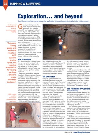
Underground
mines often use
GPR for
overhead safety
mapping
GPR is often
used for
mapping at
potash and salt
operations
“Accuracy,
survey
speed and
real-time
results of
GPR
systems
provide
quick and
valuable
information
for mining
profess-
ionals to
make
informed
decisions”
Mapping/Exploration...andbeyond(GSSI)_MM1403.indd 36 14/02/2014 15:30
2. 37
www. .com March 2014
MAPPING & SURVEYING
layers (see Figure 1). The lower-frequency
400MHz ground-coupled antenna can be
used for layer or anomaly mapping at
depths greater than 15m.
Data is often collected using common
mining vehicles with a trailer for floor
mapping, or a lift setup so that the GPR
antenna can be elevated near the back;
however, simple setups pulled (or pushed)
along by an individual are used too.
The use of drilling and blasting
techniques or continuous miners is often
done somewhat blindly with limited
geological knowledge, which can lead to
the removal of too much material
(causing safety or impurity issues), or not
enough material to optimise profits. The
use of GPR not only helps salt and
potash mining professionals determine
current and potentially future safety
concerns, but it can also be used to aid
in maximising extraction.
Mine planning
GPR is a highly effective mapping tool
for mine planning and exploration
applications, such as locating problem-
atic areas to avoid before they are
exposed, or mapping features of interest
to head towards, such as mineralised
veins. The GPR profile shown in Figure 2
is from a limestone-mining operation in
Iowa, US. Data was collected using a
GSSI SIR-3000 control unit and 400MHz
antenna.
The GPR technology was used at this
mine to quickly and accurately
determine limestone thickness as it
relates to vertical inclusions, or simply to
map the presence of shale inclusions
prior to the mining process. This allowed
the company to plan where to continue
mining, as proceeding towards the
inclusion would be a costly waste of
time, money and resources when the aim
is to produce a high-grade limestone
product.
GPR data used for planning purposes
is typically correlated to visible exposures
or test-drill locations and then used to
identify further areas of interest
throughout the mine. This technique can
save considerable time and money that
might have otherwise been used to drill
numerous, unnecessary exploratory holes.
GPR can map hundreds of metres a
day and can give a continuous profile of
what is beyond the surface, whereas
core or drill holes offer much more
limited information. Also, a destructive
approach such as drilling or coring can
often lead to other unwanted conse-
quences, such as exposing water.
Hazard assessment
Mining in general offers countless
hazards that need to be managed and
avoided on a daily basis. GPR can offer
mining engineers another tool to help
tackle these hazards and effectively
remediate or eliminate them before a
costly issue arises.
For example, a leading mining
company in Chile requested a
demonstration from GSSI to identify
problem areas that could negatively
affect mine safety.
GSSI employed a SIR-3000 control
unit with a 200MHz antenna to survey a
terrace flight in an open-pit mine to
check for voids and/or unconsolidated
material, the presence of which could
imperil large trucks. Problems such as
these could go unknown for years until
a major issue occurs that can lead to
damage to vehicles or worse.
Another example from the under-
ground coal-mining industry is what is
commonly referred to as ‘rock bursts’,
or the violent fracture of rock under
pressure.
GPR can be used to locate potential
rock-burst locations by mapping
fractures and anomalies within the
bedded material. Figure 3 shows a
200MHz GPR profile of such potential
zones. This information could be used
to plan support structures or preventa-
tive measures to ensure the safety of
workers.
Mineral exploration
Mining professionals can use GPR for
mineral exploration in igneous and
metamorphic rock formations. The
technology can be used to map
hydrothermal veins and pegmatites, as
well as locate cavities and vugs housing
crystals that could otherwise be difficult
and time-consuming to pinpoint with
traditional drilling and blasting
techniques.
Using 2-D or even 3-D imagery the
features of interest can be precisely
detected. For instance, GPR was used
to locate a cavity that ended up as
home to one of the largest emerald
crystals found in North America.
Jami Harmon is marketing communications manager and Brian Jones is an application specialist, both at Geophysical Survey Systems Inc (GSSI), a world
leader in the development and manufacture of subsurface imaging products. See www.geophysical.com
Figure 1: data
profile from a
2GHz horn
antenna showing
separations at
the salt/shale
interface, as well
as an
intermittent
shale seam
Figure 2: GPR
data illustrates a
divide in material
layers (defined
by a red line).
Above the line is
limestone, below
is the shale/
sandstone
inclusion mix
Figure 3:
200MHz antenna
data profile
showing
potential rock-
burst zones
within the
layered material
“Antenna
selection
is one of
the most
important
factors in
survey
design”
Mapping/Exploration...andbeyond(GSSI)_MM1403.indd 37 14/02/2014 15:30