Downloaded 1,164 times


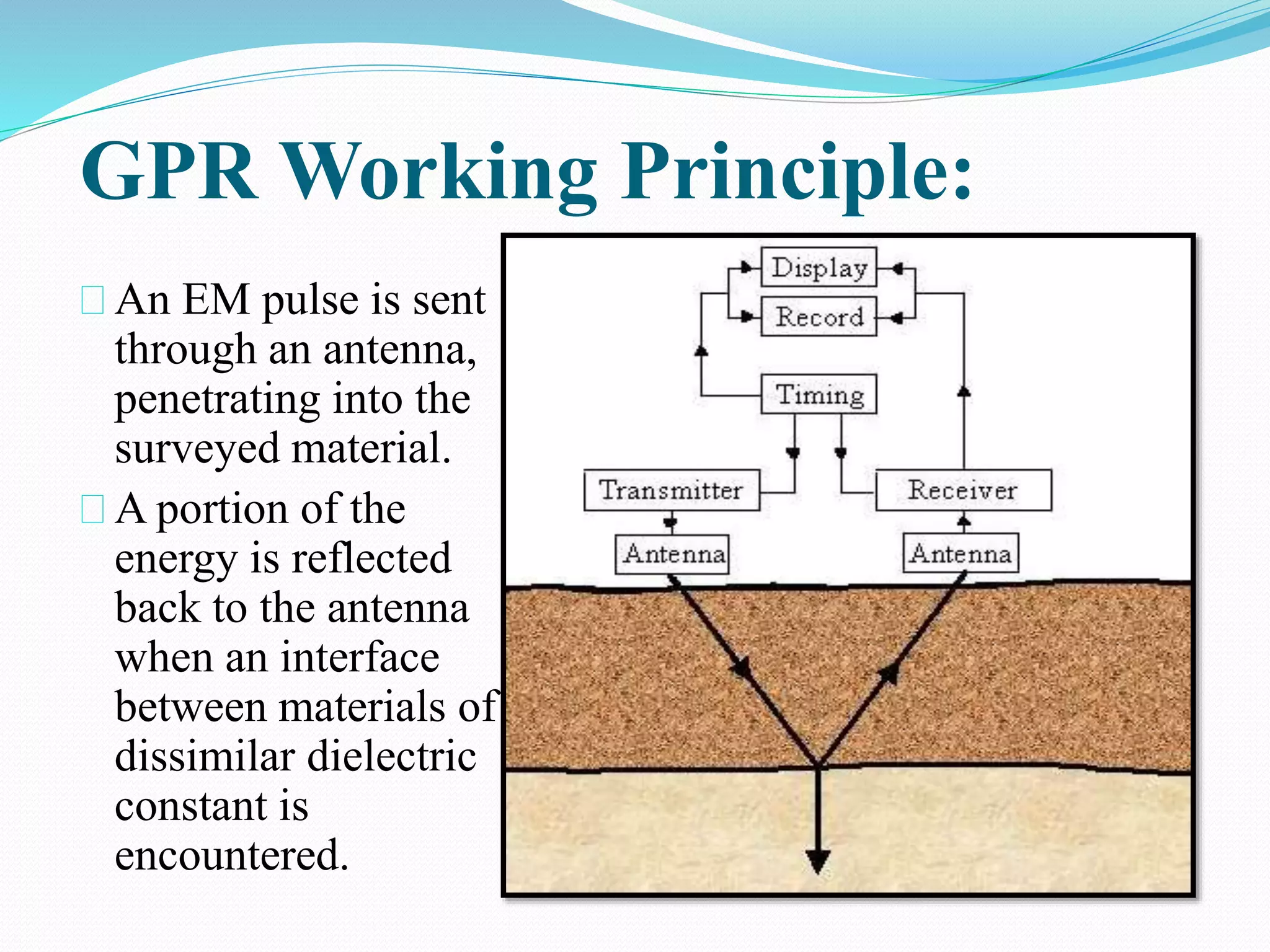


The seminar presentation on Ground Penetrating Radar (GPR) covers its introduction, components, working principles, advantages, and applications. GPR is a non-invasive geophysical method that utilizes radar pulses to detect subsurface features in various media, allowing for the identification of buried objects and voids. It has diverse applications in fields such as earth sciences, military operations, and utility location, providing detailed images of both metallic and non-metallic structures.


