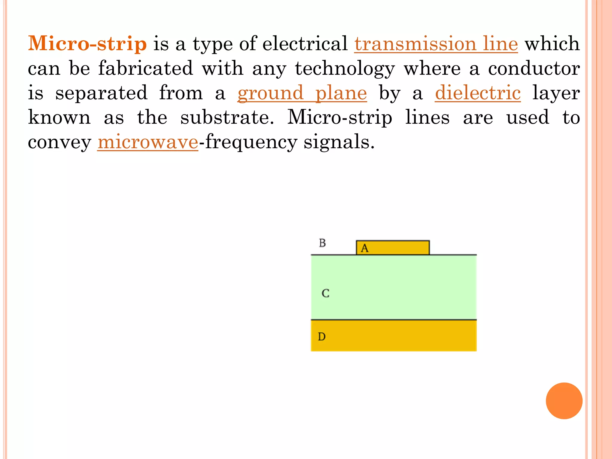
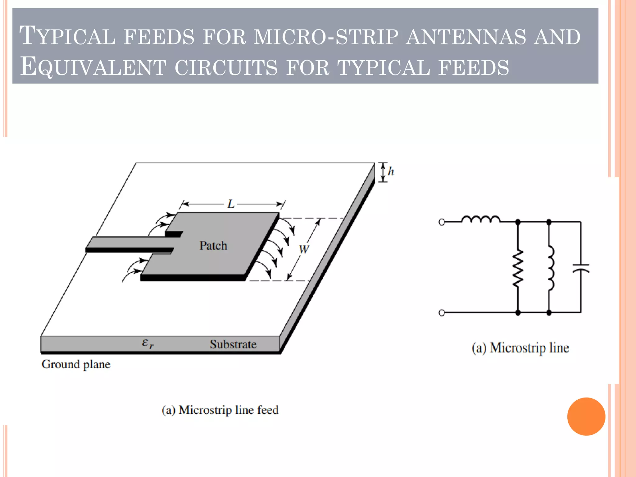
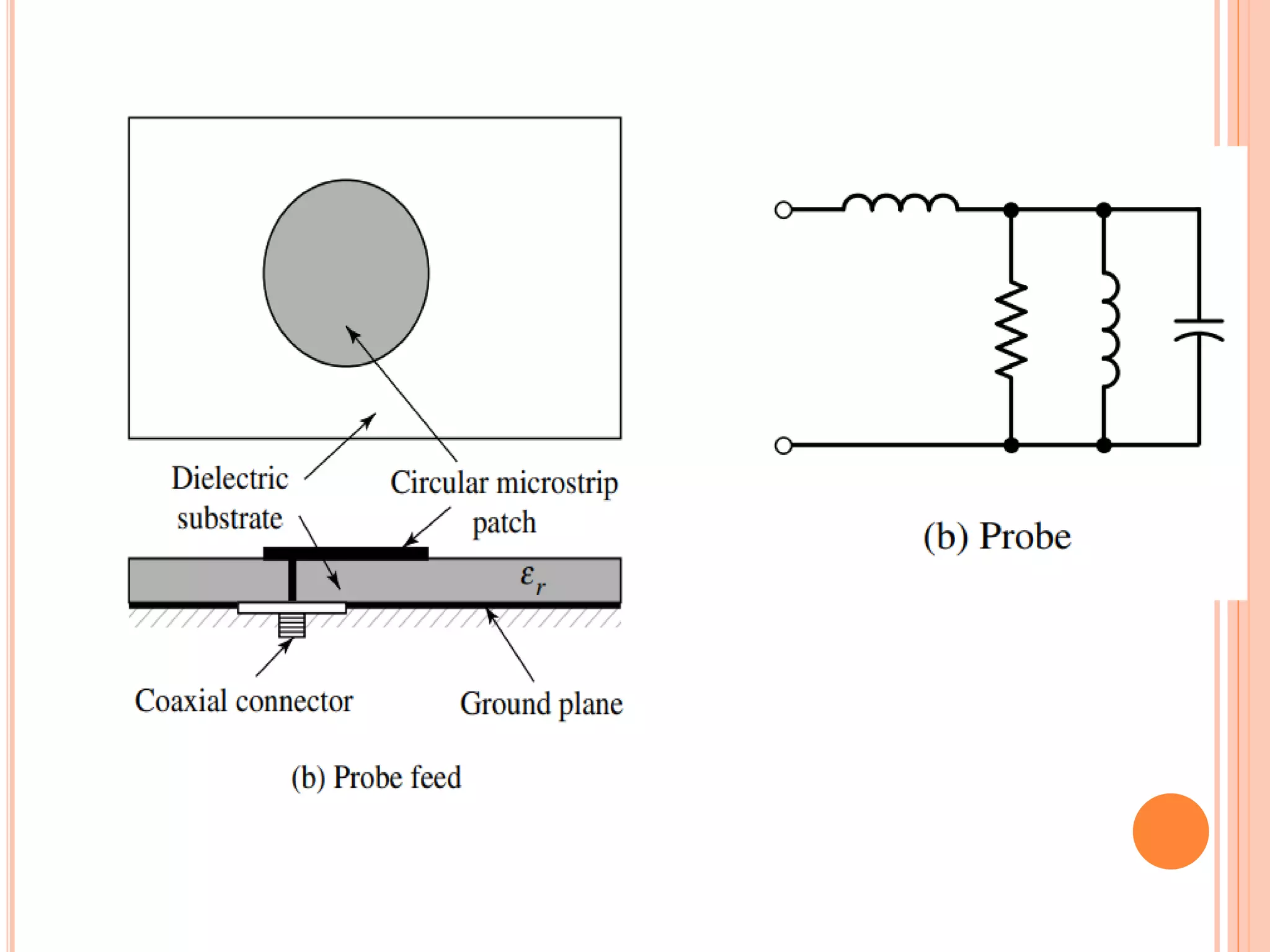
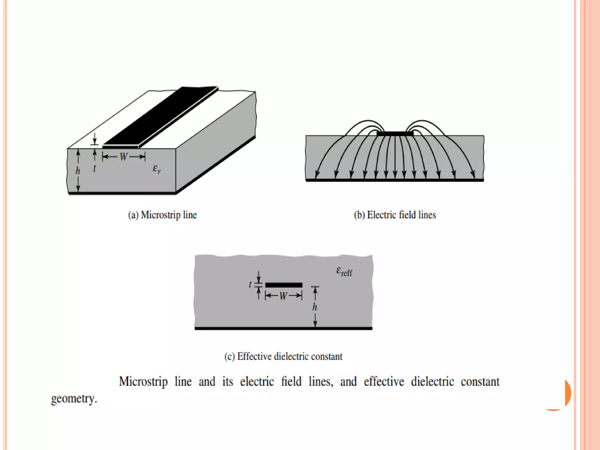
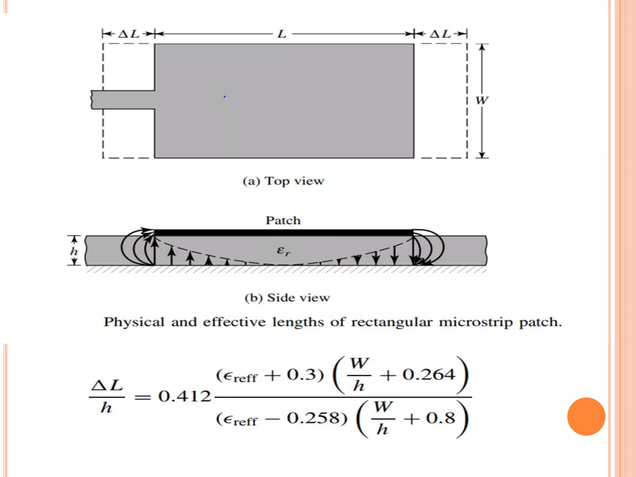
Micro-strip antennas consist of a conducting patch on a dielectric substrate backed by a ground plane. They are inexpensive to produce and can be fabricated using printed circuit board technology. The patch shape is typically rectangular and can be analyzed using transmission line models. Key design considerations include the effective dielectric constant which influences the resonant frequency, as well as fringing effects along the patch edges which affect the patch length. A common design procedure specifies the resonant frequency, substrate properties, and calculates the appropriate patch dimensions.
This ppt describes the ways of designing a fractal antenna , it's limitations and advantages over normal antennas and the applications associated with it.(brief view)...
HFSS ANTENNA FOR KU BAND WITH DEFECTED GROUND STRUCTURESAKSHAT GANGWAR
A wide band Microstrip antenna is proposed for Ku band applications with defected groundd structure. A circular shape defect is integrated in the ground plane. A novel equivalent circuit model is proposed for Microstrip patch antenna with defected ground structure. Accurate design equations are presented for the wideband Microstrip antenna and theoretical analysis is done for the proposed structure. The proposed antenna has an impedance bandwidth of 56.67% ranging from 9.8 GHz to 17.55 GHz, which covers Ku-band and partially X-band. The antenna shows good radiation characteristics within the entire band, and has a gain ranging from 5 dBi to 12.08 dBi. Minimum isolation between co-polar and cross-polarization level of 20 dB and 15 dB is achieved in H-plane and E-plane respectively. The simulation of the proposed antenna is done on HFSS v.13, and measured results of fabricated antenna are in good agreement with the theoretical and simulated results
Analyzing the Different Parameters of Dipole AntennaIJEEE
Ultra wideband is a wireless technology to realize high speed communications which is performed in wideband. In this paper the wideband dipole antenna is designed.
A horn may be considered as a flared out waveguide. In this paper, a powerful electromagnetic simulator, 3D
EM solver WIPL-D software is used to design, analyse and optimize the dimensions of horn antenna which is
based on MOM solution for computations. The standard horn antenna at 10 GHz for 15dB gain is modelled and
the radiation pattern was observed. The horn antenna is optimized to achieve more than 20dB gain using
Genetic Algorithm, radiation patterns of the optimized horn antenna are also presented. Geometry of the horn
can be modelled by exploring the toolbar ‘symmetry’ option in WIPL-D. Design of X band Pyramidal Horn
Antenna is fabricated and measured using Network Analyzer.
This paper presents the idea of recent developments and advancements in the field of wireless technology to realize high speed communications which is performed in wideband technology .In this paper the wideband patch antenna is designed and fabricated.
International Refereed Journal of Engineering and Science (IRJES)irjes
International Refereed Journal of Engineering and Science (IRJES) is a leading international journal for publication of new ideas, the state of the art research results and fundamental advances in all aspects of Engineering and Science. IRJES is a open access, peer reviewed international journal with a primary objective to provide the academic community and industry for the submission of half of original research and applications
International Refereed Journal of Engineering and Science (IRJES) is a peer reviewed online journal for professionals and researchers in the field of computer science. The main aim is to resolve emerging and outstanding problems revealed by recent social and technological change. IJRES provides the platform for the researchers to present and evaluate their work from both theoretical and technical aspects and to share their views.
Dual band microstrip antenna with slit load design for wireless local area ne...BASIM AL-SHAMMARI
This paper presents a design of dual frequency band operation nearly square patch antenna
for IEEE 802.11b,g (2.4Ghz-2.4835GHz) and IEEE 802.11a (5.15GHz-5.25GHz)by using a patch
antenna. The patch and ground plane are separated by a substrate; the radiating patch have two pairs
of orthogonal slits cut from the edge, this antenna has wide bandwidth in the frequency band of
(WLAN) and with a return loss ≤ −10 dB from 2.4 GHz to 2.48 GHz and from 5.12 GHz to 5.32
GHz exhibits circularly polarized far-field radiation pattern. The proposed antennas have been
simulated and analyzed using method of moments (MoM) based software package Microwave
Office 2009 v9.0. The results show that the antenna has dual-band frequency operation by using slit
load.
Dual band microstrip antenna with slit load design for wireless local area ne...BASIM AL-SHAMMARI
This paper presents a design of dual frequency band operation nearly square patch antenna
for IEEE 802.11b,g (2.4Ghz-2.4835GHz) and IEEE 802.11a (5.15GHz-5.25GHz)by using a patch
antenna. The patch and ground plane are separated by a substrate; the radiating patch have two pairs
of orthogonal slits cut from the edge, this antenna has wide bandwidth in the frequency band of
(WLAN) and with a return loss ≤ −10 dB from 2.4 GHz to 2.48 GHz and from 5.12 GHz to 5.32
GHz exhibits circularly polarized far field radiation pattern. The proposed antennas have been
simulated and analyzed using method of moments (MoM) based software package Microwave
Office 2009 v9.0. The results show that the antenna has dual band frequency operation by using slit
load.
Rectangular and circular antennas design for Bluetooth applicationsTELKOMNIKA JOURNAL
The most researched and examined aspect of the communication system is the wireless connection. Without learning how to operate and use different types of antennas, your knowledge is incomplete. Microstrip patch antenna research has advanced significantly in recent years. When compared to standard antennas, microstrip patch antennas provide additional advantages and opportunities. It is of low volume, light weight, low cost, low appearance, compact and easy to manufacture. This study investigates the differences between rectangular and circular patch antennas. For Bluetooth applications, the center frequency of 2.4 GHz was chosen as the optimal resonant frequency. On a flame retardant (FR-4) epoxy substrate, the antenna dielectric constant is 4.4. Above the ground the base rises 3.6 mm. For the simulation process, high frequency simulation software (HFSS 15) is used as the program design. Antennas 1×1, 1×2, and 1×4 are designed for both circular and rectangular antennas. A comparison was made for both types of antennas and voltage standing wave ratio (VSWR), return losses, gain, directivity and half power beam width (HPBW) were found, and the feature of the rectangular antenna was shown.
It was our first real life based designing experience on this platform. From the mentioned designed we tried to develop a prototype of Dipole antenna of 600 Mhz for practical uses. For the further development we’ve a got plan to use a simulation software like CST microwave studio or ADS to simulate our developed design in the long term . We had to work very hard to complete this design in time! But in the end, the challenge and learning experience were well worth it.
Analysis of Co-Axial Cable Response to 700m Long Digital Data Transmission.iosrjce
IOSR Journal of Electrical and Electronics Engineering(IOSR-JEEE) is a double blind peer reviewed International Journal that provides rapid publication (within a month) of articles in all areas of electrical and electronics engineering and its applications. The journal welcomes publications of high quality papers on theoretical developments and practical applications in electrical and electronics engineering. Original research papers, state-of-the-art reviews, and high quality technical notes are invited for publications.
International Journal of Engineering Research and Applications (IJERA) is a team of researchers not publication services or private publications running the journals for monetary benefits, we are association of scientists and academia who focus only on supporting authors who want to publish their work. The articles published in our journal can be accessed online, all the articles will be archived for real time access.
Our journal system primarily aims to bring out the research talent and the works done by sciaentists, academia, engineers, practitioners, scholars, post graduate students of engineering and science. This journal aims to cover the scientific research in a broader sense and not publishing a niche area of research facilitating researchers from various verticals to publish their papers. It is also aimed to provide a platform for the researchers to publish in a shorter of time, enabling them to continue further All articles published are freely available to scientific researchers in the Government agencies,educators and the general public. We are taking serious efforts to promote our journal across the globe in various ways, we are sure that our journal will act as a scientific platform for all researchers to publish their works online.
Comparison between Rectangular and Circular Patch Antennas Arrayijceronline
In this paper, several designs of micorstip arrays antennas, suitable for wireless communication applications, are presented. This paper demonstratesseveral shapesof microstrip array antennas, such as rectangular and circular patch antennas array. Specifically, 4x1, 2x1, and single element of both shapes are designed and simulated bya full wave simulator(IE3d). Moreover, this paper presents acomparison between both rectangular and circular antenna arrays.Since, the resonance frequency of these antennas is 2.4 GHz, these antennas are suitable for ISM band and WLAN.
Microstrip patch antennas are the most common form
of printed antennas. They became very popular due to their low
profile geometry, light weight and low cost. A Rectangular
Microstrip Patch Antenna with probe feed and substrate used is
Arlon AD260 has the relative permittivity of which is 2.6 is
designed and simulated using high frequency structure simulator
(HFSS). All the Parameters of this microsrip patch Antenna such
as bandwidth, S - parameter, Reflection loss and VSWR has been
found and plotted. The main objective of this work is to consider
the reactive loading effect on the patch and its effect towards the
improvement of the antenna characteristics, particularly the
radiation characteristics in principle plane (E and H) is
examined. As per theoretical approach reactive loading creates
either capacitive loading or inductive loading. Due to this effect
the antenna performance may be degraded or enhanced in terms
of efficiency, isolation, gain, impedance matching etc. The results
of this designed antenna are compared with the existing Micro
strip antenna
Microstrip patch antenna for pcs and wlaneSAT Journals
Abstract Due to development in wireless devices, it poses a new challenge for the design of an antenna in wireless communication. Patch antennas are well suited for various wireless application systems due to their low weight, low profile, versatility, conformability, low cost and low sensitivity to manufacturing tolerances. This paper present design, simulation of a rectangular micro strip antenna for WLAN and PCS. The aim of the work is to design reliable broadband, compact patch antenna for wireless devices. Antenna is proposed which is providing circular polarization, dual band, resonant frequencies at 1.9 GHz, 2.4 GHz. Key Words: Patch antenna, co-axial feeding, polarization, dual band, HFSS …
The implementations of the microstrip patch antenna for wireless local area network (WLAN) and worldwide interoperability for microwave access (WiMAX) are analyzed in the literature in this research. Dual or multiband antenna has played a significant part in meeting the expectations of wireless service in this quickly developing world of wireless communication. Basically, a transitory guide, an antenna is a device that emits or absorbs radio waves. Numerous benefits exist for microstrip patch antennas, including affordability, portability, simplicity of construction, and compatibility with integrated circuits. This has several important uses in the military, radar, mobile communications, global positioning system (GPS), remote sensing, and more. In mobile devices like portable computers and smartphones, WLAN and WiMAX are often used.
Dual band microstrip antenna with slit load design for wireless local area ne...BASIM AL-SHAMMARI
This paper presents a design of dual frequency band operation nearly square patch antenna
for IEEE 802.11b,g (2.4Ghz-2.4835GHz) and IEEE 802.11a (5.15GHz-5.25GHz)by using a patch
antenna. The patch and ground plane are separated by a substrate; the radiating patch have two pairs
of orthogonal slits cut from the edge, this antenna has wide bandwidth in the frequency band of
(WLAN) and with a return loss ≤ −10 dB from 2.4 GHz to 2.48 GHz and from 5.12 GHz to 5.32
GHz exhibits circularly polarized far-field radiation pattern. The proposed antennas have been
simulated and analyzed using method of moments (MoM) based software package Microwave
Office 2009 v9.0. The results show that the antenna has dual-band frequency operation by using slit
load.
Dual band microstrip antenna with slit load design for wireless local area ne...BASIM AL-SHAMMARI
This paper presents a design of dual frequency band operation nearly square patch antenna
for IEEE 802.11b,g (2.4Ghz-2.4835GHz) and IEEE 802.11a (5.15GHz-5.25GHz)by using a patch
antenna. The patch and ground plane are separated by a substrate; the radiating patch have two pairs
of orthogonal slits cut from the edge, this antenna has wide bandwidth in the frequency band of
(WLAN) and with a return loss ≤ −10 dB from 2.4 GHz to 2.48 GHz and from 5.12 GHz to 5.32
GHz exhibits circularly polarized far field radiation pattern. The proposed antennas have been
simulated and analyzed using method of moments (MoM) based software package Microwave
Office 2009 v9.0. The results show that the antenna has dual band frequency operation by using slit
load.
Rectangular and circular antennas design for Bluetooth applicationsTELKOMNIKA JOURNAL
The most researched and examined aspect of the communication system is the wireless connection. Without learning how to operate and use different types of antennas, your knowledge is incomplete. Microstrip patch antenna research has advanced significantly in recent years. When compared to standard antennas, microstrip patch antennas provide additional advantages and opportunities. It is of low volume, light weight, low cost, low appearance, compact and easy to manufacture. This study investigates the differences between rectangular and circular patch antennas. For Bluetooth applications, the center frequency of 2.4 GHz was chosen as the optimal resonant frequency. On a flame retardant (FR-4) epoxy substrate, the antenna dielectric constant is 4.4. Above the ground the base rises 3.6 mm. For the simulation process, high frequency simulation software (HFSS 15) is used as the program design. Antennas 1×1, 1×2, and 1×4 are designed for both circular and rectangular antennas. A comparison was made for both types of antennas and voltage standing wave ratio (VSWR), return losses, gain, directivity and half power beam width (HPBW) were found, and the feature of the rectangular antenna was shown.
It was our first real life based designing experience on this platform. From the mentioned designed we tried to develop a prototype of Dipole antenna of 600 Mhz for practical uses. For the further development we’ve a got plan to use a simulation software like CST microwave studio or ADS to simulate our developed design in the long term . We had to work very hard to complete this design in time! But in the end, the challenge and learning experience were well worth it.
Analysis of Co-Axial Cable Response to 700m Long Digital Data Transmission.iosrjce
IOSR Journal of Electrical and Electronics Engineering(IOSR-JEEE) is a double blind peer reviewed International Journal that provides rapid publication (within a month) of articles in all areas of electrical and electronics engineering and its applications. The journal welcomes publications of high quality papers on theoretical developments and practical applications in electrical and electronics engineering. Original research papers, state-of-the-art reviews, and high quality technical notes are invited for publications.
International Journal of Engineering Research and Applications (IJERA) is a team of researchers not publication services or private publications running the journals for monetary benefits, we are association of scientists and academia who focus only on supporting authors who want to publish their work. The articles published in our journal can be accessed online, all the articles will be archived for real time access.
Our journal system primarily aims to bring out the research talent and the works done by sciaentists, academia, engineers, practitioners, scholars, post graduate students of engineering and science. This journal aims to cover the scientific research in a broader sense and not publishing a niche area of research facilitating researchers from various verticals to publish their papers. It is also aimed to provide a platform for the researchers to publish in a shorter of time, enabling them to continue further All articles published are freely available to scientific researchers in the Government agencies,educators and the general public. We are taking serious efforts to promote our journal across the globe in various ways, we are sure that our journal will act as a scientific platform for all researchers to publish their works online.
Comparison between Rectangular and Circular Patch Antennas Arrayijceronline
In this paper, several designs of micorstip arrays antennas, suitable for wireless communication applications, are presented. This paper demonstratesseveral shapesof microstrip array antennas, such as rectangular and circular patch antennas array. Specifically, 4x1, 2x1, and single element of both shapes are designed and simulated bya full wave simulator(IE3d). Moreover, this paper presents acomparison between both rectangular and circular antenna arrays.Since, the resonance frequency of these antennas is 2.4 GHz, these antennas are suitable for ISM band and WLAN.
Microstrip patch antennas are the most common form
of printed antennas. They became very popular due to their low
profile geometry, light weight and low cost. A Rectangular
Microstrip Patch Antenna with probe feed and substrate used is
Arlon AD260 has the relative permittivity of which is 2.6 is
designed and simulated using high frequency structure simulator
(HFSS). All the Parameters of this microsrip patch Antenna such
as bandwidth, S - parameter, Reflection loss and VSWR has been
found and plotted. The main objective of this work is to consider
the reactive loading effect on the patch and its effect towards the
improvement of the antenna characteristics, particularly the
radiation characteristics in principle plane (E and H) is
examined. As per theoretical approach reactive loading creates
either capacitive loading or inductive loading. Due to this effect
the antenna performance may be degraded or enhanced in terms
of efficiency, isolation, gain, impedance matching etc. The results
of this designed antenna are compared with the existing Micro
strip antenna
Microstrip patch antenna for pcs and wlaneSAT Journals
Abstract Due to development in wireless devices, it poses a new challenge for the design of an antenna in wireless communication. Patch antennas are well suited for various wireless application systems due to their low weight, low profile, versatility, conformability, low cost and low sensitivity to manufacturing tolerances. This paper present design, simulation of a rectangular micro strip antenna for WLAN and PCS. The aim of the work is to design reliable broadband, compact patch antenna for wireless devices. Antenna is proposed which is providing circular polarization, dual band, resonant frequencies at 1.9 GHz, 2.4 GHz. Key Words: Patch antenna, co-axial feeding, polarization, dual band, HFSS …
The implementations of the microstrip patch antenna for wireless local area network (WLAN) and worldwide interoperability for microwave access (WiMAX) are analyzed in the literature in this research. Dual or multiband antenna has played a significant part in meeting the expectations of wireless service in this quickly developing world of wireless communication. Basically, a transitory guide, an antenna is a device that emits or absorbs radio waves. Numerous benefits exist for microstrip patch antennas, including affordability, portability, simplicity of construction, and compatibility with integrated circuits. This has several important uses in the military, radar, mobile communications, global positioning system (GPS), remote sensing, and more. In mobile devices like portable computers and smartphones, WLAN and WiMAX are often used.
CFD Simulation of By-pass Flow in a HRSG module by R&R Consult.pptxR&R Consult
CFD analysis is incredibly effective at solving mysteries and improving the performance of complex systems!
Here's a great example: At a large natural gas-fired power plant, where they use waste heat to generate steam and energy, they were puzzled that their boiler wasn't producing as much steam as expected.
R&R and Tetra Engineering Group Inc. were asked to solve the issue with reduced steam production.
An inspection had shown that a significant amount of hot flue gas was bypassing the boiler tubes, where the heat was supposed to be transferred.
R&R Consult conducted a CFD analysis, which revealed that 6.3% of the flue gas was bypassing the boiler tubes without transferring heat. The analysis also showed that the flue gas was instead being directed along the sides of the boiler and between the modules that were supposed to capture the heat. This was the cause of the reduced performance.
Based on our results, Tetra Engineering installed covering plates to reduce the bypass flow. This improved the boiler's performance and increased electricity production.
It is always satisfying when we can help solve complex challenges like this. Do your systems also need a check-up or optimization? Give us a call!
Work done in cooperation with James Malloy and David Moelling from Tetra Engineering.
More examples of our work https://www.r-r-consult.dk/en/cases-en/
Explore the innovative world of trenchless pipe repair with our comprehensive guide, "The Benefits and Techniques of Trenchless Pipe Repair." This document delves into the modern methods of repairing underground pipes without the need for extensive excavation, highlighting the numerous advantages and the latest techniques used in the industry.
Learn about the cost savings, reduced environmental impact, and minimal disruption associated with trenchless technology. Discover detailed explanations of popular techniques such as pipe bursting, cured-in-place pipe (CIPP) lining, and directional drilling. Understand how these methods can be applied to various types of infrastructure, from residential plumbing to large-scale municipal systems.
Ideal for homeowners, contractors, engineers, and anyone interested in modern plumbing solutions, this guide provides valuable insights into why trenchless pipe repair is becoming the preferred choice for pipe rehabilitation. Stay informed about the latest advancements and best practices in the field.
Industrial Training at Shahjalal Fertilizer Company Limited (SFCL)MdTanvirMahtab2
This presentation is about the working procedure of Shahjalal Fertilizer Company Limited (SFCL). A Govt. owned Company of Bangladesh Chemical Industries Corporation under Ministry of Industries.
2. Micro-strip is a type of electrical transmission line which
can be fabricated with any technology where a conductor
is separated from a ground plane by a dielectric layer
known as the substrate. Micro-strip lines are used to
convey microwave-frequency signals.
3.
4. Microwave components such as antennas, couplers,
filters, power dividers etc. can be formed from microstrip,
with the entire device existing as the pattern of
metallization on the substrate. Micro-strip is thus much
less expensive than traditional waveguide technology.
Micro-strip antennas are one of the most popular
antennas in the wireless communication market.
Micro-strip antennas (AKA patch antennas) were first
proposed in 1950s. The greatest interest in micro-strip
antennas, leading to development and research, started
in 1970s.
5.
6.
7.
8. Basic Characteristics
A micro-strip antenna (MSA) basically consists of radiating
patch, dielectric substrate, feed and ground plane. Patch and
ground plane made of material such as copper or gold. The
structure of the MSA and its electric field distribution
excited in its fundamental mode is shown in Figure, consist
of a very thin (t ≪ 𝛌𝟎, where 𝛌𝟎 is the free-space wavelength)
metallic strip (patch) placed a small fraction of a wavelength
(h ≪ 𝛌𝟎, usually 0.003𝛌𝟎 ≤ h ≤ 0.05𝛌𝟎) above a ground plane.
For a rectangular patch, the length L of the element is
usually 𝛌𝟎∕3 < L < 𝛌𝟎∕2. There are numerous substrates that
can be used for the design of micro-strip antennas, and their
dielectric constants are usually in the range of 2.2 ≤ 𝜺𝒓 ≤ 12.
The strip (patch) and the ground plane are separated by a
dielectric sheet (referred to as the substrate), as shown in
Figure.
11. TYPICAL FEEDS FOR MICRO-STRIP ANTENNAS AND
EQUIVALENT CIRCUITS FOR TYPICAL FEEDS
12.
13.
14.
15. Methods of Analysis
There are many methods of analysis for micro-strip antennas.
The most popular models are the transmission-line, cavity,
and full wave (which include primarily integral
equations/Moment Method). The transmission-line model is
the easiest of all, it gives good physical insight, but is less
accurate and it is more difficult to model coupling. Compared
to the transmission-line model, the cavity model is more
accurate but at the same time more complex. However, it also
gives good physical insight and is rather difficult to model
coupling, although it has been used successfully. In general
when applied properly, the full-wave models are very
accurate, very versatile, and can treat single elements, finite
and infinite arrays, stacked elements, arbitrary shaped
elements, and coupling. However they are the most complex
models and usually give less physical insight.
16. RECTANGULAR PATCH
Transmission-Line Model
It was indicated earlier that the transmission-line model
is the easiest of all but it yields the least accurate results
and it lacks the versatility. A rectangular micro-strip
antenna can be represented as an array of two radiating
narrow apertures (slots), each of width W and height h,
separated by a distance L. Basically the transmission-line
model represents the micro-strip antenna by two slots,
separated by a low-impedance Zc transmission line of
length L
17. A. Fringing Effects
For the principal E-plane (xy-plane) fringing is a
function of the ratio of the length of the patch L to the
height h of the substrate (L/h) and the dielectric
constant 𝜺𝒓 of the substrate. Since for micro-strip
antennas L/h ≫ 1, fringing is reduced.
W/h ≫ 1 and 𝜺𝒓 ≫ 1
The effective dielectric constant is defined as the
dielectric constant of the uniform dielectric material ,
the effective dielectric constant has values in the range
of 1 < 𝜺𝒓𝒆𝒇𝒇 < 𝜺𝒓 .
18.
19. The initial values (at low frequencies) of the
effective dielectric constant are referred to as the
static values, and they are given by
20. B. EFFECTIVE LENGTH, RESONANT
FREQUENCY, AND EFFECTIVE WIDTH
Because of the fringing effects, electrically the patch of
the microstrip antenna looks greater than its physical
dimensions. For the principal E-plane (xy-plane), this is
demonstrated in Figure where the dimensions of the
patch along its length have been extended on each end by
a distance ΔL, which is a function of the effective
dielectric constant 𝜺𝒓𝒆𝒇𝒇 and the width-to-height ratio
(W/h). A very popular and practical approximate relation
for the normalized extension of the length is
21.
22.
23. The q factor is referred to as the fringe
factor (length reduction factor). As the
substrate height increases, fringing also
increases and leads to larger separations
between the radiating edges and lower
resonant frequencies.
Where q
24. C. Design
Based on the simplified formulation that has been
described, a design procedure is outlined which leads to
practical designs of rectangular micro-strip antennas. The
procedure assumes that the specified information includes
the dielectric constant of the substrate (𝜺𝒓 ), the resonant
frequency (𝒇𝒓 ), and the height of the substrate h. The
procedure is as follows:
25.
26. Example: Design a rectangular micro-strip
antenna using a substrate (RT/duroid 5880) with
dielectric constant of 2.2, h = 0.1588 cm (0.0625
inches) so as to resonate at 10 GHz.