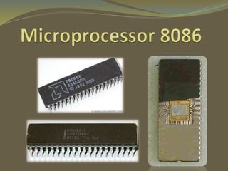
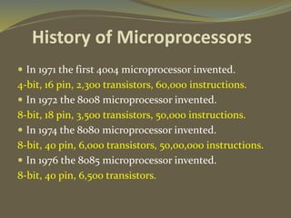
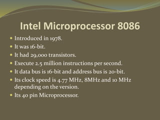
BY: Adeel Rasheed
 In 1971 the first 4004 microprocessor invented.
4-bit, 16 pin, 2,300 transistors, 60,000 instructions.
 In 1972 the 8008 microprocessor invented.
8-bit, 18 pin, 3,500 transistors, 50,000 instructions.
 In 1974 the 8080 microprocessor invented.
8-bit, 40 pin, 6,000 transistors, 50,00,000 instructions.
 In 1976 the 8085 microprocessor invented.
8-bit, 40 pin, 6,500 transistors.
History of Microprocessors
Intel Microprocessor 8086
 Introduced in 1978.
 It was 16-bit.
 It had 29,000 transistors.
 Execute 2.5 million instructions per second.
 It data bus is 16-bit and address bus is 20-bit.
 Its clock speed is 4.77 MHz, 8MHz and 10 MHz
depending on the version.
 Its 40 pin Microprocessor.
8086 Internal Architecture
 8086 CPU has two parts which operate at the same
time
 Bus Interface Unit
 Execution Unit
 CPU functions
1. Fetch
2. Decode
3. Execute
8086 CPU
Bus Interface
Unit (BIU)
Execution Unit
(EU)
Bus Interface Unit (BIU):
 The BIU has to interact with memory and input and
output devices in fetching the instructions and data
required by the EU
 Sends out addresses for memory locations
 Fetches Instructions from memory
 Reads/Writes data to memory
 Sends out addresses for I/O ports
 Reads/Writes data to Input/Output ports
Parts of BIU:
 Instruction byte queue
 Segment registers
 Instruction pointer (IP)
 Address Adder (∑)
 Address Bus
Instruction Byte Queue:
Therefore fetch and execution are taking place
concurrently in order to improve the performance of the
microprocessor
Instruction Pointer:
 A 16-bit register
 BIU uses IP and CS registers to generate the 20-bit
address of the instruction to be fetched from memory
Code Segment
 That part of memory from where BIU is currently
fetching instruction code bytes
Stack Segment
 A section of memory set aside to store addresses
and data while a subprogram executes
Data & Extra Segments
 Used for storing data values to be used in the
program
Execution Unit (EU):
 EU is responsible for executing the instructions of the
programs and to carry out the required processing
 Tells BIU (addresses) where to fetch instructions or
data
 Decodes & Executes instructions
Parts of EU:
 Control unit
 Instruction decoder
 ALU
 General registers
 Flag register
 Pointers
 Index registers
 Control unit is responsible for the co-ordination of
all other units of the processor
 ALU performs various arithmetic and logical
operations over the data
 Instruction Decoder translates the instructions
fetched from the memory into a series of actions that
are carried out by the EU
 General registers are used for temporary storage
and manipulation of data and instructions
 EU has 8 general purpose registers
 Can be individually used for storing 8-bit data
 AL register is also called Accumulator
 The valid register pairs are – AX, BX, CX, DX
Flags
Pointers and Index
 Stack Pointer (SP) is a 16-bit register pointing to
program stack
 Base Pointer (BP) is a 16-bit register pointing to data in
stack segment. BP register is usually used for based, based
indexed or register indirect addressing.
 Source Index (SI) is a 16-bit register. SI is used for
indexed, based indexed and register indirect addressing, as
well as a source data addresses in string manipulation
instructions.
 Destination Index (DI) is a 16-bit register. DI is used
for indexed, based indexed and register indirect
addressing, as well as a destination data addresses in string
manipulation instructions.
P
I
N
s
Working Principles
 (i) The BIU outputs the contents of the instruction pointer
register (IP) onto the address bus, causing the selected byte or
word to be read into the BIU.
 (ii) Register IP is incremented by 1 to prepare for the next
instruction fetch.
 (iii) Once inside the BIU, the instruction is passed to the queue.
 (iv) Assuming that the queue is initially empty, the EU
immediately draws this instruction from the queue and begins
execution.
 (v) While the EU is executing this instruction, the BIU proceeds
to fetch a new instruction. Depending on the execution time of
the first instruction, the BIU may fill the queue with several
new instructions before the EU is ready to draw its next
instruction.
Microprocessor 8086

Microprocessor 8086

  • 2.
  • 3.
     In 1971the first 4004 microprocessor invented. 4-bit, 16 pin, 2,300 transistors, 60,000 instructions.  In 1972 the 8008 microprocessor invented. 8-bit, 18 pin, 3,500 transistors, 50,000 instructions.  In 1974 the 8080 microprocessor invented. 8-bit, 40 pin, 6,000 transistors, 50,00,000 instructions.  In 1976 the 8085 microprocessor invented. 8-bit, 40 pin, 6,500 transistors. History of Microprocessors
  • 4.
    Intel Microprocessor 8086 Introduced in 1978.  It was 16-bit.  It had 29,000 transistors.  Execute 2.5 million instructions per second.  It data bus is 16-bit and address bus is 20-bit.  Its clock speed is 4.77 MHz, 8MHz and 10 MHz depending on the version.  Its 40 pin Microprocessor.
  • 5.
    8086 Internal Architecture 8086 CPU has two parts which operate at the same time  Bus Interface Unit  Execution Unit  CPU functions 1. Fetch 2. Decode 3. Execute 8086 CPU Bus Interface Unit (BIU) Execution Unit (EU)
  • 6.
    Bus Interface Unit(BIU):  The BIU has to interact with memory and input and output devices in fetching the instructions and data required by the EU  Sends out addresses for memory locations  Fetches Instructions from memory  Reads/Writes data to memory  Sends out addresses for I/O ports  Reads/Writes data to Input/Output ports
  • 7.
    Parts of BIU: Instruction byte queue  Segment registers  Instruction pointer (IP)  Address Adder (∑)  Address Bus
  • 8.
    Instruction Byte Queue: Thereforefetch and execution are taking place concurrently in order to improve the performance of the microprocessor Instruction Pointer:  A 16-bit register  BIU uses IP and CS registers to generate the 20-bit address of the instruction to be fetched from memory
  • 9.
    Code Segment  Thatpart of memory from where BIU is currently fetching instruction code bytes Stack Segment  A section of memory set aside to store addresses and data while a subprogram executes Data & Extra Segments  Used for storing data values to be used in the program
  • 10.
    Execution Unit (EU): EU is responsible for executing the instructions of the programs and to carry out the required processing  Tells BIU (addresses) where to fetch instructions or data  Decodes & Executes instructions
  • 11.
    Parts of EU: Control unit  Instruction decoder  ALU  General registers  Flag register  Pointers  Index registers
  • 12.
     Control unitis responsible for the co-ordination of all other units of the processor  ALU performs various arithmetic and logical operations over the data  Instruction Decoder translates the instructions fetched from the memory into a series of actions that are carried out by the EU  General registers are used for temporary storage and manipulation of data and instructions  EU has 8 general purpose registers  Can be individually used for storing 8-bit data  AL register is also called Accumulator
  • 13.
     The validregister pairs are – AX, BX, CX, DX
  • 14.
  • 15.
    Pointers and Index Stack Pointer (SP) is a 16-bit register pointing to program stack  Base Pointer (BP) is a 16-bit register pointing to data in stack segment. BP register is usually used for based, based indexed or register indirect addressing.  Source Index (SI) is a 16-bit register. SI is used for indexed, based indexed and register indirect addressing, as well as a source data addresses in string manipulation instructions.  Destination Index (DI) is a 16-bit register. DI is used for indexed, based indexed and register indirect addressing, as well as a destination data addresses in string manipulation instructions.
  • 16.
  • 17.
    Working Principles  (i)The BIU outputs the contents of the instruction pointer register (IP) onto the address bus, causing the selected byte or word to be read into the BIU.  (ii) Register IP is incremented by 1 to prepare for the next instruction fetch.  (iii) Once inside the BIU, the instruction is passed to the queue.  (iv) Assuming that the queue is initially empty, the EU immediately draws this instruction from the queue and begins execution.  (v) While the EU is executing this instruction, the BIU proceeds to fetch a new instruction. Depending on the execution time of the first instruction, the BIU may fill the queue with several new instructions before the EU is ready to draw its next instruction.