This document provides an introduction to microcontroller basics and working with Arduino. It covers:
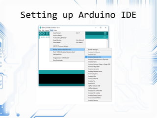
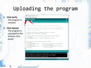
1. Downloading and setting up the Arduino IDE software.
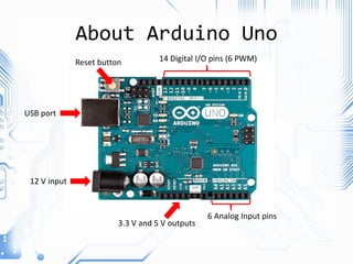
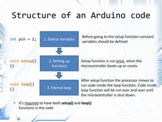
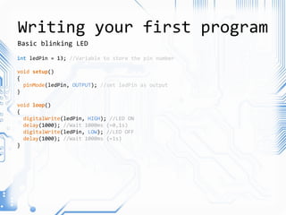
2. An overview of the Arduino Uno board's features and the basic structure of an Arduino code with setup() and loop() functions.
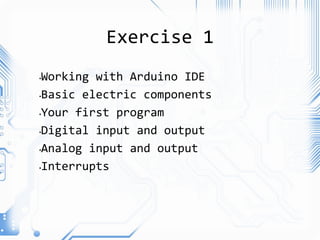
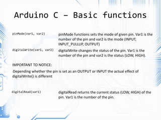
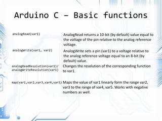
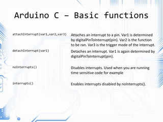
3. Examples of common Arduino functions for digital and analog input/output, interrupts, and PWM.
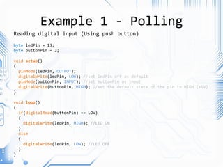
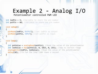
4. Two simple example codes - one using a push button and digital input, the other using a potentiometer and analog input to control an LED brightness.