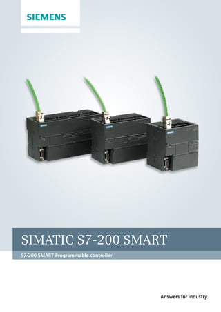
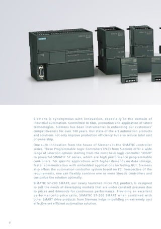
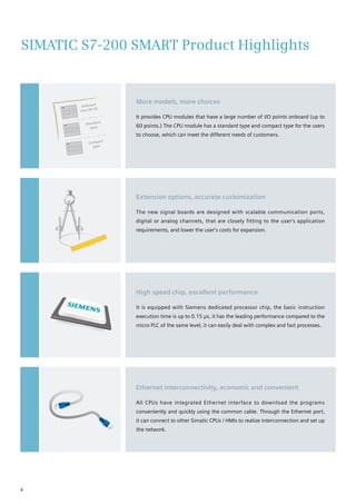
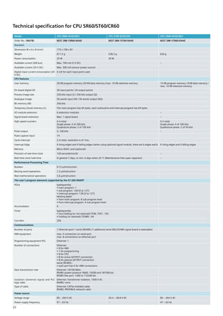
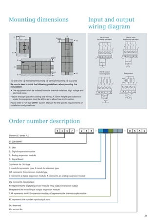
Siemens' SIMATIC S7-200 SMART PLC offers an affordable and flexible automation solution for developing markets. It provides a range of CPU modules with integrated I/O and communication ports. Additional I/O and communication can be added via cost-effective signal boards. The PLC uses a high-speed processor and user-friendly software to provide powerful motion control, networking, and programming capabilities despite its low cost. It can be integrated with other Siemens products to create complete automation solutions for applications like packaging machines.
Especialización Superior en PLC – Programable Logic Controller (Controlador Lógico Programable) es un dispositivo digital electrónico con una memoria programable para el almacenamiento de instrucciones, permitiendo la implementación de funciones específicas como ser: lógicas, secuenciales, temporizadas, de conteo y aritméticas; con el objeto de controlar máquinas y procesos.
Ingeniero Jorge Velazco Barranque
Contacto: 097436180
Ingeniería Electrónica:
www.facebook.com/groups/electronicauruguay
Equipo de tutores:
https://www.facebook.com/groups/tutoresenred
https://www.facebook.com/desarrollo.permanente
https://www.facebook.com/recursosabiertos
https://www.facebook.com/americaeduca
https://www.facebook.com/uruguayestudia
Siemens,
Catalog Thiết Bị Điện Siemens, Catalog Thiết Bị Điện,
Catalog Phụ Kiện Siemens, Catalog Phụ Kiện,
Catalog Siemens, Catalog,
http://dienhathe.com,
Chi tiết các sản phẩm khác của Siemens tại https://dienhathe.com
Xem thêm các Catalog khác của Siemens tại https://dienhathe.info
Để nhận báo giá sản phẩm Siemens vui lòng gọi: 0907.764.966
Siemens,
Catalog Thiết Bị Tự Động Siemens, Catalog Thiết Bị Tự Động
Catalog Phụ Kiện Siemens, Catalog Phụ Kiện,
Catalog Siemens, Catalog,
http://dienhathe.com,
Chi tiết các sản phẩm khác của Siemens tại https://dienhathe.com
Xem thêm các Catalog khác của Siemens tại https://dienhathe.info
Để nhận báo giá sản phẩm Siemens vui lòng gọi: 0907.764.966
Siemens,
Catalog Thiết Bị Điện Siemens, Catalog Thiết Bị Điện,
Catalog Phụ Kiện Siemens, Catalog Phụ Kiện,
Catalog Siemens, Catalog,
http://dienhathe.com,
Chi tiết các sản phẩm khác của Siemens tại https://dienhathe.com
Xem thêm các Catalog khác của Siemens tại https://dienhathe.info
Để nhận báo giá sản phẩm Siemens vui lòng gọi: 0907.764.966
Siemens,
Catalog Thiết Bị Tự Động Siemens, Catalog Thiết Bị Tự Động
Catalog Phụ Kiện Siemens, Catalog Phụ Kiện,
Catalog Siemens, Catalog,
http://dienhathe.com,
Chi tiết các sản phẩm khác của Siemens tại https://dienhathe.com
Xem thêm các Catalog khác của Siemens tại https://dienhathe.info
Để nhận báo giá sản phẩm Siemens vui lòng gọi: 0907.764.966
MIfa Systems is an Electronic Instrument & Equipment based private company, engaged in offering Digital Temperature Controller with advanced microcomputer including leading-edge sensor, therefore ensuring precise temperature calibrating and controlling operations. Driven by technical excellence,
http://www.mifasystems.com/
International Journal of Computational Engineering Research (IJCER) is dedicated to protecting personal information and will make every reasonable effort to handle collected information appropriately. All information collected, as well as related requests, will be handled as carefully and efficiently as possible in accordance with IJCER standards for integrity and objectivity.
At the market of electrical distribution, transport and generation networks, SELTA brings decades of experience and partnerships with major Italian and international operators. Solutions range from the systems for the control and management of low and medium voltage distribution substations, up to the automation systems of the high voltage transmission network. SELTA is also one of the top European leaders in Smart Grids.
SELTA offers a wide range of Automation/Smart Grid solutions for Energy/Transport electric networks: remote control and management of distribution substations; automation systems for HV/VHV transmission; Scada, RTU, protections; Distributed Automation, Dispersed Generation Management, Smart DMS for Voltage/Power regulation; service telecommunications; power line carrier systems.
www.envimart.vn - ĐT: 028 77727979 - sales@envimart.vn - Nền tảng cung cấp thiết bị, vật tư ngành nước và môi trường. Chuyên cung cấp vật tư cho dự án xử lý nước sạch, nước thải và môi trường. Envimart luôn đồng hành, tin cậy với đối tác nhà thầu, nhà tích hợp và người sử dụng.
STONE Tech is a manufacturer of HMI display module(Intelligent TFT LCD). We provide LCD modules/LCD Displays, Graphic LCM, smart Display LCD, TFT LCM, Custom LCD Module Display, and LCD panels. china LCD Manufacturers.
Beeteco.com là trang mua sắm trực tuyến thiết bị điện - Tự động hóa uy tín tại Việt Nam.
Chuyên cung cấp các thiết bị: Đèn báo nút nhấn, Relay, Timer, Contactor, MCCB ELCB, Biến tần, Van, Thiết bị cảm biến, phụ kiện tủ điện, .... Từ các thương hiệu hàng đầu trên thế giới.
www.beeteco.com @ Công ty TNHH TM KT ASTER
Số 7 Đại Lộ Độc Lập, KCN Sóng Thần 1, P. Dĩ An, Tx. Dĩ An, Bình Dương
www.facebook.com/beeteco
Tel: 0650 3617 012
Hotline: 0909.41.61.43
Quickly design infrared body temperature detectorVinsion Chan
Body temperature testing is necessary monitoring in our homes, in and out of the community or workplace, and during travel. Infrared body temperature detector helps reduce contact infection through non-contact temperature measurement. Here we come to talk to you about this system and the main design plan.
Cosmetic shop management system project report.pdfKamal Acharya
Buying new cosmetic products is difficult. It can even be scary for those who have sensitive skin and are prone to skin trouble. The information needed to alleviate this problem is on the back of each product, but it's thought to interpret those ingredient lists unless you have a background in chemistry.
Instead of buying and hoping for the best, we can use data science to help us predict which products may be good fits for us. It includes various function programs to do the above mentioned tasks.
Data file handling has been effectively used in the program.
The automated cosmetic shop management system should deal with the automation of general workflow and administration process of the shop. The main processes of the system focus on customer's request where the system is able to search the most appropriate products and deliver it to the customers. It should help the employees to quickly identify the list of cosmetic product that have reached the minimum quantity and also keep a track of expired date for each cosmetic product. It should help the employees to find the rack number in which the product is placed.It is also Faster and more efficient way.
CFD Simulation of By-pass Flow in a HRSG module by R&R Consult.pptxR&R Consult
CFD analysis is incredibly effective at solving mysteries and improving the performance of complex systems!
Here's a great example: At a large natural gas-fired power plant, where they use waste heat to generate steam and energy, they were puzzled that their boiler wasn't producing as much steam as expected.
R&R and Tetra Engineering Group Inc. were asked to solve the issue with reduced steam production.
An inspection had shown that a significant amount of hot flue gas was bypassing the boiler tubes, where the heat was supposed to be transferred.
R&R Consult conducted a CFD analysis, which revealed that 6.3% of the flue gas was bypassing the boiler tubes without transferring heat. The analysis also showed that the flue gas was instead being directed along the sides of the boiler and between the modules that were supposed to capture the heat. This was the cause of the reduced performance.
Based on our results, Tetra Engineering installed covering plates to reduce the bypass flow. This improved the boiler's performance and increased electricity production.
It is always satisfying when we can help solve complex challenges like this. Do your systems also need a check-up or optimization? Give us a call!
Work done in cooperation with James Malloy and David Moelling from Tetra Engineering.
More examples of our work https://www.r-r-consult.dk/en/cases-en/
About
Indigenized remote control interface card suitable for MAFI system CCR equipment. Compatible for IDM8000 CCR. Backplane mounted serial and TCP/Ethernet communication module for CCR remote access. IDM 8000 CCR remote control on serial and TCP protocol.
• Remote control: Parallel or serial interface.
• Compatible with MAFI CCR system.
• Compatible with IDM8000 CCR.
• Compatible with Backplane mount serial communication.
• Compatible with commercial and Defence aviation CCR system.
• Remote control system for accessing CCR and allied system over serial or TCP.
• Indigenized local Support/presence in India.
• Easy in configuration using DIP switches.
Technical Specifications
Indigenized remote control interface card suitable for MAFI system CCR equipment. Compatible for IDM8000 CCR. Backplane mounted serial and TCP/Ethernet communication module for CCR remote access. IDM 8000 CCR remote control on serial and TCP protocol.
Key Features
Indigenized remote control interface card suitable for MAFI system CCR equipment. Compatible for IDM8000 CCR. Backplane mounted serial and TCP/Ethernet communication module for CCR remote access. IDM 8000 CCR remote control on serial and TCP protocol.
• Remote control: Parallel or serial interface
• Compatible with MAFI CCR system
• Copatiable with IDM8000 CCR
• Compatible with Backplane mount serial communication.
• Compatible with commercial and Defence aviation CCR system.
• Remote control system for accessing CCR and allied system over serial or TCP.
• Indigenized local Support/presence in India.
Application
• Remote control: Parallel or serial interface.
• Compatible with MAFI CCR system.
• Compatible with IDM8000 CCR.
• Compatible with Backplane mount serial communication.
• Compatible with commercial and Defence aviation CCR system.
• Remote control system for accessing CCR and allied system over serial or TCP.
• Indigenized local Support/presence in India.
• Easy in configuration using DIP switches.
NO1 Uk best vashikaran specialist in delhi vashikaran baba near me online vas...Amil Baba Dawood bangali
Contact with Dawood Bhai Just call on +92322-6382012 and we'll help you. We'll solve all your problems within 12 to 24 hours and with 101% guarantee and with astrology systematic. If you want to take any personal or professional advice then also you can call us on +92322-6382012 , ONLINE LOVE PROBLEM & Other all types of Daily Life Problem's.Then CALL or WHATSAPP us on +92322-6382012 and Get all these problems solutions here by Amil Baba DAWOOD BANGALI
#vashikaranspecialist #astrologer #palmistry #amliyaat #taweez #manpasandshadi #horoscope #spiritual #lovelife #lovespell #marriagespell#aamilbabainpakistan #amilbabainkarachi #powerfullblackmagicspell #kalajadumantarspecialist #realamilbaba #AmilbabainPakistan #astrologerincanada #astrologerindubai #lovespellsmaster #kalajaduspecialist #lovespellsthatwork #aamilbabainlahore#blackmagicformarriage #aamilbaba #kalajadu #kalailam #taweez #wazifaexpert #jadumantar #vashikaranspecialist #astrologer #palmistry #amliyaat #taweez #manpasandshadi #horoscope #spiritual #lovelife #lovespell #marriagespell#aamilbabainpakistan #amilbabainkarachi #powerfullblackmagicspell #kalajadumantarspecialist #realamilbaba #AmilbabainPakistan #astrologerincanada #astrologerindubai #lovespellsmaster #kalajaduspecialist #lovespellsthatwork #aamilbabainlahore #blackmagicforlove #blackmagicformarriage #aamilbaba #kalajadu #kalailam #taweez #wazifaexpert #jadumantar #vashikaranspecialist #astrologer #palmistry #amliyaat #taweez #manpasandshadi #horoscope #spiritual #lovelife #lovespell #marriagespell#aamilbabainpakistan #amilbabainkarachi #powerfullblackmagicspell #kalajadumantarspecialist #realamilbaba #AmilbabainPakistan #astrologerincanada #astrologerindubai #lovespellsmaster #kalajaduspecialist #lovespellsthatwork #aamilbabainlahore #Amilbabainuk #amilbabainspain #amilbabaindubai #Amilbabainnorway #amilbabainkrachi #amilbabainlahore #amilbabaingujranwalan #amilbabainislamabad
TECHNICAL TRAINING MANUAL GENERAL FAMILIARIZATION COURSEDuvanRamosGarzon1
AIRCRAFT GENERAL
The Single Aisle is the most advanced family aircraft in service today, with fly-by-wire flight controls.
The A318, A319, A320 and A321 are twin-engine subsonic medium range aircraft.
The family offers a choice of engines
Courier management system project report.pdfKamal Acharya
It is now-a-days very important for the people to send or receive articles like imported furniture, electronic items, gifts, business goods and the like. People depend vastly on different transport systems which mostly use the manual way of receiving and delivering the articles. There is no way to track the articles till they are received and there is no way to let the customer know what happened in transit, once he booked some articles. In such a situation, we need a system which completely computerizes the cargo activities including time to time tracking of the articles sent. This need is fulfilled by Courier Management System software which is online software for the cargo management people that enables them to receive the goods from a source and send them to a required destination and track their status from time to time.
Saudi Arabia stands as a titan in the global energy landscape, renowned for its abundant oil and gas resources. It's the largest exporter of petroleum and holds some of the world's most significant reserves. Let's delve into the top 10 oil and gas projects shaping Saudi Arabia's energy future in 2024.
Quality defects in TMT Bars, Possible causes and Potential Solutions.PrashantGoswami42
Maintaining high-quality standards in the production of TMT bars is crucial for ensuring structural integrity in construction. Addressing common defects through careful monitoring, standardized processes, and advanced technology can significantly improve the quality of TMT bars. Continuous training and adherence to quality control measures will also play a pivotal role in minimizing these defects.
Overview of the fundamental roles in Hydropower generation and the components involved in wider Electrical Engineering.
This paper presents the design and construction of hydroelectric dams from the hydrologist’s survey of the valley before construction, all aspects and involved disciplines, fluid dynamics, structural engineering, generation and mains frequency regulation to the very transmission of power through the network in the United Kingdom.
Author: Robbie Edward Sayers
Collaborators and co editors: Charlie Sims and Connor Healey.
(C) 2024 Robbie E. Sayers
2. Siemens is synonymous with innovation, especially in the domain of
industrial automation. Committed to R&D, promotion and application of latest
technologies, Siemens has been instrumental in enhancing our customers’
competitiveness for over 140 years. Our state-of-the art automation products
and solutions not only improve production efficiency but also reduce total cost
of ownership.
One such innovation from the house of Siemens is the SIMATIC controller
series. These Programmable Logic Controllers (PLC) from Siemens offer a wide
range of selection options starting from the most basic logic controller ‘LOGO!’
to powerful SIMATIC S7 series, which are high performance programmable
controllers. For specific applications with higher demands on data storage,
faster communication with embedded applications including GUI, Siemens
also offers the automation controller system based on PC. Irrespective of the
requirements, one can flexibly combine one or more Simatic controllers and
customize the solution optimally.
SIMATIC S7-200 SMART, our newly launched micro PLC product, is designed
to suit the needs of developing markets that are under constant pressure due
to prices and demands for continuous performance. Providing an excellent
performance-to-price ratio, SIMATIC S7-200 SMART when combined with
other SMART drive products from Siemens helps in building an extremely cost
effective yet efficient automation solution.
2
3. Technical specification for analogue input module................. 26
Technical specification for analogue output module.............. 26
Technical specification for analogue input/output module...... 26
Technical specification for digital input/output signal board... 27
Technical specification for analogue output signal board....... 27
Technical specification for battery signal board ..................... 27
Technical specification for RS485/232 signal board................ 27
Technical specification for RTD module.................................. 28
Technical specification for thermocouple module.................. 28
General technical specification.............................................. 28
Mounting dimensions .......................................................... 29
Input and output wiring diagram........................................... 29
Order number description..................................................... 29
Schematic diagram of the module and the signal board
wiring .................................................................................. 30
Order data............................................................................ 35
Product highlights ................................................................ 04
CPU module.......................................................................... 06
Signal board.......................................................................... 08
Network communications..................................................... 09
Motion control...................................................................... 10
User-friendly software improves programming efficiency....... 12
SMART micro automation solutions....................................... 14
Common SD card – Fast Update............................................. 15
Technical specification.......................................................... 16
Technical specification for CPU SR20/ST20............................. 16
Technical specification for CPU SR30/ST30 ............................ 18
Technical specification CPU SR40/ST40/CR40 ......................... 20
Technical specification CPU SR60/ST60/CR60 ......................... 22
Technical specification for digital input module..................... 24
Technical specification for digital output module................... 24
Technical specification for digital input/output module.......... 25
Contents
3
4. SIMATIC S7-200 SMART Product Highlights
More models, more choices
It provides CPU modules that have a large number of I/O points onboard (up to
60 points.) The CPU module has a standard type and compact type for the users
to choose, which can meet the different needs of customers.
Extension options, accurate customization
The new signal boards are designed with scalable communication ports,
digital or analog channels, that are closely fitting to the user's application
requirements, and lower the user’s costs for expansion.
High speed chip, excellent performance
It is equipped with Siemens dedicated processor chip, the basic instruction
execution time is up to 0.15 μs, it has the leading performance compared to the
micro PLC of the same level, it can easily deal with complex and fast processes.
Ethernet interconnectivity, economic and convenient
All CPUs have integrated Ethernet interface to download the programs
conveniently and quickly using the common cable. Through the Ethernet port,
it can connect to other Simatic CPUs / HMIs to realize interconnection and set up
the network.
Onboard
max 60 I/O
Standard
type
Compact
type
4
5. Tri-axial pulse, freedom in motion
Provides powerful functions of speed and positioning control, the CPU module
can maximally integrate three 100 kHz high speed pulse outputs, and support
PWM/PTO.
Common SD card, fast update
This PLC integrates Micro SD card slot, supports common Micro SD card, can
be used to update the program or device firmware, and can provide great
convenience to the engineer who conducts the field service.
User-friendly software, programming efficiency
Based on the powerful functions inherited from the Siemens programming
software, it has absorbed more humanized design which has enhanced the user
friendliness of the software greatly. Improved the efficiency in developing the
program.
Perfect integration, seamless integration
The perfect integration of SIMATIC S7-200 SMART, Basic LINE HMI and SINAMICS
V20/V90, forms the micro automation solutions that is cost-effective; meeting the
OEM customer’s full range of demand.
5
6. Ethernet interface
I/O expansion module
RS485 serial port
Signal board expansion
Supporting Micro SD card
Real-time clock 1)
High speed counters
High speed pulse output2)
1)
Only supports the standard type CPU module
2)
Only supports the standard type transistor output;
CPU module
The new S7-200 SMART has two different types of CPU modules, i.e. standard type and compact type.
Standard type CPU is expandable with I/O expansion modules and signal boards. Compact type CPUs
are non expandable with I/O expansion modules and signal boards.
Type CR40 CR60 SR20 SR30 SR40 SR60 ST20 ST30 ST40 ST60
High speed counter
4 at 100 kHz for
single phase
4 at 200 kHz for single phase
High speed pulse
output
—
2 at
100 kHz
3 at 100 kHz
Number of
communication
ports
2 2 ~ 3
Number of
Expansion modules
— 6
Maximum I/O
handling capacity 3) 40 60 212 222 232 252 212 222 232 252
Maximum
analogue I/O3) — 36
3)
The maximum I/O handling capacity is considering I/O expansion with Signal boards.
Compact type
CPU module
CPU CR40/CR60
Standard type CPU module
CPU SR20/SR30/SR40/SR60
CPU ST20/ST30/ST40/ST60
6
7. Communication and running state
indicator, the PLC state can be seen easily.
The input and output
terminals of all modules
are removable.
Generic Micro SD card supports
program downloading and PLC
firmware updating
Siemens dedicated high
speed chip is incorporated,
with basic instruction
execution time up to 0.15 μs;
It is equipped with super
capacitor, when the power is
down, it still can guarantee
the normal work of the clock
Signalboardextensionachieves
accurateconfiguration,without
occupyingspaceintheelectric
controlcabinet.
Integrated Ethernet
port that makes the
downloading and
networking equipment
more convenient;
Convenient installation,
support rail type and
screw type installation
Pin plug connection,
module can be connected
more closely
7
8. Installation steps
Remove the cover board of terminal Remove the cover board with Screw
driver
No fastening screw is required,
gently insert it;
The installation is complete
Signal board
Signal board configuration
When the standard CPU module is selected in the system block, the aforementioned
four signal boards will display the SB options:
• When SB DT04 is selected, the system can automatically distribute I7.0 and Q7.0 as the
beginning of the I/O image area
• When SB AQ01 is selected, the system can automatically allocates AQW12 as the I/O
image area
• When SB CM01is selected, it can be done via selecting the RS232 or RS485 in the port
type setting box.
• When SB BA01 is selected, the low power consumption alarm can be initialized or the
power consumption state can be monitored via I7.0.
Model Specification Description
SB DT04 2DI/2DO
transistor output
It provides additional digital I/O extensions, and support
2 digital inputs and 2 digital transistor outputs.
SB AQ01 1AO It provides additional analogue I/O extension, and
support 1 analogue output, with a precision 12 bits.
SB CM01 RS232/RS485 It provides additional RS232 or RS485 serial
communication interface, the conversion can be
realized via simple configuration in the software.
SB BA01 Battery module It supports the generic CR1025 cell (battery), which can
drive the clock for about 1 year.
Basic information of the signal board
The signal board is mounted directly on the front of the CPU body; without occupying the cabinet space,
its installation and disassembly are convenient and quick. For a small amount of I/O points extension and
more demand for communication ports, the signal board with new design can provide more economical and
flexible solutions.
8
9. All S7-200 SMART CPUs offer 1x Ethernet interface and the 1x RS485
interface onboard. Using Signal board CM01, one can add additional
RS485/232 interface.
Ethernet communication
All the CPU modules are equipped with Ethernet interface, which supports Siemens S7
protocol, can support many terminal connections:
• Can be used as the programs downloading port (via general network cable)
• Communicate with Simatic Key/touch HMI with Profinet/Ethernet interface, maximally
support 8 sets of equipment
• Communicate with multiple Ethernet equipment through the switch to achieve fast data
communication.
• Supports up to 8 active GET/PUT connections and 8 passive GET/PUT connections.
Serial communication
On board RS485 port as well as additional RS232/485 port using CM01 can communicate
with the inverter and touch screen and so on third party equipments. Signal board offers
configurable RS232/RS485 port, maximally supports for up to 4 devices.
Serial port supports the following protocols:
• Modbus RTU
• PPI
• USS
• Free port communication (for interconnection with Bar code scanners, weighing
scales, serial printers etc.)
Communication with the host computer*
Using Siemens PC Access tool, it is possible to read the data from S7-200 SMART on to
the host computer. This can be used for simple GUI requirements for data monitoring or
data archiving.
(PC Access is an OPC server protocol specifically developed for S7-200 series PLC, an
OPC software dedicatedly developed for interaction between the micro PLC and host
computer)
Network communication
PC Access
HMI
HMI
2# PLC
PLC
PLC
1# PLC
1 # servo
drive
2 # servo
drive
3 # servo
drive
1 # motor 2 # motor 3 # motor
Switch
*) it will be released soon, please consult the Siemens offices and authorized distributors for the specific information.
9
10. Motion control
Basic functions of motion control
• Standard type transistor output module CPU, ST30/ST40/ST60 provides
three 100 kHz high speed pulse output (ST20 provides two 100 kHz),
supports PWM (pulse width modulation) and PTO (pulse train output).
• In PWM mode, the cycle of the output pulse is fixed, the pulse width
and duty cycle are adjusted by the program, which can adjust the
speed of the motor, the opening of valves etc.
• In PTO mode (motion control), the output pulse can be configured
as multiple modes of operation, including automatically finding the
original point, for realising the control of the stepper motor or servo
motor, achieving the purpose of speed adjustment and positioning;
• The Q0.0, Q0.1 and Q0.3 on the CPU body can be configured as the
PWM output or high speed pulse output, the above functions can be
set up via the Wizard;
PWM and motion control wizard settings
In order to simplify the control functions in your application, the
position control wizard provided by the STEP 7- Micro/WIN SMART
can help you complete the PWM and the PTO configuration in a few
minutes. The wizard can generate the position instructions, you can
dynamically control the speed and position in your application with
these instructions.
According to the user selected PWM pulse number, the PWM wizard
can generate PWMx_RUN subroutine frame corresponding to editing.
Motion control wizards can maximally provide the settings for three
pulse outputs, the pulse output speed is adjustable from 20 Hz to
100 kHz.
PLC
1# servo drive 2# servo drive 3# servo drive
1 # motor 2 # motor 3# motor
S7-200 SMART CPU provides maximum three 100KHz high speed pulse outputs, it can be configured for PWM output or
motion control output through the powerful and flexible setup wizard, providing a unified solution for speed and position
control of both the stepper motor or servo motor, satisfying the precise positioning requirements of the small mechanical
equipment.
10
11. Monitoring of motion control
In order to help users develop motion control scheme, STEP
7- Micro/WIN SMART provides the motion control panel. The
operation, configuration and envelope configuration settings
let the users easily monitor, on the motion control function
operation, the start and test phases in the development process.
• The use of the motion control panel can verify whether the
motion control wiring is correct or not, you can adjust the
configuration data and test each mobile envelope;
• Display the current speed, current position and direction of the
bit control, as well as the input and output of LED (except pulse
LED) status;
• View to modify the configuration settings of the bit control
operation stored in the CPU module
Motion control features
• It provides configurable measurement system, it can use the
engineering units (such as inches or centimetres) when inputting the
data, and can also use the pulse number.
• it provides configurable backlash compensation;
• it supports the absolute, relative and manual control modes;
• it supports the continuous operation;
• it provides up to 32 groups of motion envelope, each envelope can set
maximally 16 levels of speed;
• it provides 4 different reference point searching modes, each mode can
select the initial direction search and the final approach direction.
Absolute position
0 ending
Starting position
Single speed continuous
rotation
Controlled by the program, until
another command is sent (such
as “terminating commands”
With stop trigger Single speed
continuous rotation
On reaching RPS signal
Target speed stops
Relative position
Stating ending position
measured from
the starting point
Double Speed continuous
rotation the target speed when
RPS is not activated
the target speed when
RPS is activated
Typical applications
Labelling machine Pillow-type packaging machine Woodworking machinery
Label
feeding
Label
Sticking
Stock
feeding
Film
feeding
X-axis
Z-axis
Y-axis
Horizontal
cutting
11
12. STEP 7- Micro/WIN SMART is the programming software of the S7-200 SMART, it can run smoothly on the Windows XP
SP3/Windows 7 Operating System. It supports LAD (ladder diagram), STL (Statement List), FBD (function block diagram)
programming languages, freely converting between parts of language, the installation file is less than 100 MB. While
inheriting the excellent programming idea of the STEP 7- Micro/WIN, the more user-friendly design makes programming
easier and project development more efficient.
User-friendly software improves programming
efficiency
New menu design
It has no more traditional drop-down menu. It has adopted the band-type
menu design, all menu options can be seen completely. The image of the
icon display makes the operation more convenient.
By double clicking on the menu, it can be hidden so as to provide more
space for a visual programming window.
Fully movable window design
All windows in the software interface can move freely, and provide eight
kinds of drag and drop methods.
The main window, the program editor, the output window, variable table,
state diagram etc. windows can be combined according to the user's
habits, maximally improve the programming efficiency.
The definitions of variables and program notes
The users can define the variable name according to the process flow, and
can call through the variable name directly, allowing users to fully enjoy
the convenience of high-level programming language. A special function
registers the address call, automatically naming the variable, which can
now be called directly the next time.
Micro/WIN SMART provides a perfect function for annotation, can add
annotations to program block, programming network and variables,
with its readability greatly improved. When the mouse is moved to the
instruction block, data types supported by each pin are automatically
displayed.
12
13. STEP 7-Micro/WIN SMART Software features:
1. New menu design 2. Fully movable window design
3. Variable definitions and notes 4. Novel wizard setting
5. Status monitoring 6. Convenient command Library
7. Powerful password protection functions ……….
For detailed information about the software, consult the S7-200 SMART System
Manual.
Convenient command Library
In PLC programming, the same tasks that are repetitively executed will be generally included in a
subprogram, which can be directly used in the future. The use of subroutines can better organize
the program structure, facilitate the debugging and reading.
Micro/WIN SMART provides the command library functions, converting the subroutine into a block
of instructions, as a common block of instructions, which will be directly dragged and dropped into
the programming interface to complete the call. The command library function provides password
protection function, preventing the database files from being randomly reviewed or modified.
In addition, Siemens offers a large instruction library to complete a variety of functions, which can
be easily added into the software.
Setup wizard
Micro/WIN SMART integrates simple and quick wizard settings; you can just follow the wizard
prompts to set up the parameters for each step of the complex function setting. The new guidance
function allows the user to directly set up a step function, and without the need to reset every step,
to modify the wizard settings.
The wizard setting supports the following functions:
• HSC (high speed counter)
• Motion control
• PID
• PWM (Pulse width Modulation)
• Text display
Status monitoring
In the Micro/WIN SMART status graph, it can monitor the current values of each input / output
channel of PLC, at the same time, it can conduct the mandatory input operation to test the program
logic for each channel.
Status monitoring value can be displayed in numerical form, and can also be directly displayed in
the waveform, the aforementioned two can also be switched each other.
In addition, the Micro/WIN SMART system can monitor the PID and motion control operation,
equipment operation status through the dedicate operation panel.
13
14. SIMATIC Touch/Key HMI
Ethernet
SIMATIC S7-200 SMART SINAMICS V20
USS / MODBUS RTU
SINAMICS V90
SIMOTICS S-1FL6
SIMOTICS GP 1LE0
SMART micro automation solutions
The perfect combination of Siemens SIMATIC micro-automation products and SINAMICS drive products has created new micro
automation solutions that are economical, reliable and easy to use. SIMATIC S7-200 SMART PLC, SIMATIC BASIC LINE touch/
Key HMI, SINAMICS V20 inverter and SINAMICS V90 servo system, that are of high performance-to-price ratio helps users to
improve the performance of machinery and equipment, reduce the development cost, significantly shorten the launching
time of the machine and equipment, and effectively improve the market competitiveness of the user.
Recommendations for the use of S7-200 SMART:
• While programming and debugging, it is suggested to, using 1 set of ordinary switchboard, to connect the related equipment (including PLC, touch
screen, computer) to the switch. After downloading the PLC or touch screen programs, they can be directly tested on the touch screen through
touch. When testing the PLC working state, there is no need to use a cable to connect the PLC and touch screen.
• Through the use of Micro SD card the fast and batch downloading of the PLC program can be realized. The well-prepared source card can be
delivered to the end user by courier, or, in the scenario of urgent demand, the source file stored in the card can be sent via Email directly to the user
at the site, the source file will be copied to the SD card and can be used after receiving.
14
15. Common SD card – Fast Update!!
Restore factory settings
A memory card can be used to erase all retained data, putting the CPU
back into a factory default condition.
Program Transfer
A memory card can be used to transfer user program content into the
CPU's permanent memory, completely or partially replacing content
already in the load memory.
For duplication of program from one CPU to other CPUs, you need not
require software. Time & cost saving is also achieved.
Firmware upgrade
A memory card can be used to update the firmware in a CPU and any
connected expansion modules.
No return to the factory for FW upgrade, it can be done with SD card.
The S7-200 SMART CPUs support the use of a microSDHC card for:
• User program transfer.
• Reset CPU to factory default condition.
• Firmware update of the CPU and attached expansion modules as supported
You can use any standard, commercial microSDHC card with a capacity in the range 4GB to 16GB.For detailed information about the
software, consult the S7-200 SMART System Manual.
15
16. Technical specifications
Technical specification for CPU SR20/ST20
Model CPU SR20 AC/DC/RLY CPU ST20 DC/DC/DC
Order No.: (MLFB) 6ES7 288-1SR20-0AA0 6ES7 288-1ST20-0AA0
Standard
Dimension W x H x D (mm) 90 x 100 x 81
Weight 367.3 g 320 g
Power consumption 14 W 20W
Available current (EM bus) Max. 740 mA (5 V DC) Max. 1110 mA (5 V DC)
Available current (24 V DC) Max. 300 mA (sensor power source)
Digital input current consumption (24 V DC) 4mA for each input point used
CPU features
User memory 12 KB program memory /8 KB data memory /max. 10 KB retentive memory
On board digital I/O 12 input points / 8 output points
Process image size 256 bits input (I) / 256 bits output (Q)
Analog image 56 words input (AI) / 56 words output (AQ)
Bit memory (M) 256 bits
Temporary (local) memory The main program has 64 bytes, each subroutine and interrupt program has 64 bytes
I/O module extension 6 extension modules
Signal board extension Max. 1 signal board
High speed counters 4 in total
Single phase: 4 of 200 kHz
Quadrature phase: 2 of 100 kHz
Pulse output – 2 of 100 kHz
Pulse capture input 12
Cycle interrupt 2 in total, resolution is of 1ms,
Interrupt Edge 4 rising edges and 4 falling edges (when using optional signal board, there are 6 edges each)
Memory Micro SDHC card (optional)
Precision of real-time clock 120 seconds/month
Real-time clock hold time In general 7 days, or min. 6 days when 25 °C (Maintenance free super capacitor)
Performance/ Processing Time
Boolean 0.15 μs/instruction
Moving word operations 1.2 μs/instruction
Real mathematical operations 3.6 μs/instruction
The user’s program elements supported by the S7-200 SMART
POUs type/quantity
• main program: 1
• sub-program: 128 (0 to 127)
• interrupt program: 128 (0 to 127)
Nesting depth
• from main program: 8 sub-program level
• from interrupt program: 4 sub-program level
Accumulators 4
Timer type/quantity
• non-holding (or not retained) (TON, TOF) : 192
• holding (or retained) (TONR) : 64
Counters 256
Communications
Number of ports 1 Ethernet port/ 1 serial (RS485) /1 additional serial (optional RS232/485 signal board) port
HMI equipment max. 4 connection on serial port
max. 8 connections on ethernet port
Programming equipment (PG) Ethernet: 1
Number of connections Ethernet:
• 8 for HMI
• 1 for programming
• 8 for CPU
• 8 for active GET/PUT connection
• 8 for passive GET/PUT connection
serial (RS485) :
• each port has 4 for HMI connections
Data transmission rate Ethernet: 10/100 Mb/s
RS485 system protocol: 9600, 19200 and 187500 b/s
RS485 free port: 1200 to 115200 b/s
Isolation (external signal and PLC logic side) Ethernet: Transformer isolation, 1500 V AC
RS485: none
Type of cable Ethernet: CAT5e shielded cable
RS485: PROFIBUS network cable
Power source
Voltage range 85 ~ 264 V AC 20.4 ~ 28.8 V DC
Power supply frequency 47 ~ 63 Hz –
16
17. Model (continued) CPU SR20 AC/DC/RLY CPU ST20 DC/DC/DC
Input current When the maximum load is reached, only CPU is included
210 mA when voltage is 120 V AC (with a 300 mA sensor power output)
90 mA when voltage is 120 V AC (without a 300 mA sensor power output)
120 mA when voltage is 240 V AC (with a 300 mA sensor power output)
60 mA when voltage is 240 V AC (without a 300 mA sensor power output)
When the max load is reached, it CPU and all the scalable extensions are included
290 mA when voltage is 120 V AC
170 mA when voltage is 240 V AC
When the maximum load is reached, only CPU is included
160 mA when voltage is 24 V DC (without a 300 mA
sensor power output)
430 mA when voltage is 24 V DC (with a 300 mA sensor
power output)
When the max load is reached, CPU and all the scalable
extensions are included
720 mA when voltage is 24 V DC
Inrush current (max) 9.3 A when voltage is 264 V AC 11.7 A when voltage is 28.8 DC
Isolation (input power with the logic side) 1500 V AC –
Leakage current, AC line for functional earthing Max 0. 5 mA –
Hold time (power off) 30 ms when voltage is 120 V AC
200 ms when voltage is 240 V AC
20 ms when voltage is 24 V DC
Internal fuse (cannot be replaced by the user) 3 A, 250 V, Slow-blow fuse 3 A, 250 V, Slow-blow fuse
Sensor power source
Voltage range 20.4 ~ 28.8 V DC
Rated output current (max) 300 mA (short circuit protection)
Maximum ripple noise (<10 MHz) <1 V peak-peak value
Isolation (CPU logic side and sensor power source) Not isolated
Digital input
Number of input points 12
Type The sinking / sourcing type (IEC type 1 sinking) The sinking/sourcing type (IEC type 1 sinking excluding
I0.0 to I0.3)
Rated voltage It is 24V DC when the current is 4 mA, nominal value
Allowable continuous voltage Max 30 V DC
Surge voltage 35 V DC, lasting 0.5 s
Logic 1 signal (min) It is 15 V DC when the current is 2.5 mA The voltage is 4 V DC when it ranges from I0.0 to I0.3,
I0.6 to I0.7: 8 mA
Other input: 15 V DC when it is 2.5 mA
Logic 0 signal (min) It is 5 V DC when the current is 1 mA The voltage is 1 V DC when it ranges from I0.0 to I0.3,
I0.6 to I0.7: 1 mA
Other input: 5 V DC when it is 1 mA.
Isolation (field side and logic side) 500 V AC, lasting 1 min
Isolation group 1
Filter time Each channel can be separately selected (point I0.0 to 11.3) :
0.2, 0.4, 0.8, 1.6, 3.2, 6.4 and 12.8 µs
0.2, 0.4, 0.8, 1.6, 3.2, 6.4 and 12.8 ms
HSC clock input frequency (max)
(Logic 1 battery = 15 ~ 26 V DC)
Single phase: 4 of 200 kHz
Quadrature phase: 2 of 100 kHz
Number of inputs that connect at the same time 12
Cable length (max), its unit is meter Shielded: 500m (normal input), 50m (HSC input) ;
non shielded: 300m (normal input)
I0.0 to I0.3, shielded (only limited to this category) :
500 m (normal input), 50 m (HSC input)
I0.6 to I0.7, shielded (only limited to this category) :
500 m (normal input),
All other inputs: shielded: 500 m (normal input) ;
non shielded: 300 m (normal input)
Digital output
Number of output 8
Type Relay, dry contact Solid state-MOSFET (source-type)
Voltage range 5 ~ 30 V DC or 5 ~ 250 V AC 20.4 ~ 28.8 V DC
Logic 1 signal when the current is max. – Min. 20 V DC
Logic 0 signal when the load is KG – Max. 0.1 V DC
Rated current at each point (max) 2.0 A 0.5 A
Rated current at each public end (max) 10.0 A 6 A
Lamp load 30 W DC/200 W AC 5 W
On state resistance New equipment is 0.2 Ω maximally Max. 0.6 Ω
Leakage current at each point – Max. 10 µ A
Surge current It is 7A when the contact is closed 8 A, max. lasting 100 ms
Overload protection none
Isolation (field side and logic side) 1500 V AC, lasting 1 min (coil and contact) none, (coil and logic side) 500 V AC, lasting 1 min
Isolation resistance New equipment is 100 MΩ minimally –
Disconnect the insulation between the contacts 750 V AC, lasting 1 min –
Isolated group 1 2
Inductive voltage clamp Not recommended L+ - 48 V DC, 1 W loss
Relay max. on/off frequency Not recommended
Switching delay (Qa.0-Qa.3) Max. 10 ms From the disconnection to connection max.1 µs
from the connection to disconnection is 3 µs max.
Switching delay (Qa.0-Qa.7) Max. 10 ms From the disconnection to connection max. 50 µs
from the connection to disconnection is 200 µs max.
Mechanical life (no load) 10,000,000 break/close cycles –
Contact life under the rated load 100,000 break/close cycles –
Output state under the STOP mode Last value or replicable value (The default value is 0)
Number of output that are connected at the same
time
8
Cable length Shielded: 500 m; non shielded: 300 m
17
18. Technical specification for CPU SR30/ST30
Model CPU SR30 AC/DC/RLY CPU ST30 DC/DC/DC
Order No.: (MLFB) 6ES7 288-1SR30-0AA0 6ES7 288-1ST30-0AA0
Standard
Dimension W x H x D (mm) 110 x 100 x 81
Weight 435 g 375 g
Power consumption 14 W 12W
Available current (EM bus) Max. 740 mA (5 V DC)
Available current (24 V DC) Max. 300 mA (sensor power source)
Digital input current consumption (24 V DC) 4mA for each input point used
CPU features
User memory 18 KB program memory /12 KB data memory /max. 10 KB retentive memory
On board digital I/O 18 input points / 12 output points
Process image size 256 bits input (I) / 256 bits output (Q)
Analog image 56 words input (AI) / 56 words output (AQ)
Bit memory (M) 256 bits
Temporary (local) memory The main program has 64 bytes, each subroutine and interrupt program has 64 bytes
I/O module extension 6
Signal board extension Max. 1 signal board
High speed counters 4 in total
Single phase: 4 of 200 kHz
Quadrature phase: 2 of 100 kHz
Pulse output – 3 of 100 kHz
Pulse capture input 12
Cycle interrupt 2 in total, resolution is of 1ms,
Interrupt Edge 4 rising edges and 4 falling edges (when using optional signal board, there are 6 edges each)
Memory Micro SDHC card (optional)
Precision of real-time clock 120 seconds/month
Real-time clock hold time In general 7 days, or min. 6 days when 25 °C (Maintenance free super capacitor)
Performance/ Processing Time
Boolean 0.15 μs/instruction
Moving word operations 1.2 μs/instruction
Real mathematical operations 3.6 μs/instruction
The user’s program elements supported by the S7-200 SMART
POUs type/quantity
• main program: 1
• sub-program: 128 (0 to 127)
• interrupt program: 128 (0 to 127)
Nesting depth
• from main program: 8 sub-program level
• from interrupt program: 4 sub-program level
Accumulators 4
Timer type/quantity
• non-holding (or not retained) (TON, TOF) : 192
• holding (or retained) (TONR) : 64
Counters 256
Communications
Number of ports 1 Ethernet port/ 1 serial (RS485) /1 additional serial (optional RS232/485 signal board) port
HMI equipment max. 4 connection on serial port
max. 8 connections on ethernet port
Programming equipment (PG) Ethernet: 1
Number of connections Ethernet:
• 8 for HMI
• 1 for programming
• 8 for CPU
• 8 for active GET/PUT connection
• 8 for passive GET/PUT connection
serial (RS485) :
• each port has 4 for HMI connections
Data transmission rate Ethernet: 10/100 Mb/s
RS485 system protocol: 9600, 19200 and 187500 b/s
RS485 free port: 1200 to 115200 b/s
Isolation (external signal and PLC logic side) Ethernet: Transformer isolation, 1500 V AC
RS485: none
Type of cable Ethernet: CAT5e shielded cable
RS485: PROFIBUS network cable
Power source
Voltage range 85 ~ 264 V AC 20.4 ~ 28.8 V DC
Power supply frequency 47 ~ 63 Hz –
18
19. Model CPU SR30 AC/DC/RLY CPU ST30 DC/DC/DC
Input current When the maximum load is reached, only CPU is included
92 mA (including power source of the sensor) when the voltage is 120 V AC
40 mA (excluding power source of the sensor) when the voltage is 120 V AC
52 mA (including power source of the sensor) when the voltage is 240 V AC
27 mA (excluding power source of the sensor) when the voltage is 240 V AC
When the max load is reached, it CPU and all the scalable extensions are included
136 mA when voltage is 120 V AC
72 mA when voltage is 240 V AC
When the maximum load is reached, only CPU is included
64 mA when voltage is 24 V DC (without a 300 mA
sensor power output)
365 mA when voltage is 24 V DC (with a 300 mA sensor
power output)
When the max load is reached, CPU and all the scalable
extensions are included
624 mA when voltage is 24 V DC
Inrush current (max) 8.9 A when voltage is 264 V AC 6 A when voltage is 28.8 V DC
Isolation (input power with the logic side) 1500 V AC –
Leakage current, AC line for functional earthing Max 0. 5 mA –
Hold time (power off) 30 ms when voltage is 120 V AC
200 ms when voltage is 240 V AC
20 ms when voltage is 24 V DC
Internal fuse (cannot be replaced by the user) 3 A, 250 V, Slow-blow fuse
Sensor power source
Voltage range 20.4 ~ 28.8 V DC
Rated output current (max) 300 mA (short circuit protection)
Maximum ripple noise (<10 MHz) <1 V peak-peak value
Isolation (CPU logic side and sensor power source) Not isolated
Digital input
Number of input points 18
Type The sinking / sourcing type (IEC type 1 sinking) The sinking/sourcing type (IEC type 1 sinking excluding
I0.0 to I0.3)
Rated voltage It is 24 V DC when the current is 4 mA, rated value
Allowable continuous voltage Max 30 V DC
Surge voltage 35 V DC, lasting 0.5 s
Logic 1 signal (min) It is 15 V DC when the current is 2.5 mA The voltage is 4 V DC when it ranges from I0.0 to I0.3,
I0.6 to I0.7: 8 mA
Other input: 15 V DC when it is 2.5 mA
Logic 0 signal (min) It is 5 V DC when the current is 1 mA The voltage is 1 V DC when it ranges from I0.0 to I0.3,
I0.6 to I0.7: 1 mA
Other input: 5 V DC when it is 1 mA.
Isolation (field side and logic side) 500 V AC, lasting 1 min
Isolation group 1
Filter time Each channel can be separately selected (point I0.0 to I1.5) :
0.2, 0.4, 0.8, 1.6, 3.2, 6.4 and 12.8 µs
0.2, 0.4, 0.8, 1.6, 3.2, 6.4 and 12.8 ms
Each channel can be separately selected (I0.6) :
0, 6.4, 12.8 ms
HSC clock input frequency (max)
(Logic 1 battery = 15 ~ 26 V DC)
Single phase: 4 of 200 kHz
Quadrature phase: 2 of 100 kHz
Number of inputs that connect at the same time 18
Cable length (max), its unit is meter Shielding: 500m (normal input), 50m (HSC input) ; non shielding: 300m (normal
input)
I0.0 to I0.3, shielding (only limited to this category) :
500 m (normal input), 50 m (HSC input)
I0.6 to I0.7, shielding (only limited to this category) :
500 m (normal input),
All other inputs: shielding: 500 m (normal input) ;
non shielding: 300 m (normal input)
Digital output
Number of output 12
Type Relay, dry contact Solid state-MOSFET (source-type)
Voltage range 5 ~ 30 V DC or 5 ~ 250 V AC 20.4 ~ 28.8 V DC
Logic 1 signal when the current is max. – Min. 20 V DC
Logic 0 signal when the load is 10 K Ω – Max. 0.1 V DC
Rated current at each point (max) 2.0 A 0.5 A
Rated current at each public end (max) 10.0 A 6 A
Lamp load 30 W DC/200 W AC 5 W
On state resistance New equipment is 0.2 Ω maximally Max. 0.6 Ω
Leakage current at each point – Max. 10 µ A
Surge current It is 7A when the contact is closed 8 A, max. lasting 100 ms
Overload protection none
Isolation (field side and logic side) 1500 V AC, lasting 1 min (coil and contact) none, (coil and logic side) 500 V AC, lasting 1 min
Isolation resistance New equipment is 100 MΩ minimally –
Disconnect the insulation between the contacts 750 V AC, lasting 1 min –
Isolated group 1
Inductive voltage clamp Not recommended L+ - 48 V DC, 1 W loss
Switching delay (Qa.0-Qa.3) Max. 10 ms From the disconnection to connection max.1 µs
from the connection to disconnection is 3 µs max.
Switching delay (Qa.4-Qb.7) Max. 10 ms From the disconnection to connection max. 50 µs
from the connection to disconnection is 200 µs max.
Mechanical life (no load) 10,000,000 break/close cycles –
Contact life under the rated load 100,000 break/close cycles –
Output state under the STOP mode Last value or replicable value (The default value is 0)
Number of output that are connected at the same
time
12
Cable length Shielded: 500 m; non shielded: 150 m
19
20. Technical specification for CPU SR40/ST40/CR40
Model CPU SR40 AC/DC/RLY CPU ST40 DC/DC/DC CPU CR40 AC/DC/RLY
Order No.: (MLFB) 6ES7 288-1SR40-0AA0 6ES7 288-1ST40-0AA0 6ES7 288-1CR40-0AA0
Standard
Dimension W x H x D (mm) 125 x 100 x 81
Weight 441.3 g 410.3 g 440 g
Power consumption 23 W 18 W 18 W
Available current (EM bus) Max. 740 mA (5 V DC) –
Available current (24 V DC) Max. 300 mA (sensor power source)
Digital input current consumption (24 V DC) 4mA for each input point used
CPU features
User memory 24 KB program memory /16 KB data memory /max. 10 KB retentive memory 12 KB program memory /8 KB data
memory /max. 10 KB retentive memory
On board digital I/O 24 input points / 16 output points
Process image size 256 bits input (I) / 256 bits output (Q)
Analog image 56 words input (AI) / 56 words output (AQ)
Bit memory (M) 256 bits
Temporary (local) memory The main program has 64 bytes, each subroutine and interrupt program has 64 bytes
I/O module extension 6 extension modules –
Signal board extension Max. 1 signal board –
High speed counters 4 in total
Single phase: 4 of 200 kHz
Quadrature phase: 2 of 100 kHz
4 in total
Single phase: 4 of 100 kHz
Quadrature phase: 2 of 50 kHz
Pulse output 3, 100 kHz –
Pulse capture input 14
Cycle interrupt 2 in total, resolution is of 1ms,
Interrupt Edge 4 rising edges and 4 falling edges (when using optional signal module, there are 6
edges each)
4 rising edges and 4 falling edges
Memory Micro SDHC card (optional)
Precision of real-time clock 120 seconds/month –
Real-time clock hold time In general 7 days, or min. 6 days when 25 °C (Maintenance free super capacitor) –
Performance/ Processing Time
Boolean 0.15 μs/instruction
Moving word operations 1.2 μs/instruction
Real mathematical operations 3.6 μs/instruction
The user’s program elements supported by the S7-200 SMART
POUs type/quantity
• main program: 1
• sub-program: 128 (0 to 127)
• interrupt program: 128 (0 to 127)
Nesting depth
• from main program: 8 sub-program level
• from interrupt program: 4 sub-program level
Accumulators 4
Timer type/quantity
• non-holding (or not retained) (TON, TOF) : 192
• holding (or retained) (TONR) : 64
Counters 256
Communications
Number of ports 1 Ethernet port/ 1 serial (RS485) /1 additional serial (RS232/485 signal board is selectable, only limited to SR40 and ST40)
HMI equipment max. 4 connection on serial port
max. 4 connections on ethernet port
Programming equipment (PG) Ethernet: 1
Number of connections Ethernet:
• 4 for HMI
• 1 for programming
• 8 for CPU
• 8 for active GET/PUT connection
• 8 for passive GET/PUT connection
serial (RS485) :
• each port has 4 for HMI connections
Data transmission rate Ethernet: 10/100 Mb/s
RS485 system protocol: 9600, 19200 and 187500 b/s
RS485 free port: 1200 to 115200 b/s
Isolation (external signal and PLC logic side) Ethernet: Transformer isolation, 1500 V AC
RS485: none
Type of cable Ethernet: CAT5e shielded cable
RS485: PROFIBUS network cable
Power source
Voltage range 85 ~ 264 V AC 20.4 ~ 28.8 V DC 85 ~ 264 V AC
Power supply frequency 47 ~ 63 Hz – 47 ~ 63 Hz
20
21. Model CPU SR40 AC/DC/RLY CPU ST40 DC/DC/DC CPU CR40 AC/DC/RLY
Input current Only includes the CPU 130 mA when voltage is 120 V AC
(without a 300 mA sensor power output)
250 mA when voltage is 120 V AC
(with a 300 mA sensor power output)
80 mA when voltage is 240 V AC
(without a 300 mA sensor power output)
150 mA when voltage is 240 V AC
(with a 300 mA sensor power output)
190 mA when voltage is 24 V DC
(without a 300 mA sensor power output)
470 mA when voltage is 24 V DC
(with a 300 mA sensor power output)
130 mA when voltage is 120 V AC
(without a 300 mA sensor power output)
250 mA when voltage is 120 V AC
(with a 300 mA sensor power output)
80 mA when voltage is 240 V AC
(without a 300 mA sensor power output)
150 mA when voltage is 240 V AC
(with a 300 mA sensor power output)
Includes CPU and all extension
accessories
300 mA when voltage is 120 V AC
190 mA when voltage is 240 V AC
680 mA when voltage is 24 V DC -
Inrush current (max) 16.3 A when voltage is 264 V AC 11.7 A when voltage is 28.8 V DC 7.3 A when voltage is 264 V AC
Isolation (input power with the logic side) 1500 V AC – 1500 V AC
Leakage current, AC line for functional earthing Max 0. 5 mA – Max 0. 5 mA
Hold time (power off) 30 ms when voltage is 120 V AC
200 ms when voltage is 240 V AC
20 ms when voltage is 24 V DC 50 ms when voltage is 120 V AC
400 ms when voltage is 240 V AC
Internal fuse (cannot be replaced by the user) 3 A, 250 V, Slow-blow fuse
Sensor power source
Voltage range 20.4 ~ 28.8 V DC
Rated output current (max) 300 mA (short circuit protection)
Maximum ripple noise (<10 MHz) <1 V peak-peak value
Isolation (CPU logic side and sensor power source) Not isolated
Digital input
Number of input points 24
Type The sinking / sourcing type (IEC type 1
sinking)
The sinking/sourcing type (IEC type 1
sinking excluding I0.0 to I0.3)
The sinking / sourcing type (IEC type 1 sinking)
Rated voltage It is 24 V DC when the current is 4 mA, nominal value
Allowable continuous voltage Max 30 V DC
Surge voltage 35 V DC, lasting 0.5 s
Logic 1 signal (min) It is 15 V DC when the current is 2.5 mA,
10.0 to 10.4 V DC at 8 mA
The voltage is 4 V DC when it ranges from
I0.0 to I0.3 : 8 mA
Other input: 15 V DC when it is 2.5 mA
Logic 0 signal (min) It is 5 V DC when the current is 1 mA The voltage is 1 V DC when it ranges from
I0.0 to I0.3: 1 mA
Other input: 5 V DC when it is 1 mA
Isolation (field side and logic side) 500 V AC, lasting 1 min
Isolation group 1
Filter time Each channel can be separately selected (only first 14 input loads on board, including the digital input of the signal board)
0.2, 0.4, 0.8, 1.6, 3.2, 6.4 and 12.8 µs
0.2, 0.4, 0.8, 1.6, 3.2, 6.4 and 12.8 ms
HSC clock input frequency (max)
(Logic 1 battery = 15 ~ 26 V DC)
Single phase: 4 of 200 kHz
Quadrature phase: 2 of 100 kHz
Single phase: 4 of 100 kHz
Quadrature phase: 2 of 50 kHz
Number of inputs that connect at the same time 24
Cable length (max) 10.0 to 10.3: Shielding: 500m (normal input), 50m (HSC input) ; All other inputs: shielding 500m (normal input) ; non shielding: 300m
(normal input)
Digital output
Number of output 16
Type Relay, dry contact Solid state-MOSFET (source-type) Relay, dry contact
Voltage range 5 ~ 30 V DC or 5 ~ 250 V AC 20.4 ~ 28.8 V DC 5 ~ 30 V DC or 5 ~ 250 V AC
Logic 1 signal when the current is max. – Min. 20 V DC –
Logic 0 signal when the load is KG – Max. 0.1 V DC –
Rated current at each point (max) 2.0 A 0.5 A 2.0 A
Lamp load 30 W DC/200 W AC 5 W 30 W DC/200 W AC
On state resistance New equipment is 0.2 Ω maximally Max. 0.6 Ω New equipment is 0.2 Ω maximally
Leakage current at each point – Max. 10 µ A –
Surge current It is 7A when the contact is closed 8 A, max. lasting 100 ms It is 7A when the contact is closed
Overload protection none
Isolation (field side and logic side) 1500 V AC, lasting 1 min (coil and contact)
none, (coil and logic side)
500 V AC, lasting 1 min 1500 V AC, lasting 1 min (coil and contact)
none, (coil and logic side)
Isolation resistance New equipment is 100 MΩ minimally – New equipment is 100 MΩ minimally
Disconnect the insulation between the contacts 750 V AC, lasting 1 min – 750 V AC, lasting 1 min
Isolated group 4 2 4
Inductive voltage clamp Not recommended L+ - 48 V DC, 1 W loss –
Switching delay (Qa.0-Qa.3) Max. 10 ms From the disconnection to connection
max.1 µs
from the connection to disconnection is
3 µs max.
Max. 10 ms
Switching delay (Qa.4-Qb.7) Max. 10 ms From the disconnection to connection
max. 50 µs
from the connection to disconnection is
200 µs max.
Max. 10 ms
Mechanical life (no load) 10,000,000 break/close cycles – 10,000,000 break/close cycles
Contact life under the rated load 100,000 break/close cycles – 100,000 break/close cycles
Output state under the STOP mode Last value or replicable value (The default value is 0)
Number of output that are connected at the same time 16
Cable length Shielded: 500 m; non shielded: 150 m
21
22. Technical specification for CPU SR60/ST60/CR60
Model CPU SR60 AC/DC/RLY CPU ST60 DC/DC/DC CPU CR60 AC/DC/RLY
Order No.: (MLFB) 6ES7 288-1SR60-0AA0 6ES7 288-1ST60-0AA0 6ES7 288-1CR60-0AA0
Standard
Dimension W x H x D (mm) 175 x 100 x 81
Weight 611.5 g 528.2 g 620 g
Power consumption 25 W 20 W
Available current (EM bus) Max. 740 mA (5 V DC) –
Available current (24 V DC) Max. 300 mA (sensor power source)
Digital input current consumption (24
V DC)
4 mA for each input point used
CPU features
User memory 30 KB program memory /20 KB data memory /max. 10 KB retentive memory 12 KB program memory / 8 KB data memory /
max. 10 KB retentive memory
On board digital I/O 36 input points / 24 output points
Process image size 256 bits input (I) / 256 bits output (Q)
Analogue image 56 words input (AI) / 56 words output (AQ)
Bit memory (M) 256 bits
Temporary (local) memory (L) The main program has 64 bytes, each subroutine and interrupt program has 64 bytes
I/O module extension 6 extension modules –
Signal board extension Max. 1 signal board –
High speed counters 4 in total
Single phase: 4 of 200 kHz
Quadrature phase: 2 of 100 kHz
4 in total
Single phase: 4 of 100 kHz
Quadrature phase: 2 of 50 kHz
Pulse output 3, 100 kHz –
Pulse capture input 14
Cycle interrupt 2 in total, resolution is of 1ms,
Interrupt Edge 4 rising edges and 4 falling edges (when using optional signal module, there are 6 edges each) 4 rising edges and 4 falling edges
Memory Micro SDHC card (optional)
Precision of real-time clock 120 seconds/month –
Real-time clock hold time In general 7 days, or min. 6 days when 25 °C (Maintenance free super capacitor) –
Performance/ Processing Time
Boolean 0.15 μs/instruction
Moving word operations 1.2 μs/instruction
Real mathematical operations 3.6 μs/instruction
The user’s program elements supported by the S7-200 SMART
POUs type/quantity
• main program: 1
• sub-program: 128 (0 to 127)
• interrupt program: 128 (0 to 127)
Nesting depth
• from main program: 8 sub-program level
• from interrupt program: 4 sub-program level
Accumulators 4
Timer type/quantity
• non-holding (or not retained) (TON, TOF) : 192
• holding (or retained) (TONR) : 64
Counters 256
Communications
Number of ports 1 Ethernet port/ 1 serial (RS485) /1 additional serial (RS232/485 signal board is selectable)
HMI equipment max. 4 connection on serial port
max. 8 connections on ethernet port
Programming equipment(PG) Ethernet: 1
Number of connections Ethernet:
• 8 for HMI
• 1 for programming
• 8 for CPU
• 8 for active GET/PUT connection
• 8 for passive GET/PUT connection
serial (RS485) :
• each port has 4 for HMI connections
Data transmission rate Ethernet: 10/100 Mb/s
RS485 system protocol: 9600, 19200 and 187500 b/s
RS485 free port: 1200 to 115200 b/s
Isolation (external signal and PLC
logic side)
Ethernet: Transformer isolation, 1500 V AC
RS485: none
Type of cable Ethernet: CAT5e shielded cable
RS485: PROFIBUS network cable
Power source
Voltage range 85 ~ 264 V AC 20.4 ~ 28.8 V DC 85 ~ 264 V AC
Power supply frequency 47 ~ 63 Hz – 47 ~ 63 Hz
22
23. Model CPU SR60 AC/DC/RLY CPU ST60 DC/DC/DC CPU CR60 AC/DC/RLY
Power input when
max. load of the input
current is reached
Only includes the CPU 160 mA when voltage is 120 V AC
(without a 300 mA sensor power output)
280 mA when voltage is 120 V AC
(with a 300 mA sensor power output)
90 mA when voltage is 240 V AC
(without a 300 mA sensor power output)
160 mA when voltage is 240 V AC
(with a 300 mA sensor power output)
220 mA when voltage is 24 V DC
(without a 300 mA sensor power output)
500 mA when voltage is 24 V DC
(with a 300 mA sensor power output)
160 mA when voltage is 120 V AC
(without a 300 mA sensor power output)
280 mA when voltage is 120 V AC
(with a 300 mA sensor power output)
90 mA when voltage is 240 V AC
(without a 300 mA sensor power output)
160 mA when voltage is 240 V AC
(with a 300 mA sensor power output)
Includes CPU and all extension
accessories
370 mA when voltage is 120 V AC
220 mA when voltage is 240 V AC
710 mA when voltage is 24 V DC –
Inrush current (max) 16.3 A when voltage is 264 V AC 11.5 A when voltage is 28.8 V DC 7.3 A when voltage is 264 V AC
Isolation (input power with the logic side) 1500 V AC none 1500 V AC
Leakage current, AC line for functional earthing none
Hold time (power off) 30 ms when voltage is 120 V AC
200 ms when voltage is 240 V AC
20 ms when voltage is 24 V DC 50 ms when voltage is 120 V AC
400 ms when voltage is 240 V AC
Internal fuse (cannot be replaced by the user) 3 A, 250 V, Slow-blow fuse
Sensor power source
Voltage range 20.4 ~ 28.8 V DC
Rated output current (max) 300 mA (short circuit protection)
Maximum ripple noise (<10 MHz) <1 V peak-peak value
Isolation (CPU logic side and sensor power source) Not isolated
Digital input
Number of input points 36
Type The sinking / sourcing type (IEC type 1
sinking)
The sinking/sourcing type (IEC type 1
sinking excluding I0.0 to I0.3)
The sinking/ sourcing type (IEC type 1 sinking)
Rated voltage It is 24 V DC when the current is 4 mA, rated value
Allowable continuous voltage Max 30 V DC
Surge voltage 35 V DC, lasting 0.5 s
Logic 1 signal (min) IThe voltage is 4 V DC when it ranges from I0.0 to I0.3 : 8 mA
Other input: 15 V DC when it is 2.5 mA
Logic 0 signal (min) It is 5 V DC when the current is 1 mA The voltage is 1 V DC when it ranges from
I0.0 to I0.3: 1 mA
Other input: 5 V DC when it is 1 mA
Isolation (field side and logic side) 500 V AC, lasting 1 min
Isolation group 1
Filter time Each channel can be separately selected (I0.0 to I1.5) :
0.2, 0.4, 0.8, 1.6, 3.2, 6.4 and 12.8 µs
0.2, 0.4, 0.8, 1.6, 3.2, 6.4 and 12.8 ms
Each channel can be separately selected (I0.6) : 0, 6.4, 12.8 ms
HSC clock input frequency (max)
(Logic 1 battery = 15 ~ 26 V DC)
Single phase: 4 of 200 kHz
Quadrature phase: 2 of 100 kHz
Single phase: 4 of 100 kHz
Quadrature phase: 2 of 50 kHz
Number of inputs that connect at the same time 36
Cable length (max) Shielded: 500m (normal input), 50m (HSC
input) ; non shielded: 300m (normal input)
I0.0 to I0.3, shielded (only limited to this
category) : 500 m (normal input), 50 m
(HSC input)
All other inputs: shielded: 500 m (normal
input) ; non shielded: 300 m (normal
input)
Shielded: 500m (normal input), 50m (HSC
input) ; non shielded: 300m (normal input)
Digital output
Number of output 24
Type Relay, dry contact Solid state-MOSFET (source-type) Relay, dry contact
Voltage range 5 ~ 30 V DC or 5 ~ 250 V AC 20.4 ~ 28.8 V DC 5 ~ 30 V DC or 5 ~ 250 V AC
Logic 1 signal when the current is max. – Min. 20 V DC –
Logic 0 signal when the load is KG – Max. 0.1 V DC –
Rated current at each point (max) 2.0 A 0.5 A 2.0 A
Lamp load 30 W DC/200 W AC 5 W 30 W DC/200 W AC
On state resistance New equipment is 0.2 Ω maximally Max. 0.6 Ω New equipment is 0.2 Ω maximally
Leakage current at each point – Max. 10 µ A –
Surge current It is 7A when the contact is closed 8 A, max. lasting 100 ms It is 7A when the contact is closed
Overload protection none
Isolation (field side and logic side) 1500 V AC, lasting 1 min (coil and contact)
none, (coil and logic side)
500 V AC, lasting 1 min 1500 V AC, lasting 1 min (coil and contact)
none, (coil and logic side)
Isolation resistance New equipment is 100 MΩ minimally – New equipment is 100 MΩ minimally
Disconnect the insulation between the contacts 750 V AC, lasting 1 min – 750 V AC, lasting 1 min
Isolated group 6 3 6
Inductive voltage clamp Not recommended L+ - 48 V DC, 1 W loss –
Switching delay (Qa.0-Qa.3) Max. 10 ms From the disconnection to connection
max.1 µs
from the connection to disconnection is 3
µs max.
Max. 10 ms
Switching delay (Qa.4-Qb.7) Max. 10 ms From the disconnection to connection
max. 50 µs
from the connection to disconnection is
200 µs max.
Max. 10 ms
Mechanical life (no load) 10,000,000 break/close cycles – 10,000,000 break/close cycles
Contact life under the rated load 100,000 break/close cycles – 100,000 break/close cycles
Output state under the STOP mode Last value or replicable value (The default value is 0)
Number of output that are connected at the same time 16
Cable length Shielded: 500 m; non shielded: 150 m
23
24. Technical specification for digital input modules
Technical specification for digital output modules
Model EM DI08
Order No. (MLFB) 6ES7 288-2DE08-0AA0
Standard
Dimension W x H x D (mm) 45 x 100 x 81
Weight 141.4 g
Power consumption 1.5 W
Current consumption
(SM bus)
105 mA
Current consumption
(24 V DC)
4 mA for each input point used
Digital input
Number of input points 8
Type The sinking / sourcing type (IEC type 1 sinking)
Rated voltage It is 24 V DC when the current is 4 mA, nominal value
Model EM DI08
Allowable continuous voltage Max 30 V DC
Surge voltage 35 V DC, lasting 0.5 s
Logic 1 signal (min) It is 15 V DC when the current is 2.5 mA
Logic 0 signal (max) It is 5 V DC when the current is 1 mA
Isolation (field side and logic
side)
500 V AC, lasting 1 min
Isolation group 2
Filter time 0.2, 0.4, 0.8, 1.6, 3.2, 6.4, 12.8 ms
(optional 4 inputs form one group)
Number of inputs that connect
at the same time
8
Cable length (max) 500m (Shielded), 300m (non shielded)
Model EM DR08 EM DT08
Order No.: (MLFB) 6ES7 288-2DR08-0AA0 6ES7 288-2DT08-0AA0
Standard
Dimension W x H x D (mm) 45 x 100 x 81
Weight 166.3 g 147 g
Power consumption 4.5 W 1.5 W
Current consumption (SM bus) 120 mA
Current consumption (24 V DC) Each relay coil used is 11 mA –
Digital output
Number of outputs 8
Type Relay, dry contact Solid state-MOSFET (source-type)
Voltage range 5 ~ 30 V DC or 5 ~ 250 V AC 20.4 ~ 28.8 V DC
Logic 1 signal when the current is max. – 20 V
Logic 0 signal when the load is KG – 0.1 V
Rated current at each point (max) 2.0 A 0.75 A
Lamp load 30 W DC/200 W AC 5 W DC
Resistance of the contact in the ON state New equipment is 0.2 Ω maximally 0.6 Ω
Leakage current at each point – 10 µ A
Surge current It is 7A when the contact is closed 8 A, max. lasting 100 ms
Overload protection none
Isolation (field side and logic side) 1500 V AC, lasting 1 min (coil and contact) none,
(coil and logic side)
500 V AC, lasting 1 min
Isolation resistance New equipment is 100 MΩ minimally –
Disconnect the insulation between the contacts 750 V AC, lasting 1 min –
Isolated group 2 2
Current of each public end (max) 8 A 3 A
Inductive voltage clamp – - 48 V DC
Switching delay Max. 10 ms From the disconnection to connection max.50 µs
from the connection to disconnection is 200 µs max.
Mechanical life (no load) 10,000,000 break/close cycles –
Contact life under the rated load 100,000 break/close cycles –
Output state under the STOP mode Last value or replicable value (The default value is 0)
Number of output that are connected at the
same time
8
Cable length Shielded: 500 m; non shielded: 300 m
24
25. Technical specification for digital input/output modules
Model EM DR16 EM DT16 EM DR32 EM DT32
Order No.: (MLFB) 6ES7 288-2DR16-0AA0 6ES7 288-2DT16-0AA0 6ES7 288-2DR32-0AA0 6ES7 288-2DT32-0AA0
Dimension W x H x D (mm) 45 x 100 x 81 70 x 100 x 81
Weight 201.9 g 179.7 g 295.4 g 257.3 g
Power consumption 5.5 W 2.5 W 10 W 4.5 W
Current consumption (SM bus) 145 mA 145 mA 180 mA 185 mA
Current consumption (24 V DC) 4 mA for each input point used
Each relay coil used is 11 mA – Each relay coil used is 11 mA –
Digital input
Number of input points 8 16
Type The sinking / sourcing type (IEC type 1 sinking)
Rated voltage It is 24V DC when the current is 4 mA, nominal value
Allowable continuous voltage Max 30 V DC
Surge voltage 35 V DC, lasting 0.5 s
Logic 1 signal (min) 15 V DC
Logic 0 signal (min) 5 V DC
Isolation (field side and logic side) 500 V AC, lasting 1 min
Isolation group 2
Filter time 0.2, 0.4, 0.8, 1.6, 3.2, 6.4 and 12.8 ms (optional, 4 form one group)
Number of inputs that connect at the same
time
8 16
Cable length 500 m (Shielded), 150 m (non shielded)
Digital output
Number of output 8 16
Type Relay, dry contact Solid state-MOSFET Relay, dry contact Solid state-MOSFET
Voltage range 5 ~ 30 V DC or 5 ~ 250 V AC 20.4 ~ 28.8 V DC 5 ~ 30 V DC or 5 ~ 250 V AC 20.4 ~ 28.8 V DC
Logic 1 signal when the current is max. – Min. 20 V DC – Min. 20 V DC
Logic 0 signal when the load is KG – Max. 0.1 V DC – Max. 0.1 V DC
Rated current at each point (max) 2 A 0.75 A 2 A 0.75 A
Lamp load 30 W DC/200 W AC 5 W 30 W DC/200 W AC 5 W
Resistance of the contact in the ON state New equipment is 0.2 Ω
maximally
Max. 0.6 Ω New equipment is 0.2 Ω
maximally
Max. 0.6 Ω
Leakage current at each point – Max. 10 µ A – Max. 10 µ A
Surge current It is 7A when the contact is
closed
8 A, max. lasting 100 ms It is 7A when the contact is
closed
8 A, max. lasting 100 ms
Overload protection none
Isolation (field side and logic side) 1500 V AC, lasting 1 min (coil
and contact) none, (coil and
logic side)
500 V AC, lasting 1 min 1500 V AC, lasting 1 min (coil
and contact) none, (coil and
logic side)
500 V AC, lasting 1 min
Isolation resistance New equipment is 100 MΩ
minimally
– New equipment is 100 MΩ
minimally
–
Disconnect the insulation between the
contacts
750 V AC, lasting 1 min – 750 V AC, lasting 1 min –
Isolated group 2 2 4 3
Each end of the current public 8 A 3 A 8 A 6 A
Inductive voltage clamp - -48 V – -48 V
Switching delay From the disconnection to
connection max.1 µs
from the connection to
disconnection is 3 µs max.
Max. 10 ms From the disconnection to
connection max.1 µs
from the connection to
disconnection is 3 µs max.
Max. 10 ms
Mechanical life (no load) 10,000,000 break/close cycles – 10,000,000 break/close cycles –
Contact life under the rated load 100,000 break/close cycles – 100,000 break/close cycles –
Output state under the STOP mode Last value or replicable value (The default value is 0)
Number of output that are connected at the
same time
8 16
Cable length Shielded: 500 m; non shielded: 300 m
25
26. Technical specification for analogue input
modules
Technical specification for analogue
output modules
Model EM AI04
Order No.: (MLFB) 6ES7 288-3AE04-0AA0
Standard
Dimension W x H x D (mm) 45 x 100 x 81
Weight 147 g
Power consumption 1.5 W (no load)
Current consumption (SM bus) 80 mA
Current consumption (24 V DC) 40 mA (no load)
Analogue input
No. of Inputs 4
Type Voltage or current (differential) :
2 can be selected as a group
Range ±10 V, ±5 V, ±2.5 V, or 0 ~ 20 mA
Full scale range (data word) -27, 648 ~ 27, 648
Overshoot / undershoot range (data
word)
Voltage: 27, 649 ~ 32, 511/-27, 649 ~ -32, 512
Current: 27, 649 ~ 32, 511/-4864 ~ 0
Overflow / underflow (data word) Voltage: 32, 51 2 ~ 32, 767/-32, 51 3 ~ -32, 768
Current: 32, 512 ~ 32, 767/-4, 865 ~ -32, 768
Resolution Voltage mode: 11 bits + signal bits
Current mode: 11 bits
Maximum voltage / current resistance ±35 V/±40 mA
Smoothness None, weak, medium or strong
Noise suppression 400, 60, 50 or 10 Hz
Input resistance ≥9 M Ω (voltage) / 250 Ω (current)
Isolation (field side and logic side) none
Precision (25°C / 0 ~ 55°C) Voltage mode: full range ±0.1 %/±0.2 %
Current mode: full range ±0.2 %/±0.3 %
Analogue to digital conversion time 625 µs (400 Hz inhibited)
Common mode rejection 40 dB, DC to 60 Hz
The working signal range Signal plus common mode voltage must be less
than +1 2 and greater than -12 V;
The cable length (maximum) 100 m, Shielded twisted pair
Diagnosis
Overflow / underflow
24 V DC low voltage
Model EM AQ02
Order No.: (MLFB) 6ES7 288-3AQ02-0AA0
Standard
Dimension W x H x D (mm) 45 x 100 x 81
Weight 147.1 g
Power consumption 1.5 W (no load)
Current consumption (SM bus) 80 mA
Current consumption (24 V DC) 50 mA (no load)
Analogue output
No. of Inputs 2
Type Voltage or current
Range ±10 V or 0 ~ 20 mA
Resolution Voltage mode: 10 bits + signal bits
Current mode: 10 bits
Full scale range (data word) Voltage: -27, 648 ~ 27, 648
Current: 0 to 27, 648
Precision (25°C/0 ~ 55°C) Full range ±0.5 %/ ±1.0 %
Stabilisation time (95% of the new
value)
Voltage: 300 µs (R), 750 µs (R), 750 µs (1 µ F)
Current: 600 µs (1 mH), 2 ms (10 mH)
Load resistance Voltage: > 1000 Ω
Current: < 500 Ω
Output state under the STOP mode Last value or replicable value (The default value
is 0)
Isolation (field side and logic side) none
Cable length (max) 100 m, shielded twisted pair
Diagnosis
Overflow / underflow
Short circuit to ground (only for
voltage mode)
Circuit breaker (only for current mode)
24 V DC low voltage
Model EM AM06
Order No.: (MLFB) 6ES7 288-3AM06-0AA0
Standard
Dimension W x H x D (mm) 45 x 100 x 81
Weight 173.4 g
Power consumption 2.0 W (no load)
Current consumption (SM bus) 80 mA
Current consumption (24 V DC) 60 mA (no load)
Analogue input
No. of Inputs 4
Type Voltage or current (differential) :
2 can be selected as a group
Range ±10 V, ±5 V, ±2.5 V, or 0 ~ 20 mA
Full scale range (data word) -27, 648 ~ 27, 648
Overshoot / undershoot range (data
word)
Voltage: 27, 649 ~ 32, 511/-27, 649 ~ -32, 512
Current: 27, 649 ~ 32, 511/-4864 ~ 0
Overflow / underflow (data word) Voltage: 32, 51 2 ~ 32, 767/-32, 51 3 ~ -32,
768
Current: 32, 512 ~ 32, 767/-4, 865 ~ -32, 768
Resolution Voltage mode: 11 bits + signal bits
Current mode: 11 bits
Maximum voltage / current resistance ±35 V/±40 mA
Smoothness None, weak, medium or strong
Noise suppression 400, 60, 50 or 10 Hz
Input resistance ≥9 M Ω (voltage) / 250 Ω (current)
Isolation (field side and logic side) none
Precision (25°C / 0 ~ 55°C) Voltage mode: full range ±0.1 %/±0.2 %
Current mode: full range ±0.2 %/±0.3 %
Technical specification for analogue input/output modules
Model EM AM06
Analogue to digital conversion time 625 µs (400 Hz inhibited)
Common mode rejection 40 dB, DC to 60 Hz
Working signal range Signal plus common mode voltage must be less
than the +1 2 V is greater than -12 V
The cable length (maximum) 100 m, Shielded twisted pair
Analogue output
No. of Inputs 2
Type Voltage or current
Range ±10 V or 0 ~ 20 mA
Resolution Voltage mode: 10 bits + signal bits
Current mode: 10 bits
Full scale range (data word) Voltage: -27, 648 ~ 27, 648
Current : 0 ~ 27, 648
Precision (25°C/0 ~ 55°C) Full range ±0.5 %/ ±1.0 %
Stabilisation time (95% of the new
value)
Voltage: 300 µs (R), 750 µs (R), 750 µs (1 µ F)
Current: 600 µs (1 mH), 2 ms (10 mH)
Load resistance Voltage ≥ 1000 Ω
Current ≤ 600 Ω
Output state under the STOP mode Last value or replicable value (The default value
is 0)
Isolation (field side and logic side) None
Cable length (max) 100 m, shielded twisted pair
Diagnosis
Overflow / underflow
Short circuit to ground (only for
voltage mode)
Circuit breaker (only for current mode)
24 V DC low voltage
26
27. Technical specification for digital input /
output signal board
Model SB DT04
Order No.: (MLFB) 6ES7 288-5DT04-0AA0
Standard
Dimension W x H x D (mm) 35 x 52.2 x 16
Weight 18.1 g
Power consumption 1.0 W
Current consumption (SM bus) 50 mA
Current consumption (24 V DC) Each input used 4mA
Analogue input
No. of Inputs 2
Type Sinking type/sourcing type (IEC type 1 sinking)
Rated voltage 24 V DC, When the current is 4 mA, nominal value
Allowable continuous voltage Max. 30 V DC
Surge voltage 35 V DC, lasting 0.5 s
Logic 1 signal (min) 15 V DC when the current is 2.5mA.
Logic 0 signal (max) 5 V DC when the current is 1 mA.
Isolation (field side and logic side) 500 V AC, lasting 1 min
Isolation group 1
Filter time Each channel can be selected separately
0.2, 0.4, 0.8, 1.6, 3.2, 6.4 and 12.8 µs
Number of inputs connected at the
same time
2
Cable length 500 m (shielded), 300 m (non shielded)
Digital output
Number of outputs 2
Type of output Solid state -MOSFET
Voltage range 20.4 ~ 28.8 V DC
Logic 1 signal at max current Min 20 V DC
Logic 0 signal at max current Max 0.1 V DC
Rated current of each point (max) 0.5 A
Lamp load 5 W
Contact resistance in the ON status Max 0.6 Ω
Current leakage at point Max. 10 µA
Surge current 5 A, max lasting 100 ms
Overload protection No
Isolation (field side and logic side) 500 V AC, lasting 1 min
Isolation group 1
Current of each public end 1 A
Inductive voltage clamp L + - 48 V, 1 W loss
Switching delay Disconnected to connected maximally 2 µs
connected to disconnected maximally 10 µs
Output state under the STOP mode Last value or replicable value (The default value is 0)
Number of inputs connected at the
same time
2
Cable length (max) 500 m (shielded), 150 m (non shielded)
Model SB AQ01
Order No.: (MLFB) 6ES7 288-5AQ01-0AA0
Standard
Dimension W x H x D (mm) 35 x 52.2 x 16
Weight 17.4 g
Power consumption 1.5 W
Current consumption (SM bus) 15 mA
Current consumption (24 V DC) 40 mA (no load)
Analogue output
No. of Inputs 1
Type Voltage or current
Range ±10 V or 0 ~ 20 mA
Resolution Voltage mode: 11 bits + signal bits
Current mode: 11 bits
Full scale range (data word) -27, 648 ~ 27, 648 (-10V ~ 10 V)
0 ~ 27, 648 (0 ~ 20 mA)
Precision (25°C/0 ~ 55°C) ±0.5 %/ ±1.0 %
Stabilisation time (95% of the new
value)
Voltage: 300 µs (R), 750 µs (R), 750 µs (1 µ F)
Current: 600 µs (1 mH), 2 ms (10 mH)
Load resistance Voltage ≥ 1000 Ω
Current ≤ 600 Ω
Output state under the STOP mode Last value or replicable value
Isolation (field side and logic side) none
Cable length (max) 10 m, shielded twisted pair
Diagnosis
Overflow / underflow
Short circuit to ground (only for
voltage mode)
Circuit breaker (only for current mode)
Model SB BA01
Order No.: (MLFB) 6ES7 288-5BA01-0AA0
Standard
Dimension W x H x D (mm) 35 x 52.2 x 16
Weight 20 g
Power consumption 0.6 W
Current consumption (SM bus) 18 mA
Current consumption (24 V DC) None
Battery (need to be bought by the user)
Hold duration About 1 year
Type of battery CR1025cell battery
Nominal voltage 3 V
Nominal capacity 30 mAH
Diagnosis
Critical cell voltage <2.5 V
Battery diagnosis Low voltage lamp:
Low battery voltage will cause the BA01 panel of
the LED display in red state
Diagnosis alarm / or low power digital output status
available
Battery status The battery status provided
0 =battery normal
1= Low battery
Battery status update Battery status will be updated in the boot, then the
CPU in RUN mode
Technical specification for analogue
output signal board
Technical specification for battery signal
board
Technical specification for RS485/232
signal board
Model 1 SB CM01
Order No 6ES7 288-5CM01-0AA0
Standard
Dimension W x H x D (mm) 35 x 52.2 x 16
Weight 18.2 g
Power consumption 0.5 W
Current consumption (5 V DC) 50 mA
Current consumption (24 V DC) Not applicable
Transmitter and receiver (RS485)
common-mode voltage range ; -7 V ~ +12 V, 1 s, 3 VRMS continuous
Transmitter differential output voltage min 2 V when RL = 100 Ω
min 1.5 V when RL = 54 Ω
Termination and bias On TXD 4.7 KΩ for +5 V
On RXD 4.7 KΩ for GND
Receiver input impedance Min 12 KΩ
The receiver threshold / sensitivity Minimum +/-0.2 V, the typical lag 60 mV
Isolation
The RS485 signal and the shell
grounding RS485 signal and CPU logic
common end
None
Length of cable, shielded cable Isolation repeaters: 1000 m, baud rate up to
187.5 K
No isolation repeaters: 50 m
Transmitter and receiver (RS232)
Transmitter output voltage Minimum +/-5V, when RL two 3 K
Output voltage sent MAX. +/-1 5 V DC
Receiver input resistance Min 3 KΩ
Receiver threshold / sensitivity Lower limit 0.8 V, top limit 2.4 V
typical lag 0.5 V
Receiver input voltage Max +/- 30 V DC
Isolation
The RS232 signal and the shell
grounding RS232 signal and CPU logic
common end
None
Length of cable, shielded cable Max. 10 m
27
28. Electromagnetic compatibility - immunity with EN61000-6-2
EN 61000-4-2 electrostatic discharge 8 kV, the air discharge to all surfaces; ±4 kV, conductive contact discharge on the exposed surface
EN 61000-4-3
Radiation, radio frequency, electromagnetic field immunity test
When 80 ~ 1000 MHz, 10 V/m, 1 kHz, 80 % AM
When 1.4 ~ 2.0 GHz, 3 V/m, 1 kHz, 80 % AM
When 2.0 ~ 2.7 GHz, 1 V/m, 1 kHz, 80 % AM
EN 61000-4-4 fast transient Bursts 2 kV, 5 kHz, - a coupled network of AC and DC power supply systems ; 2 kV, 5 kHz, I/O coupling clamp
EN 61000-4-5
Surge immunity
AC system ― 2 kV Common mode, 1 kV Differential mode
DC system ― 2 kV Common mode, 1 kV Differential mode
For the DC system (I/O signal, DC power supply system), need the external protection
EN61000-4-6 Conducted interference When 150 kHz ~ 80 MHz, 10 V RMS, 1 kHz, 80 % AM
EN61000-4-11 Voltage dip Communication systems; 60 Hz, 0% for 1 cycles, 40% for 12 cycles and 70% for 30 cycles
Electromagnetic compatibility of a conduction and radiation in accordance with EN 61000-6-4
Transmission of EN55001, class A, group 1
0.15 MHz ~ 0.5 MHz < 79 dB (µV) Quasi peak ; < 66 dB (µV) Average value
0.5 MHz ~ 5 MHz < 73 dB (µV) Quasi peak ; < 60 dB (µV) Average value
5 MHz ~ 30 MHz < 73 dB (µV) Quasi peak ; < 60 dB (µV) Average value
Radiation EN55001, Class A, Group 1
30 MHz ~ 230 MHz < 40 dB (µV/m) Quasi peak ; Measured distances is 10m
230 MHz ~ 1 GHz < 47 dB (µV/m) Quasi peak ; Measured distances is 10m
Environmental conditions -transport and storage
EN60068-2-2, Bb test, EN60068-2-1 test Ab, hot and cold -40OC~70OC
EN60068-2-30, Db test, damp heat 25°C ~ 55°C / humidity 95 %
EN60068-2-14 Na test, a temperature change -40~ 70°C, residence time 3hrs, 2 cycles
EN60068-2-32, free fall 0.3 m, 5times, product package
Atmospheric pressure 1080 ~ 660 hPa (equivalent to altitude -1000 ~ 3500 m)
Environment conditions -running
Ambient temperature range (25 mm height space under the equipment
for the wind coming in)
0°C ~ 55°C, horizontal installation
0°C ~ 45°C, vertical installation
Humidity 95 %, No condensation
Atmospheric pressure 1080 ~ 795 hPa (equivalent to altitude 1000 ~ 2000 m)
Pollutant concentration SO2: < 0.5 ppm ; H2S : < 0.1 ppm ; RH < 60 %, No condensation
EN 60068-2-14, Nb test, temperature change 5°C ~ 55°C, 3°C/min
EN 60068-2-27 mechanical shock 15 G, 11 ms pulse, 3 axes upwards 6 impacts
EN 60068-2-6 Sinusoidal vibration
When DIN guide rail mounting : 5 ~ 9 Hz, 3.5 mm, when 9 ~ 150 Hz, 1 G
Panel installation : when 5 ~ 9 Hz, 7.0 mm, when 9 ~ 150 Hz, 2 G
Each axis swings 10 times, each divided into 1 octave
High voltage insulation test
24 V/5 V nominal circuit 520 V DC (optical isolation boundary type test)
115/230 V Ground circuit 1500 V AC routine test/1950 V DC type test
11 5/230 V circuit for a 115/230 V circuit 1500 V AC routine test /1950 V DC type test
11 5/230 V circuit for a 24 V/5 V circuit 1500 V AC routine test /3250 V DC type test
Ethernet port on 24 V/5 V circuit and ground 1500 V AC (only the type testing)
Model EM AR02
Order No.: (MLFB) 6ES7 288-3AR02-0AA0
Standard
Dimension W x H x D (mm) 45 x 100 x 81
Weight 148.7 g
Power consumption 1.5 W
Current consumption (SM bus) 80 mA
Current consumption (24 V DC) 40 mA
Analogue input
No. of Inputs 2
Type RTD and resistance value of module reference
ground
Range
Nominal range (data word)
overshoot / undershoot range
(data word)
Overflow / underflow (data word)
Please refer to RTD sensor selection table in the
S7-200 SMART System Manual
Resolution
Temperature
Resistance
0.1°C / 0.1°F
15 position + sign
Maximum voltage hold ±35 V
Noise suppression 85 dB, 10 Hz/50 Hz/60 Hz/400 Hz
Common mode rejection > 120 dB
Resistance > 10 M Ω
isolation
Field side and logic side
Field side and 24 V DC side
24 V DC side and logic side
500 V AC
500 V AC
500 V AC
Channel to channel isolation 0
Precision Please refer to RTD sensor selection table
Repeatability ±0.05 % FS
Maximum power consumption of
the sensor
0.5 m W
Measuring principle Sigma-Delta
Module update time Please refer to the noise reduction selection table
Cable length (maximum) The maximum length to the sensor is 100 m
Cable resistance Max.20 Ω, for Cu10, max. is 2.7 Ω
Diagnosis
Overflow / underflow
Circuit breaker (only current mode)
24 V DC low voltage
Model EM AT04
Order No.: (MLFB) 6ES7 288-3AT04-0AA0
Standard
Dimension W x H x D (mm) 45 x 100 x 81
Weight 125 g
Power consumption 1.5 W
Current consumption (SM bus) 80 mA
Current consumption (24 V DC) 40 mA
Analogue input
No. of Inputs 4
Range
Nominal range (data word)
overshoot / undershoot range
(data word)
Overflow / underflow (data word)
Please refer to RTD sensor selection table in the S7-
200 SMART System Manual
Resolution
Temperature
Resistance
0.1°C / 0.1°F
15 position + sign
Maximum voltage hold ±35 V
Noise suppression For the selected filter settings
(10 Hz, 50 Hz, 60 Hz or 400 Hz) is 85 dB
Common mode rejection 120 V AC of, > 120 dB
Resistance ≥ 10 M Ω
isolation
Field side and logic side
Field side and 24 V DC side
24 V DC side and logic side
500 V AC
500 V AC
500 V AC
Channel to channel isolation -
Precision Please refer to RTD sensor selection table
Repeatability ±0.05 % FS
Maximum power consumption of
the sensor
Integral type
Module update time Please refer to the noise reduction selection table
The cold end temperature error ± 1.5 °C
Cable length (maximum) The maximum length to the sensor is 100 m
Cable resistance Max. 100 Ω
Diagnosis
Overflow / underflow
Circuit breaker (only current mode)
Technical specification for RTD module Technical specification of thermocouple
module
General technical specifications
28
29. Order number description
Mounting dimensions Input and output
wiring diagram
Siemens S7 series PLC
S7-200 SMART
1: CPU
2: Digital expansion module
3: Analog expansion module
5: Signal board
C/S stands for CPU type
C stands for economic type, S stands for standard type
D/A represents the extension module type
D represents a digital expansion module, A represents an analog expansion module
E/Q represents input/output
R/T represents the digital expansion module relay output / transistor output
M represent the mixed input /output expansion module
* AR represents the RTD expansion module, AT represents the thermocouple module
XX represents the number input/output ports
0A: Reserved
A0: version No.
6 E S 7 ― 2 8 8 ― ― 0 A A 0
Side view Horizontal mounting Vertical mounting Gap area
Be sure to bear in mind the following guidelines, when planning the
installation:
• The equipment shall be isolated from the thermal radiation, high voltage and
electrical noise.
• Leave enough space for cooling and wiring. A 25mm height space above or
under the equipment must be left so as to allow free air circulation.
Please refer to "S7-200 SMART System Manual" for the specific requirements of
installation and guidelines.
+
1M .0 .1 .2 .3
1M .0 .1 .2 .3
+
1L .0 .1 .2
L(+)
N(-
-)
1M 1L+ .0 .1 .2
+
24V DC input
As sinking type input
24V DC output
(sourcing type)
24V DC input
As sourcing type input
Relay output
29
30. Schematic diagram of the module and the signal
board wiring
CPU
SR20
CPU
ST40
CPU
ST30
CPU
ST20
30
35. Order data
SIMATIC S7-200 SMART order data
Central processing unit (CPU) Order No.
CPU SR20 Standard type CPU module, relay output, 220 V AC power supply, 12 inputs / 8 outputs 6ES7 288-1SR20-0AA0
CPU ST20 Standard type CPU module, transistor output, 24V AC power supply, 12 inputs / 8 outputs 6ES7 288-1ST20-0AA0
CPU SR30 Standard type CPU module, relay output, 220 V AC power supply, 18 inputs /12 outputs 6ES7 288-1SR30-0AA0
CPU ST30 Standard type CPU module, transistor output, 24V AC power supply, 18 inputs / 12 outputs 6ES7 288-1ST30-0AA0
CPU SR40 Standard type CPU module, relay output, 220 V AC power supply, 24 inputs / 16 outputs 6ES7 288-1SR40-0AA0
CPU ST40 Standard type CPU module, transistor output, 24V AC power supply, 24 inputs / 16 outputs 6ES7 288-1ST40-0AA0
CPU SR60 Standard type CPU module, relay output, 220 V AC power supply, 36 inputs / 24 outputs 6ES7 288-1SR60-0AA0
CPU ST60 Standard type CPU module, transistor output, 24V AC power supply, 36 inputs / 24 outputs 6ES7 288-1ST60-0AA0
CPU CR40 Economy type CPU module, relay output, 220 V AC power supply, 24 input / 16 output 6ES7 288-1CR40-0AA0
CPU CR60 Economy type CPU module, relay output, 220VAC power supply, 36 input / 24 output 6ES7 288-1CR60-0AA0
Extension module (EM) Order No.
EM DI08 Digital input module, 8 x 24 V DC inputs 6ES7 288-2DE08-0AA0
EM DR08 Digital output module, 8x relay outputs 6ES7 288-2DR08-0AA0
EM DT08 Digital output module, 8 x 24 V DC outputs 6ES7 288-2DT08-0AA0
EM DR16 Digital input / output module, 8 x 24 V DC inputs / 8 x relay outputs 6ES7 288-2DR16-0AA0
EM DR32 Digital input / output module, 16 x 24 V DC inputs / 16 x relay outputs 6ES7 288-2DR32-0AA0
EM DT16 Digital input / output module, 8 x 24 V DC inputs / 8 x 24 V DC outputs 6ES7 288-2DT16-0AA0
EM DT32 Digital input / output module, 16 x 24 V DC inputs / 16 x 24 V DC outputs 6ES7 288-2DT32-0AA0
EM AI04 Analog input module, 4 inputs 6ES7 288-3AE04-0AA0
EM AQ02 Analog output module, 2 outputs 6ES7 288-3AQ02-0AA0
EM AM06 Analog input / output module, 4 inputs and 2 outputs 6ES7 288-3AM06-0AA0
EM AR02 RTD input module, 2 channels 6ES7 288-3AR02-0AA0
EM AT04 Thermo couple input module, 4 channels 6ES7 288-3AT04-0AA0
Signal board (SB) Order No.
SB CM01 Communication SB, RS485 / RS232 6ES7 288-5CM01-0AA0
SB DT04 Digital expansion signal board, 2 x 24 V DC input / 2 x 24 V DC outputs 6ES7 288-5DT04-0AA0
SBAQ01 Analog expansion signal board, 1 x 12 bit analog output 6ES7 288-5AQ01-0AA0
SB BA01 Cell signal board, supports CR1025 button batteries 6ES7 288-5BA01-0AA0
Engineering Software Order No.
Step7 Micro/win smart Engineering software for S7-200 SMART series PLCs 6ES7 288-8SW01-0AA0
35
36. The information described hereby in the catalogue is only for the general
description and characteristics of the products. The contents of this catalogue
may show discrepancy with the actual application, and may change along
with the product development. Only when there are clear provisions in the
terms and conditions of the contract, Siemens Inc shall have the responsibility
to provide the product characteristics specified in the catalogue.
All the names involved in the Catalogue may be subsidiaries of the Siemens
company, or its suppliers’ brands or product names; unauthorized use by any
third party may violate the right of the owner.
May change without prior notice
Siemens Ltd.
Industry Sector
Automation Systems
Industrial Automation
R&D Building, Kalwa Works
Thane-Belapur Road, Airoli
Thane – 400601
Tel. 022 - 33265005
Siemens Inc. All Rights Reserved
I-IA-ASFA-343