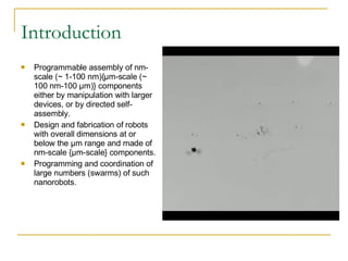
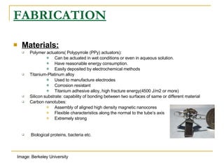
The document discusses the challenges and opportunities in developing micro robots at the micrometer scale. It covers fabrication methods using materials like polymers, metals and carbon nanotubes. It also discusses actuators, sensors like cantilever sensors, and applications in medical, industrial and space domains. Future directions include realizing self-assembling microfactories and using micro robots for hazardous applications.
Introduction Programmable assemblyof nm-scale (~ 1-100 nm){μm-scale (~ 100 nm-100 μm)} components either by manipulation with larger devices, or by directed self-assembly. Design and fabrication of robots with overall dimensions at or below the μm range and made of nm-scale {μm-scale} components. Programming and coordination of large numbers (swarms) of such nanorobots.
4.
FABRICATION Materials: Polymeractuators( Polypyrrole (PPy) actuators): Can be actuated in wet conditions or even in aqueous solution. Have reasonable energy consumption. Easily deposited by electrochemical methods Titanium-Platinum alloy Used to manufacture electrodes Corrosion resistant Titanium adhesive alloy, high fracture energy(4500 J/m2 or more) Silicon substrate: capability of bonding between two surfaces of same or different material Carbon nanotubes: Assembly of aligned high density magnetic nanocores Flexible characteristics along the normal to the tube’s axis Extremely strong Biological proteins, bacteria etc. Image: Berkeley University
5.
Actuator-Rotary Nanomachine. Thecentral part of a rotary nanomachine.(Figure courtesy of Prof. B. L. Feringa’s group (Univ of Groningen.) Power is supplied to these machines electrically, optically, or chemically by feeding them with some given compound. Rotation due to orientation in favorable conformation Subject to continuous rotation
6.
Drawbacks of molecularmachines of This Kind Moving back and forth or rotating continuously Molecules used in these machines are not rigid Wavelength of light is much larger than an individual machine . Electrical control typically requires wire connections . The force/torque and energy characteristics have not been investigated in detail. Rotary Nanomachine.
7.
Motor run by Mycoplasma mobile Image credit: Yuichi Hiratsuka, et al. Bacterium moves in search of protein rich regions. The bacteria bind to and pull the rotor. Move at speeds of up to 5 micrometers per second. Tracks are designed to coax the bacteria into moving in a uniform direction around the circular tracks. Protrusions
8.
Motion of aMycoplasma mobile -driven rotor . Image credit: Yuichi Hiratsuka, et al. Some Other Types: Chlamyodomonas : Swim toward light (phototaxis) Dictyostelium amoeba crawl toward a specific chemical substance (chemotaxis). Each rotor is 20 micrometers in diameter
9.
Cantilever Sensors Departmentof Physics and Physical Oceanography, Memorial University, St. John’s, Newfoundland,Canada θ=Angle of incidence Φ=Azimuthal angle Nc is the surface normal to cantilever ξ = Angle of inclination of PSD
10.
Cantilever Sensors Detection Mechanisms Detect the deflection of a cantilever caused by surface stresses Measure the shift in the resonance frequency of a vibrating cantilever Drawbacks Inherent elastic instabilities at microscopic level Difficult to fabricate nanoscale cantilevers Image: L. Nicu, M. Guirardel, Y. Tauran, and C. Bergaud (a) cantilevers (b) bridges. Optical microscope images of SiNx:
11.
Micro-Electro-Mechanical-System 60 μmby 250 μm by 10 μm Turning radius 160 μm Speed over 200 μm/s Average step size 12 nm Ability to navigate complex paths
12.
The state transitiondiagram of USDA Bruce R. Donald , Member, IEEE , Christopher G. Levey , Member, IEEE , Craig D. McGray , Member, IEEE , Igor Paprotny, and Daniela Rus
13.
Configuration Space BruceR. Donald , Member, IEEE , Christopher G. Levey , Member, IEEE , Craig D. McGray , Member, IEEE , Igor Paprotny, and Daniela Rus
14.
Steering Arm subsystemDimple dimension .75 μm Disk radius 18 μm Cantilever beam 133 μm long Controls direction by raising and lowering the arm Simultaneous operation with scratch drive Control in the form of oscillating voltages Bruce R. Donald , Member, IEEE , Christopher G. Levey , Member, IEEE , Craig D. McGray , Member, IEEE , Igor Paprotny, and Daniela Rus
15.
Control Waveforms Drivewaveform actuates the robot Forward waveform lowers the device voltage Turning waveform increases the device voltage Bruce R. Donald , Member, IEEE , Christopher G. Levey , Member, IEEE , Craig D. McGray , Member, IEEE , Igor Paprotny, and Daniela Rus
16.
Power delivery mechanismUses insulated electrodes on the silicon substrate Forms a capacitive circuit with scratch drive Actuator can receive consistent power in any direction and position No need of position restricting wires Bruce R. Donald , Member, IEEE , Christopher G. Levey , Member, IEEE , Craig D. McGray , Member, IEEE , Igor Paprotny, and Daniela Rus
17.
Device Fabrication Surfacemicromachining process: Consists of three layers of polycrystalline silicon, separated by two layers of phosphosilicate glass. The base of the steering arm is curled so that the tip of the arm is approximately 7.5 μm higher than the scratch drive plate Layer of tensile chromium is deposited to create curvature Bruce R. Donald , Member, IEEE , Christopher G. Levey , Member, IEEE , Craig D. McGray , Member, IEEE , Igor Paprotny, and Daniela Rus
18.
Electrical Grids Consistof an array of metal electrodes on a silicon substrate. Electrodes are insulated from the substrate by a 3 μm thicklayer of thermal silica Coated with 0.5 of zirconium dioxide High-impedance dielectric coupling Silicon wafers: oxidized for 20 h at 1100C in oxygen Wafers are patterned with the “Metal” pattern Three metal layers are evaporated onto the patterned substrates Middle layer consists of gold-Conductive Two layers of chromium-adhesion layers between the gold, the oxidized substrate, and the zirconium dioxide Bruce R. Donald , Member, IEEE , Christopher G. Levey , Member, IEEE , Craig D. McGray , Member, IEEE , Igor Paprotny, and Daniela Rus
19.
Some Other KindsPiezoelectric motors for mm Robots Not required to support an air gap Mechanical forces are generated by applying a voltage directly across the piezoelectric film. Ferroelectric thin films (typically 0.3-μm), intense electric fields can be established with fairly low voltages. High torque to speed ratios. μ Robots Driven by external Magnetic fields Include a permanent magnet Can be remotely driven by external magnetic fields Suitable for a mobile micro robot working in a closed space. Pipe line inspection and treatment inside human body. Anita M. Flynn, Lee S. Tavrow, Stephen F. Bart and Rodney A. Brooks MIT Artificial Intelligence Laboratory
20.
Applications See andmonitor things never seen before Medical applications such as cleaning of blood vessels with micro-robots Military application in spying Surface defect detection Building intelligent surfaces with controllable (programmable) structures Tool for research and education Micro robot interacting with blood cells
Future Scope Realizationof ‘Microfactories’ Self assembling robots Use in hazardous locations for planning resolution strategies Search in unstructured environments, surveillance Search and rescue operations Space application such as the ‘Mars mission’ Self configuring robotics (change shape) Micro-machining
23.
Acknowledgements B. L. Feringa, “In control of motion: from molecular switches to molecular motors,” Acc. Chem. Res., vol. 34, no. 6, pp. 504–513, June 2001. H. C. Berg, Random Walks in Biology. Princeton, NJ: Princeton Univ. Press, 1993. http://www.physorg.com/news79873873.html K.R. Udayakumar, S.F. Bart, A.M. Flynn, J.Chen, L.S. Tavrow, L.E. Cross, R.A. Brooks and D.J.Ehrlich, “Ferroelectric Thin Film Ultrasonic Micromotors”Fourth IEEE Workshop on Micro Electro Mechanical Systems, Nara, Japan, Jan. 30 - Feb. 2, 1991. JOURNAL OF MICROELECTROMECHANICAL SYSTEMS, VOL. 15, NO. 1, FEBRUARY 2006 1An Untethered, Electrostatic, Globally Controllable MEMS Micro-Robot Bruce R. Donald, Member, IEEE, Christopher G. Levey, Member, IEEE, Craig D. McGray, Member, IEEE,Igor Paprotny, and Daniela Rus K.W. Markus, D. A.Koester, A. Cowen, R. Mahadevan,V. R. Dhuler,D.Roberson, and L. Smith, “MEMS infrastructure: The multi-user MEMSprocesses (MUMPS),” in Proc. SPIE—The Int. Soc. Opt. Eng., Micromach.,Microfabr. Process Technol., vol. 2639, 1995, pp. 54–63.