PID Piping & Instrumentation Diagram Schematic Explained
•Download as PPT, PDF•
5 likes•546 views

The Piping and Instrumentation Diagram

Recommended
Recommended
More Related Content
What's hot
What's hot (20)
Viewers also liked
Viewers also liked (20)
Similar to PID Piping & Instrumentation Diagram Schematic Explained
Similar to PID Piping & Instrumentation Diagram Schematic Explained (20)
Recently uploaded
Recently uploaded (20)
PID Piping & Instrumentation Diagram Schematic Explained
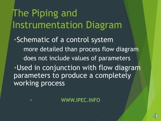
- 1. The Piping and Instrumentation Diagram •Schematic of a control system –more detailed than process flow diagram –does not include values of parameters •Used in conjunction with flow diagram parameters to produce a completely working process • WWW.IPEC.INFO
- 2. Line Types Connect different units in controlled system
- 3. Identification Letters First letter represents parameter to be controlled, not the action used to control that parameter Second letter is the type of control device
- 4. Actuator Symbols Used to activate process control equipment
- 5. Transmitters • Sensors used to measure parameters • Send information to actuators to control process • Location depends on application • Set points, indicated by dots, show specific location
Editor's Notes
- Schematic contains symbols that precisely describe each component of a control system such as sensors, controllers, line connections, reactors Components are uniquely labeled for size, content, connection type, status
- Lines are used to connect different units in the controlled system.
- Transmitters are described using identification letters. The first letter represents the parameter to be controlled while the second letter represents the type of control device.
- Actuators are used to activate process control equipment.
- Transmitters are sensors used to measure parameters. This information is then sent to actuators which control the process. A set point shows the specific location of a transmitter and are represented by dots.
- This is a three element control design of a steam drum used to separate steam from boiling water. It is imperative that the level of water be precisely controlled as a low level of water can cause a catastrophic explosion. If the level gets too high then droplets will spill over into the steam stream and potentially damage equipment that the steam is being fed too. The main element measures the level of water in the tank. The level is measured by level transmitter 1 at the top and bottom of the tank. The signal goes through level relay 1 to level indicator controller 1 which controls flow valve 3 and consequently the boiler feed water stream. Inconsistencies in the boiler feed water as measured by flow transmitter 3 and temperature transmitter 3 are compensated by flow indicator controller 1 changing flow valve 3. To control steam density the exiting steam is measured by Pressure Transmitter 2, Temperature Transmitter 2, and Flow Transmitter 2, which send a signal to Flow Indicator controller 3 to control Flow Valve 3.