1
MEM 160: WORKSHOPPRACTICE
CHAPTER 3
MEASURING INSTRUMENT, GAUGES AND
MARKING OUT TOOLS
2.
2
OBJECTIVES & LEARNINGOUTCOMES
1. Describe common measuring
instruments, gauges and marking
out tools in mechanical workshop.
2. Select suitable measuring
instruments, gauges and marking
out tools in engineering application.
3. Use accurately common measuring
instruments, gauges and marking
out tools in engineering application.
3.
3
3. INTRODUCTION
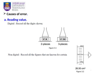
1. Whywe need measurement?.
a. To make things, either own design or somebody else’s.
b. To control the way other people make things. (industry-mass
production)
c. For scientific description. (comparison between stone &
wood-weight)
2. Precise measurement usually required when fitting or
assembling 2 separate parts together.
3. To archive the precise measurement, not only the
measurement instrument need to be precisely produced but
the method of using it also need to be correct.
4.
4
4. If someonemeasure same thing, exactly with the same
measurement instrument, the measurement reading or result
may not be exactly same. This phenomenon called as error in
measurement.
5. Error in measurement not means that our reading have
mistake, but is a mathematical way to show the uncertainty in
the measurement.
6. Errors can be minimized but cannot be eliminated.
9
3.1.1 Vernier Caliper
3.1 VERNIER SCALE
WHAT? – A precision instrument that can be used to measure
internal, external step and depth measurement.
ACCURACY? – Accurate to within 0.001 inch or 0.02 mm,
depending to the unit whether imperial or
metric.
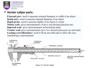
FEATURES: Generally has a L shape design with a moveable arm.
13
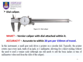
Dial caliper.
WHAT?– Vernier caliper with dial attached within it.
ACCURACY? – Accurate to within 20 µm per 150mm of travel.
Figure 3.5 Dial caliper
14.
14
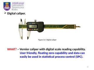
Digital caliper.
WHAT?– Vernier caliper with digital scale reading capability.
User friendly, floating zero capability and data can
easily be used in statistical process control (SPC).
Figure 3.6 Digital caliper
15.
15
3.1.2 Vernier HeightGauges
WHAT? – A sort of vernier caliper with a special base block and
other attachment which make suitable for height
measurement.
ACCURACY? – Vertical distance accurate to within +/- 0.001
inch or 0.02 mm, depending to the unit whether
imperial or metric.
PURPOSE? – Mainly used to inspect part or layout work.
16.
16
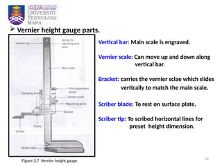
Vernier heightgauge parts.
Figure 3.7 Vernier height gauge
Vertical bar: Main scale is engraved.
Vernier scale: Can move up and down along
vertical bar.
Bracket: carries the vernier sclae which slides
vertically to match the main scale.
Scriber blade: To rest on surface plate.
Scriber tip: To scribed horizontal lines for
preset height dimension.
17.
17
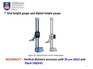
Dial heightgauge and digital height gauge
ACCURACY? – Vertical distance accuracy until 20 µm (dial) and
10µm (digital).
Figure 3.8 Digital and dial vernier height gauge
18.
18
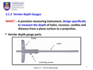
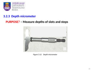
3.1.3 Vernier depthGauges
WHAT? – A precision measuring instrument, design specifically
to measure the depth of holes, recesses, cavities and
distance from a plane surface to a projection.
Vernier depth gauge parts.
Figure 3.9 Vernier depth gauge
20
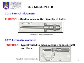
3. 2 MICROMETER
3.2.1Internal micrometer
PURPOSE? – Used to measure the diameter of holes.
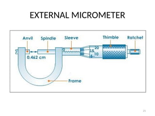
3.2.2 External micrometer
Figure 3.10 Internal micrometer
PURPOSE? – Typically used to measure wires, spheres, shaft
and block.
Figure 3.11 External micrometer
25
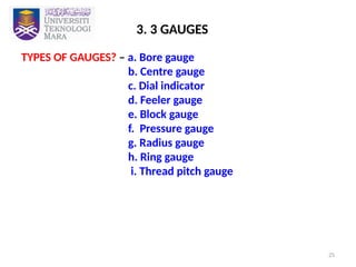
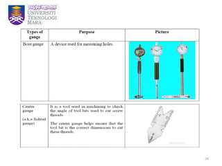
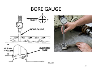
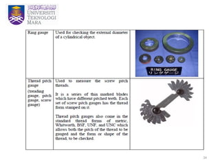
3. 3 GAUGES
TYPESOF GAUGES? – a. Bore gauge
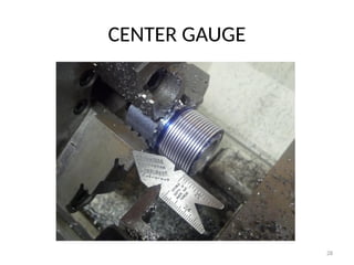
b. Centre gauge
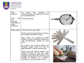
c. Dial indicator
d. Feeler gauge
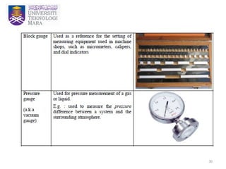
e. Block gauge
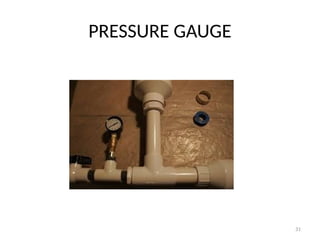
f. Pressure gauge
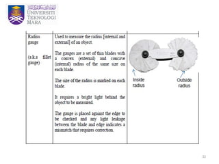
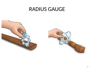
g. Radius gauge
h. Ring gauge
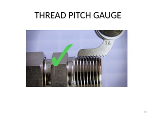
i. Thread pitch gauge
36
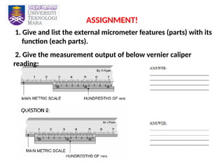
ASSIGNMENT!
1. Give andlist the external micrometer features (parts) with its
function (each parts).
2. Give the measurement output of below vernier caliper
reading:
37.
37
REFERENCES
1. Bawa, H.S. (1995). Workshop Technology. New Delhi, Tata McGraw-Hill.
2. Kalpakjian, S & Schmid, S. R. (2010). Manufacturing Processes
for Engineering Materials, 6th
edition, Prentice Hall.
3. Farrah, N. (2013). Introduction to Bench Fitting [PDF document].
Retrieved from http://i-learn.uitm.edu.my/v2/
4. Rao, P.N. (2001), Manufacturing Technology : Foundry, Forming and
Welding. New Delhi, Tata McGraw-Hill.


![37
REFERENCES
1. Bawa, H. S. (1995). Workshop Technology. New Delhi, Tata McGraw-Hill.
2. Kalpakjian, S & Schmid, S. R. (2010). Manufacturing Processes
for Engineering Materials, 6th
edition, Prentice Hall.
3. Farrah, N. (2013). Introduction to Bench Fitting [PDF document].
Retrieved from http://i-learn.uitm.edu.my/v2/
4. Rao, P.N. (2001), Manufacturing Technology : Foundry, Forming and
Welding. New Delhi, Tata McGraw-Hill.](https://image.slidesharecdn.com/mem160chapter3-250506151811-2737b0b3/85/MEM-160-Chapter-3-Measurement-tool-1-pptx-37-320.jpg)


