Download as PDF, PPTX


![Entropy Change
S = 0
S1 = S2
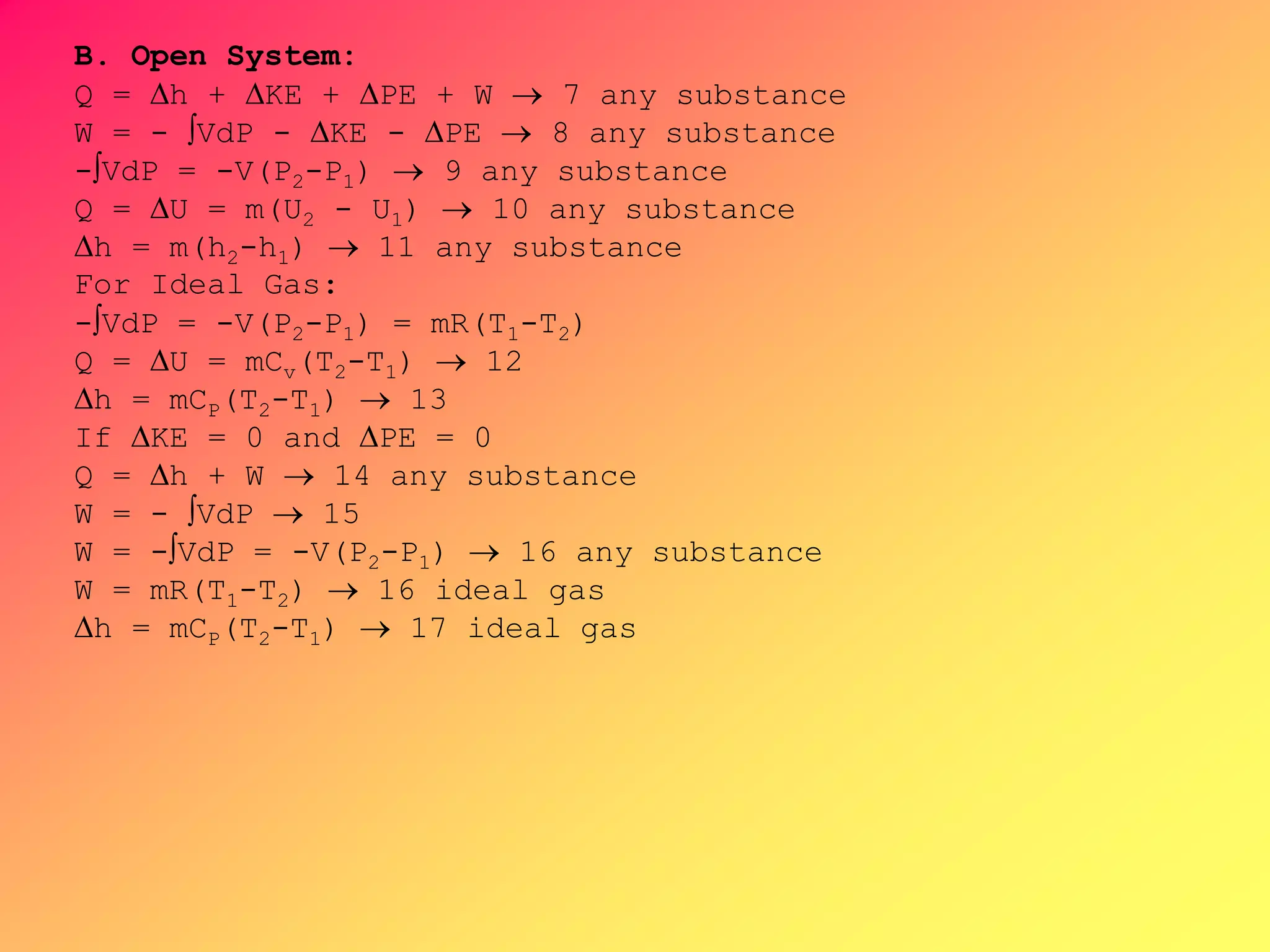
B. Open System (Steady Flow)
Q = h + KE + PE + W 10 any substance
W = - VdP - KE - PE 11 any substance
h = m(h2-h1) 12 any substance
Q = 0
W = -h - KE - PE 13
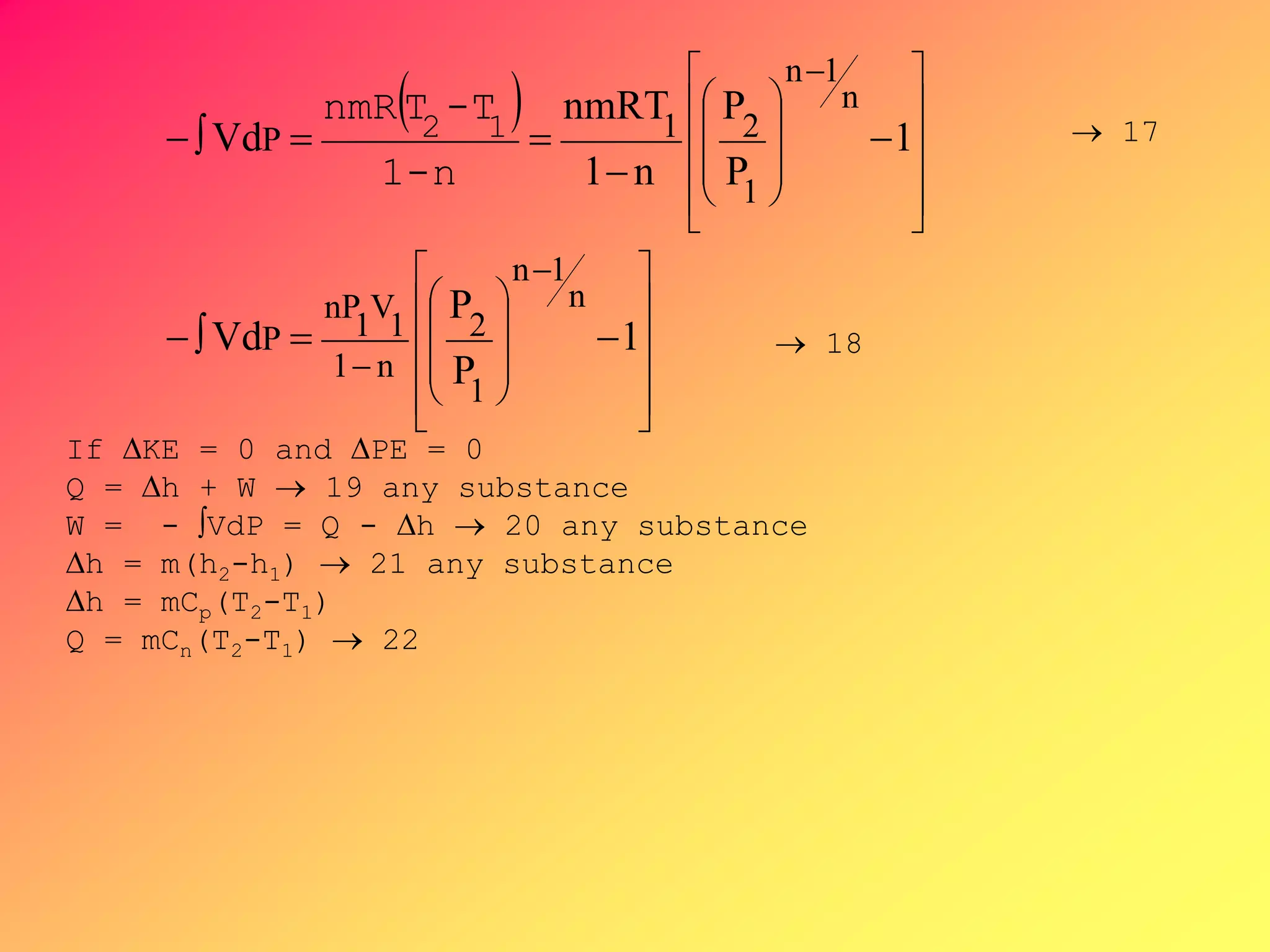
From PVk = C ,V =[C/P]1/k, substituting V to
-∫VdP, then by integration,](https://image.slidesharecdn.com/thermodynamics1-200605000701/75/ME-12-F1-MODULE-Thermodynamics-1-67-2048.jpg)


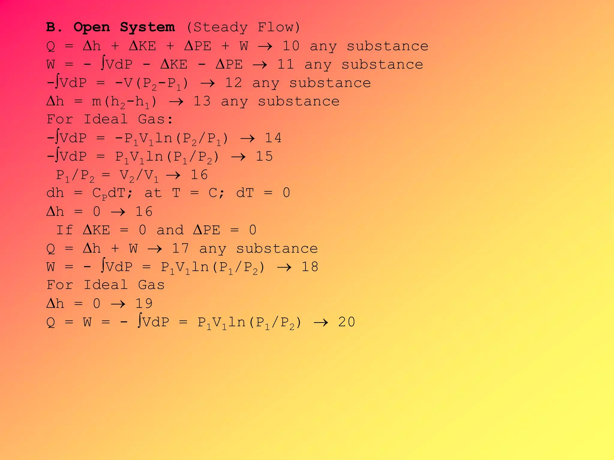
![B. Open System (Steady Flow)
Q = h + KE + PE + W 11
W = - VdP - KE - PE 12
h = m(h2-h1) 13
Q = mCn(T2-T1) 14
dQ = mCn dT
W = Q - h - KE - PE 15
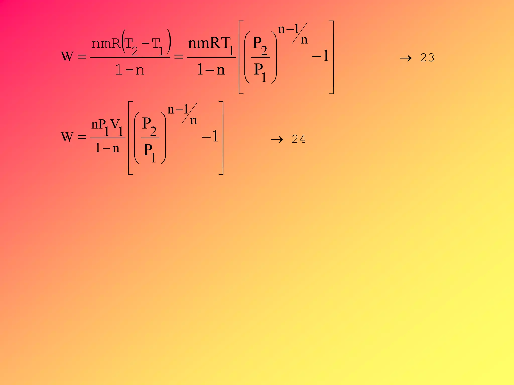
From PVn = C ,V =[C/P]1/n, substituting V to
-∫VdP, then by integration,
n1
n
VdP
nVdP
1122
V-PVP
PdV
16](https://image.slidesharecdn.com/thermodynamics1-200605000701/75/ME-12-F1-MODULE-Thermodynamics-1-74-2048.jpg)


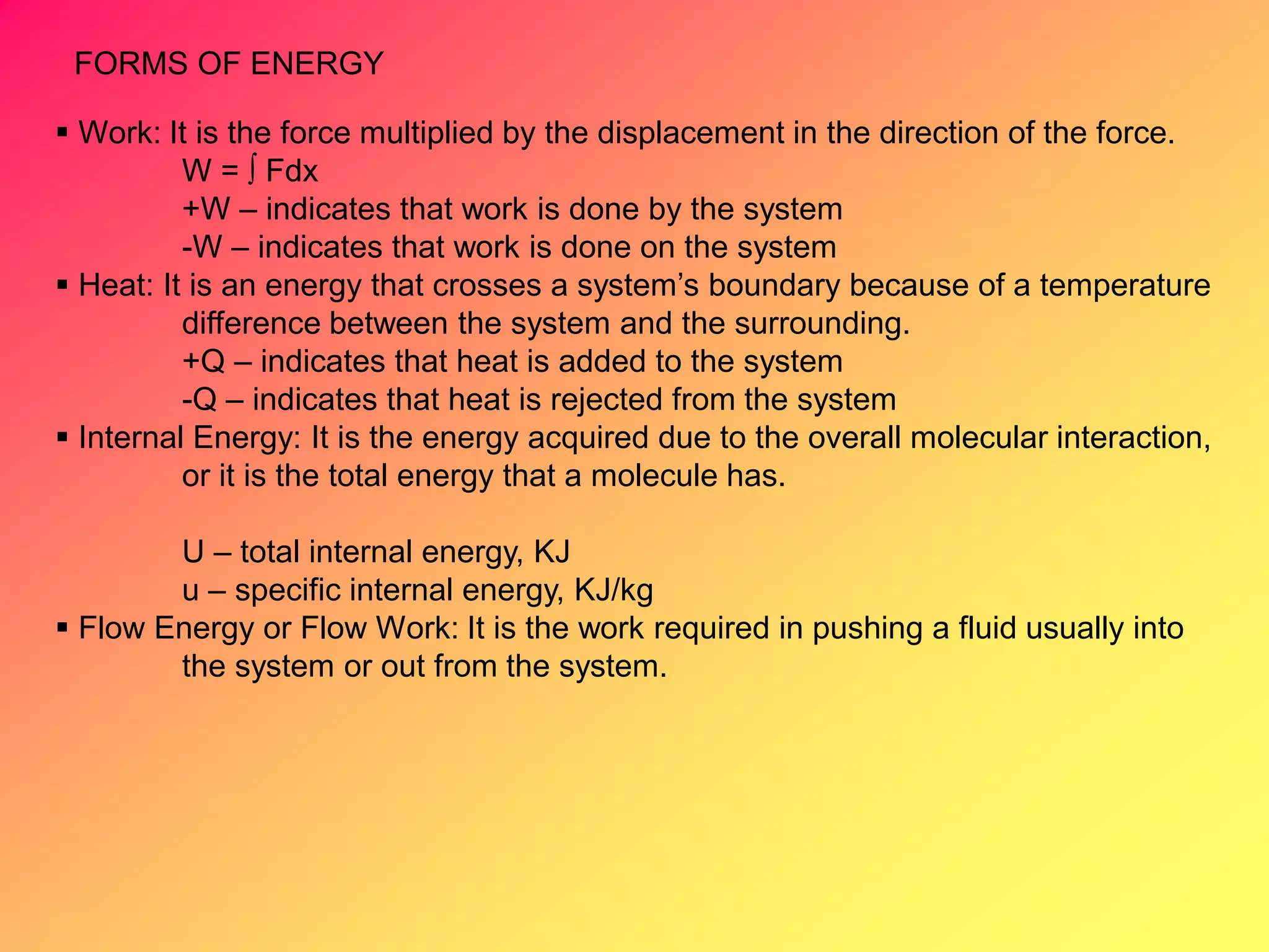
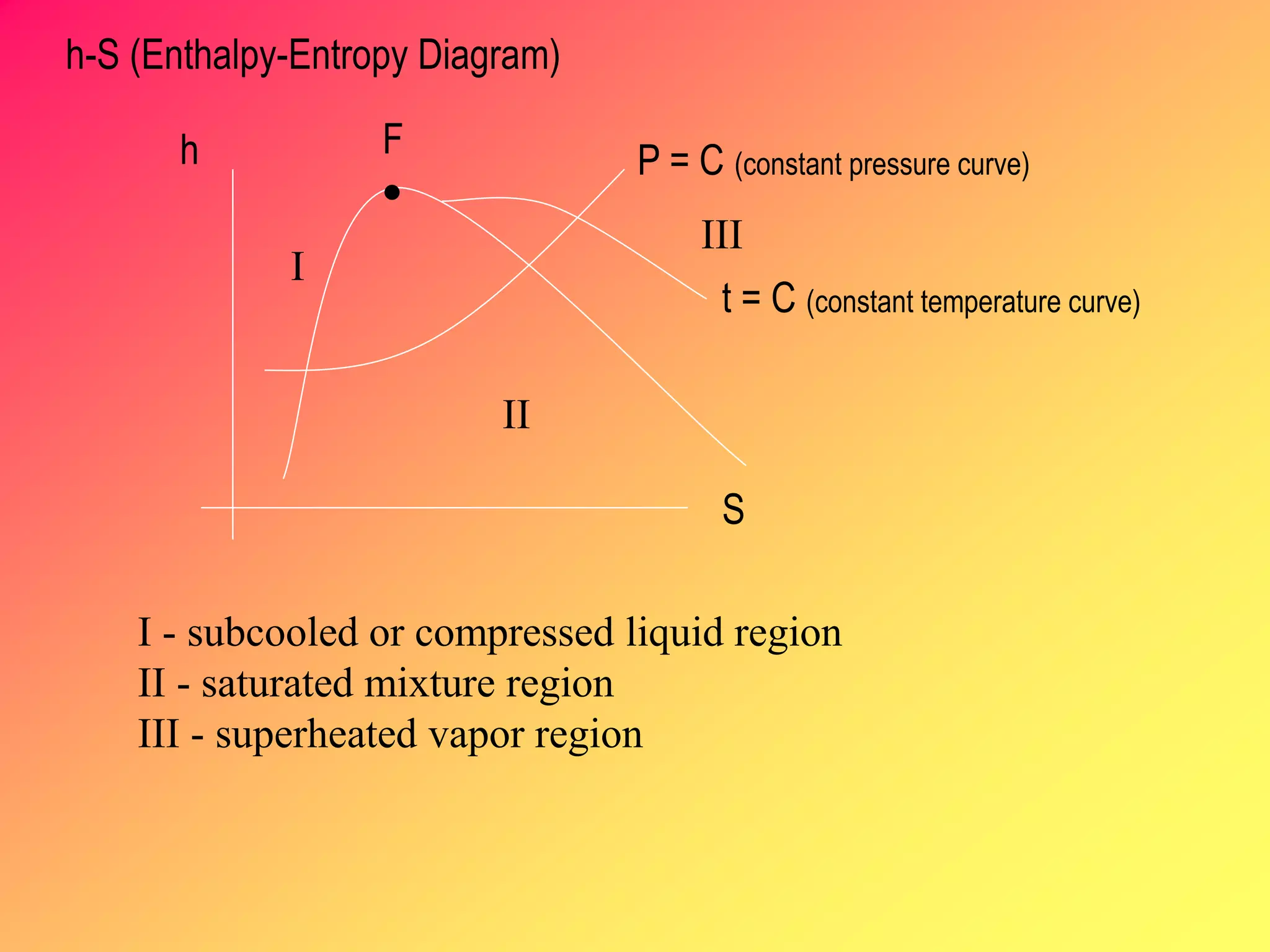
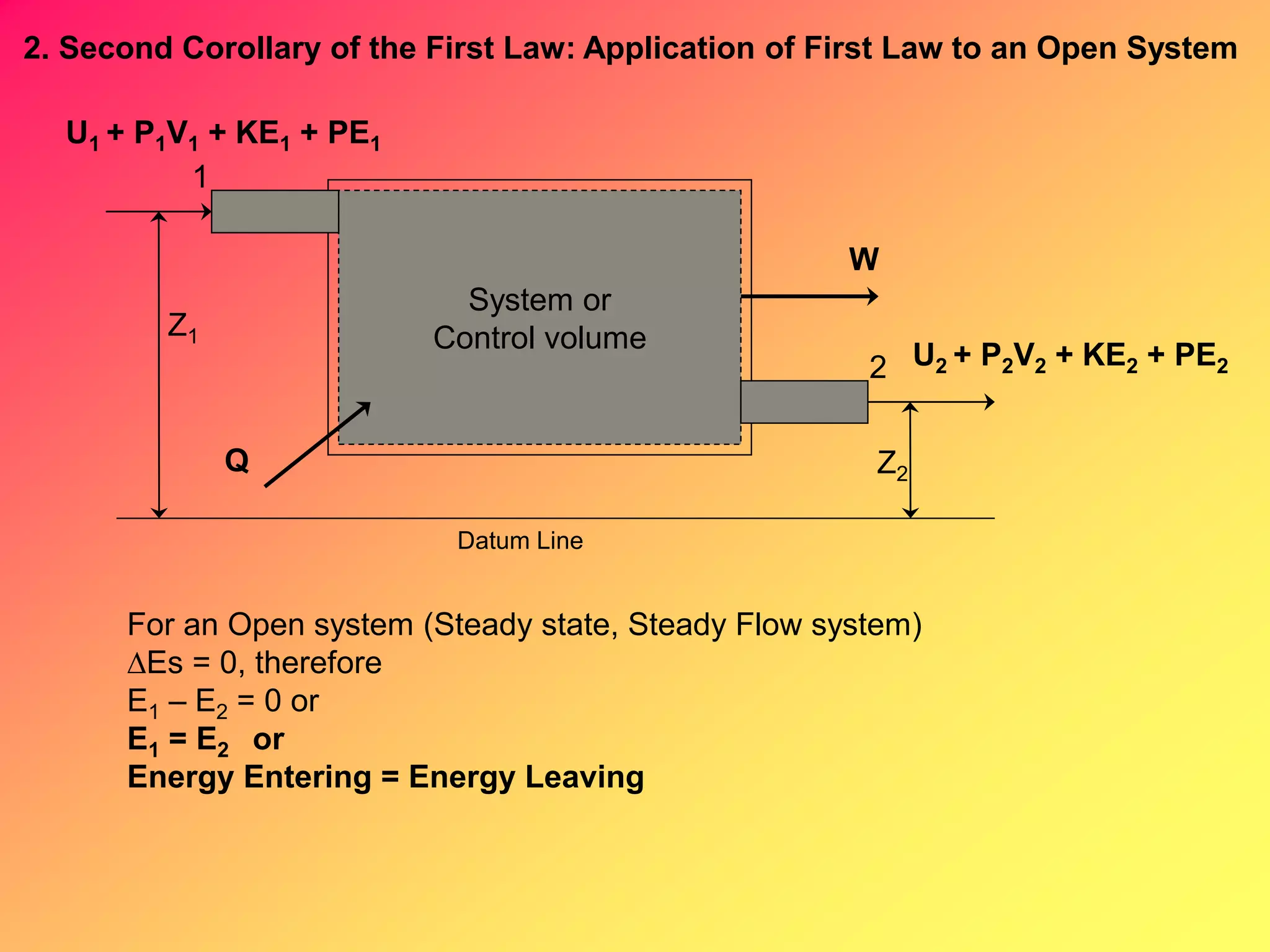
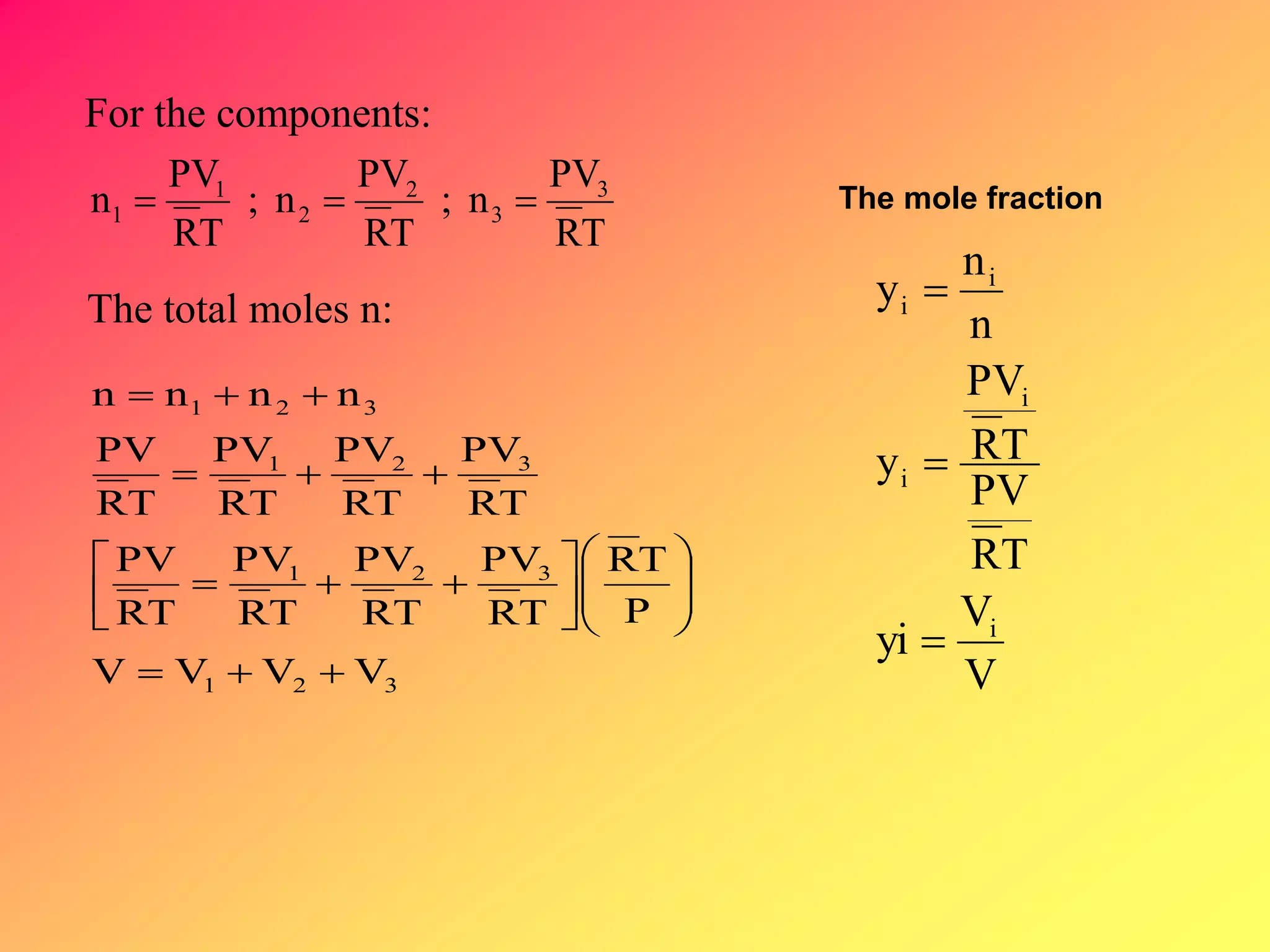
Thermodynamics is the science dealing with energy transformation between heat and work. It studies systems, which can be open or closed to matter flow, and their surroundings. For a closed system, there is no exchange of mass between the system and surroundings, while an open system allows mass flow. A process is a change in state of a substance, and a cycle occurs when the initial and final states are the same. Thermodynamics analyzes the various forms of energy including work, heat, internal energy, and flow energy. It also examines the properties of pure substances and how they vary with changes in temperature and pressure through different phases like solid, liquid, and gas.


