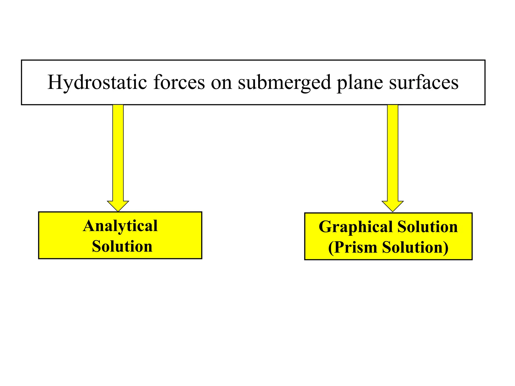
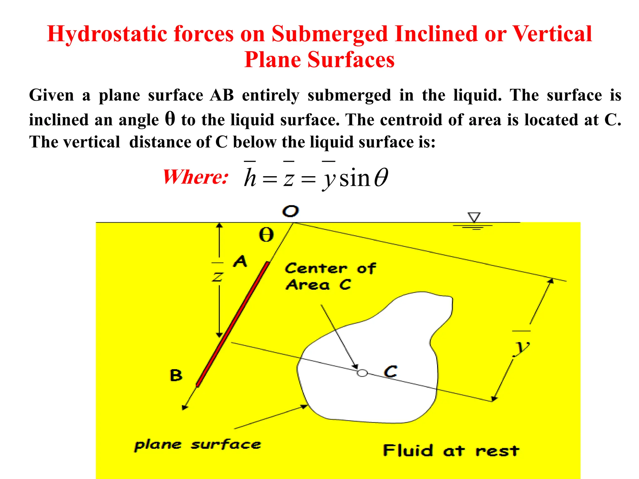
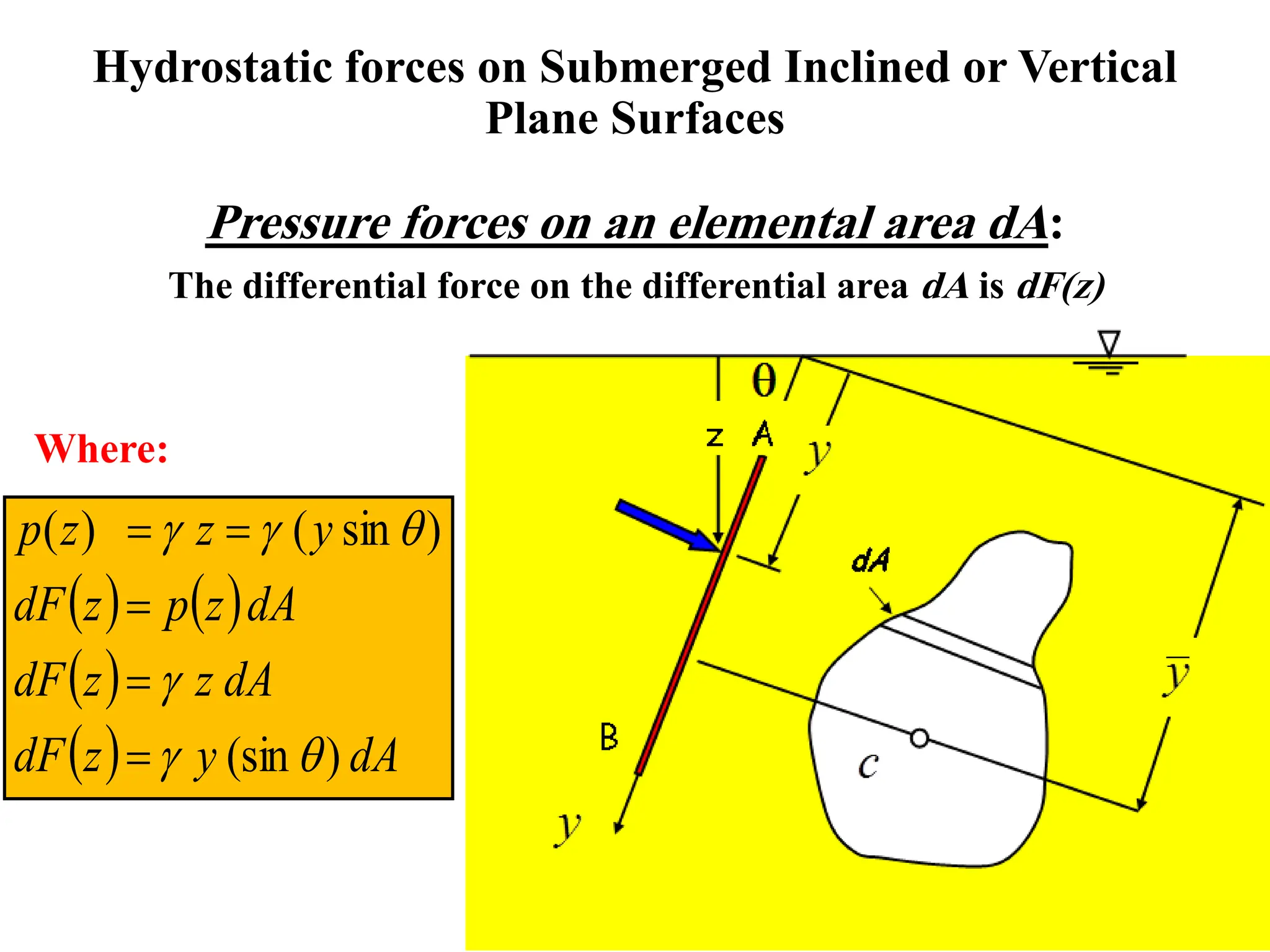
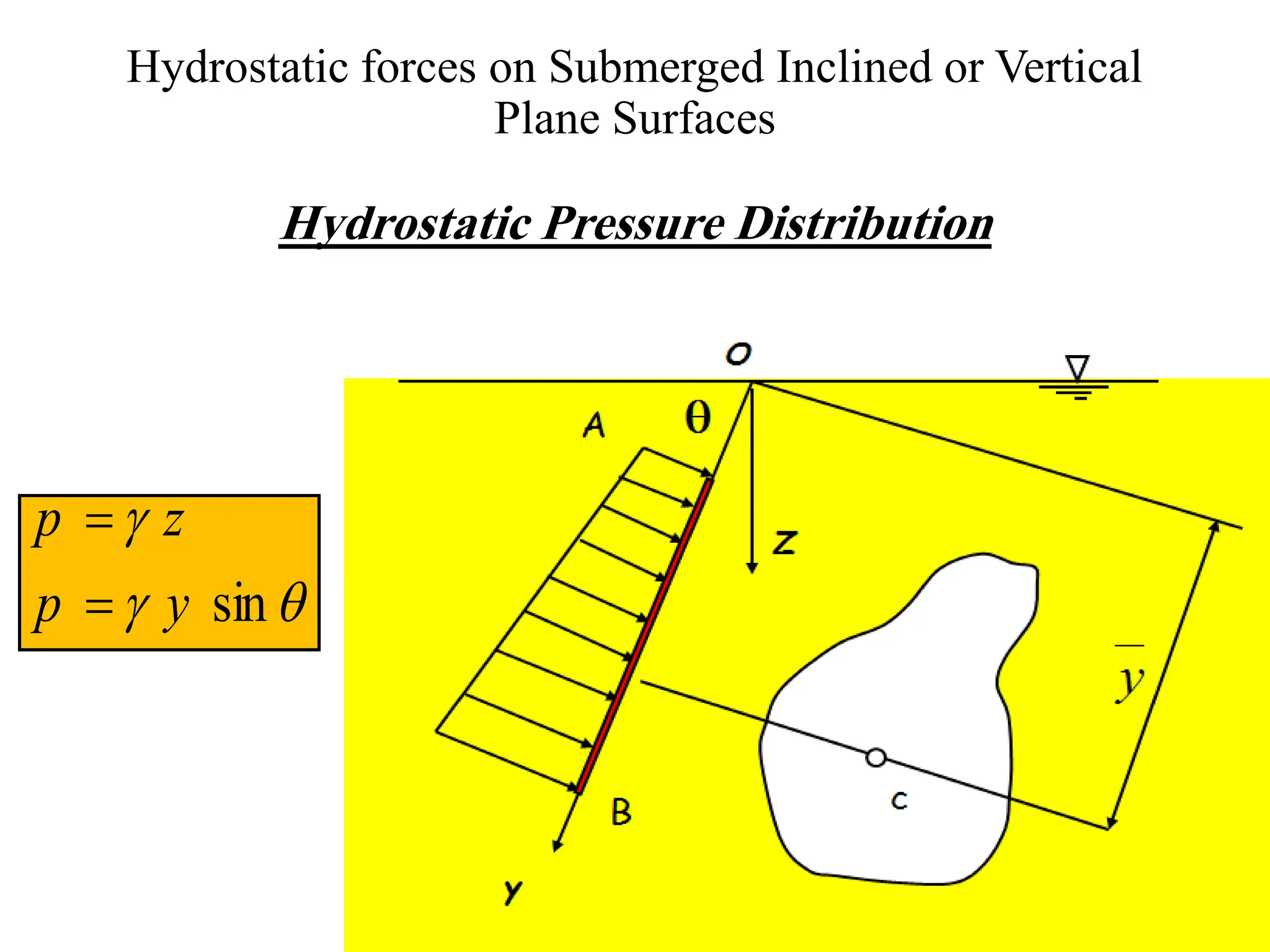
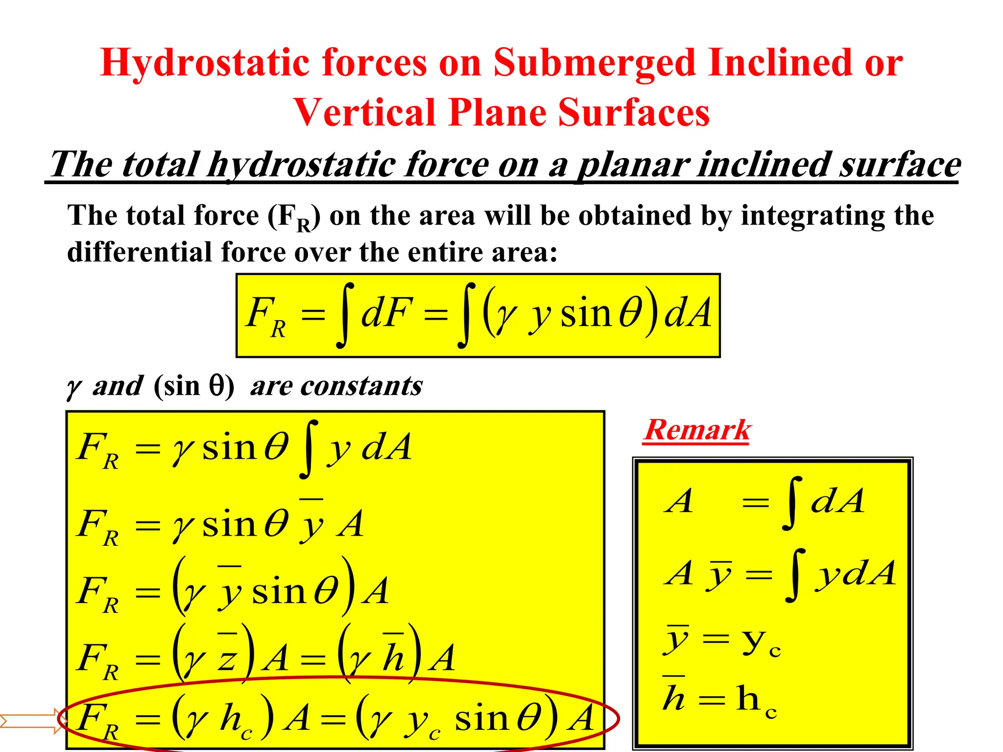
The document discusses hydrostatic forces on submerged plane surfaces. It provides analytical and graphical (prism) methods to calculate the total hydrostatic force and location of the center of pressure. As an example, it applies both methods to calculate the force on a submerged car door located 8 meters below the water surface. The analytical method yields a force of 101.24 kN and center of pressure at 0.144 meters above the bottom of the door. The prism method gives a force of 176.94 kN and center of pressure at 2.1 meters above the bottom.


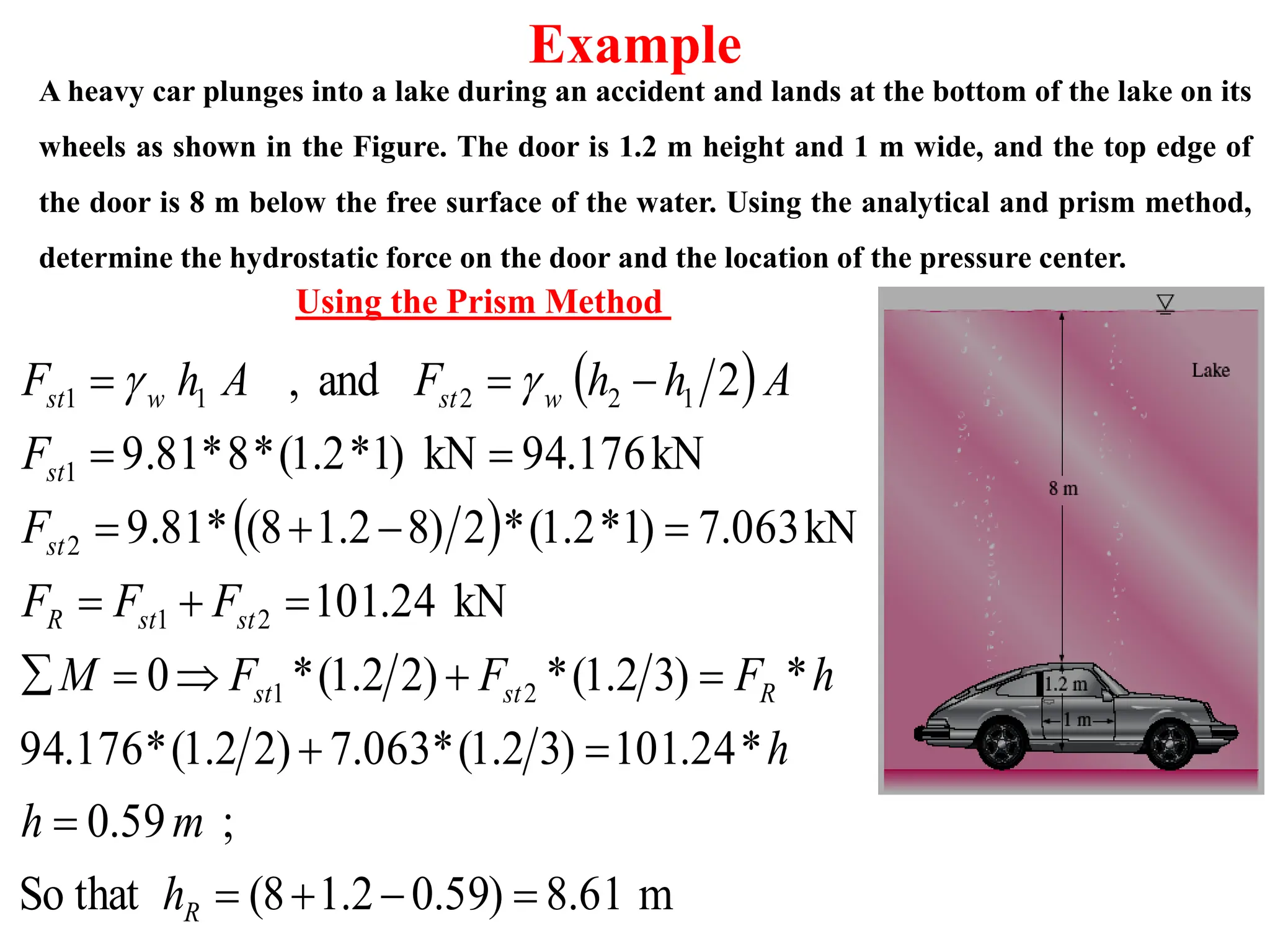
![A heavy car plunges into a lake during an accident and lands at the bottom of the lake on its
wheels as shown in the Figure. The door is 1.2 m height and 1 m wide, and the top edge of
the door is 8 m below the free surface of the water. Using the analytical and prism method,
determine the hydrostatic force on the door and the location of the pressure center.
Example
m
8.61
)]
2
1.2
(
[8
1.2)
*
1
(
)]
2
1.2
(
[8
0.144
144
.
0
)
12
1.2
*
1
(
)
12
(
I
h
h
I
kN
101.24
kN
)
1
*
2
.
1
(
*
)]
2
1.2
(
[8
*
9.81
kN/m
9.81
and
4
3
3
xc
c
c
xc
3
R
R
R
R
w
c
w
R
h
m
ba
A
h
F
F
A
h
F
Using the Analytical Method](https://image.slidesharecdn.com/lecture4-fluid1-hydrostaticforcesonsubmergedplanesurfaces-240221061833-f7bb4324/75/Lecture-4-Fluid-1-Hydrostatic-Forces-on-Submerged-Plane-Surfaces-pdf-20-2048.jpg)


![Chapter 3 static forces on surfaces [compatibility mode]](https://cdn.slidesharecdn.com/ss_thumbnails/chapter-3-static-forces-on-surfaces-compatibility-mode-160214035852-thumbnail.jpg?width=640&height=640&fit=bounds)


![Chapter Four [Repaired].pptx](https://cdn.slidesharecdn.com/ss_thumbnails/chapterfourrepaired-230317125646-7f640ad0-thumbnail.jpg?width=640&height=640&fit=bounds)


