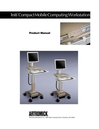
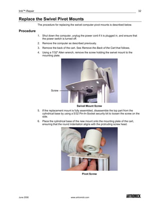
The document is a product manual for the Initi Compact Mobile Computing Workstation by Artromick. It provides an overview of the cart's features and specifications. The manual also contains instructions for setting up, using, and troubleshooting the cart, as well as sections on repair, warranty information, and an index.
Artromick Nx10 Reference Manual August 2007 for Hospital Computing SolutionsArtromick
The document provides instructions for setting up the Artromick NX10 Workstation mobile computing cart. It describes removing the cart from its shipping packaging by opening the container, lifting it out using proper lifting techniques, and inspecting it for damage. It also covers transporting, storing, and performing the basic setup of the cart.
Artromick Mcm Manual for Hospital Computing SolutionsArtromick
The document is a product manual for the Initi Mobile Computing MedServer cart. It provides an overview of the cart's features and specifications, instructions for setup and use, programming the cart using host software or the keypad, troubleshooting, and repair procedures. The manual is divided into chapters covering these topics and is intended to guide users, administrators, installers and technicians.
This document provides information about maintaining and servicing Compaq 325 and 326 Notebook PCs and HP 425 and 625 Notebook PCs. It covers product descriptions, external component identification, an illustrated parts catalog, and removal and replacement procedures. Safety warnings are provided and components that can be accessed and replaced by customers or by a technician are described in detail, along with the tools required. Electrostatic discharge safety precautions are also outlined.
Artromick Auto Lock Manual for Hospital Computing SolutionsArtromick
Here are the key steps to initially set up your cart:
1. Place the cart in its intended location, allowing enough space around it for operation and access. Ensure the floor surface can support the cart's weight.
2. Remove any protective wrapping or packaging from the cart.
3. Extend the casters by pressing down on the foot pedal under each caster bracket until each wheel is fully extended and locks into place.
4. Plug the power cord into the cart's power inlet located at the back of the cart. Then plug the other end into a properly grounded wall outlet.
5. Turn the power switch located at the back of the cart to the "On" position. The keypad will
Artromick Ac Usersguide304 for Hospital Computing SolutionsArtromick
This user can access the cart using an access code or card, but cannot perform
programming functions. This user is responsible for accessing the cart to retrieve or restock
medications.
Key User: This user has the same access privileges as a Normal user, but
also has the ability to use the Override Code to access the cart outside of
normal access parameters. This user is typically responsible for restocking the
cart.
Guest: This user has limited access to the cart and is typically a temporary
user. This user can access the cart using an access code or card, but has no
programming privileges.
Override Rights The Override Code provides authorized users with a special means of access that
bypasses alarms
This document provides an instruction manual for the Meade ETX-90AT, ETX-105AT, and ETX-125AT Astro Telescopes. It describes the key features of the telescopes including the optical tube, viewfinder, setting circles, locks, and computer control panel. It provides instructions on assembly, alignment, focusing, and basic operation using the arrow keys to manually move the telescope or let Autostar automatically track objects. The document also outlines Autostar's menu system and provides information on additional features and accessories.
The document provides a user guide for the Spartan-3E Starter Kit Board, covering its key components and features. The board includes switches, buttons, LEDs, and multiple clock sources. It is intended for learning Xilinx FPGA and software basics as well as for more advanced development. The guide describes the purpose and operation of each component and how to interface with them in a design.
This document is the user's guide for VirtualReScan 4.2. It provides information on operating VirtualReScan (VRS), a software for processing scanned images. The guide covers selecting scan sources, configuring VRS settings before scanning, using the VRS Interactive Viewer interface, and previewing images. It also describes the VRS workflow, available features, certified scanning applications, and the difference between certified and non-certified scanners.
Cấu hình máy được đánh giá ở mức khá, có card đồ họa rời
Đầy đủ những cổng kết nối ngoại vi phổ biến nhất hiện nay
Loa ngoài lớn đồng thời sở hữu hệ thống tản nhiệt tốt
Giá cả của máy vô cùng phải chăng, phù hợp nhiều đối tượng
Nguồn: https://laptops.vn/san-pham/dell-vostro-3568/
The document is an operations manual for a Humminbird fishfinder. It provides instructions on operating the device, including an overview of how sonar works, descriptions of the different views available, and explanations of the menu system and key functions. It also includes troubleshooting tips and specifications for the device.
This document is the instruction manual for the Datavideo SE-500 4-channel video mixer/switcher. It includes warnings and precautions, warranty information, an introduction to the product features, and sections describing how to connect video and audio sources, use the front and rear panel controls, select video formats and adjust levels, use transitions and effects, control via RS-232 and MIDI, and sample applications.
인터맥 CN51 모바일 컴퓨터는 1.5GHz 듀얼 코어 프로세서, 1GB RAM, 16GB 플래시 메모리에 Windows® 또는 Android ™ 운영 체제를 선택할 수있는 탁월한 다 기능성을 제공합니다.
탁월한 사용자 경험을 위해 설계된 CN51 산업용 PDA는 대형, 멀티 터치, 실외 판독 가능 화면은 스크롤을 줄이고 생산성을 높이며 판독이 용이 한 서명을 캡처 할 수있는 공간을 넓히면서 애플리케이션을 볼 수있는 충분한 공간을 제공합니다.
인터맥 CN51 바코드 PDA의 고성능 이미저는 모션 허용 오차와 스캐닝이 탁월하며, 저조도 스캐닝 환경에서도 최적의 바코드 스캐닝 기능을 제공하여 스캔 집약적인 애플리케이션에서 많은 시간과 사용자의 불만을 없애줍니다.
Intermec의 최첨단 이미지 처리 기술과 결합된 5 메가 픽셀 컬러 카메라는 바코드 판독 이상의 고급 기능을 제공합니다.
MDI (Mobile Document Imaging) 및 RDC (Remote Deposit Capture)는 이동 중에도 풀 사이즈 문서 또는 수표를 캡쳐하여 전자 파일로 변환 지점에서 본사로 전송하는 빠르고 안정적인 방법을 제공합니다.
Multi OS (O/S VERSATILITY)
Supports Microsoft® Windows Embedded Handheld 6.5 and Android™ 4.1 Operating Systems for flexible application support and migration.
DISPLAY
Large 4” brilliant WVGA multi-touch display allows for more graphical user interface, display-centric applications.
RUGGED
Withstands multiple 1.5m (5ft) drops to concrete across the operating temperature range and an IP64 seal rating against rain and dust.
SCANNING
Features best-in-class motion tolerance, and support for omnidirectional 1D & 2D barcode scanning.
FLEXIBLE NETWORK
Features WAN radio options with voice and data support including UMTS and Flexible Network UMTS/CDMA, PTT, as well as 802.11 a/b/g/n, Bluetooth, and GPS with GLONASS support.
BATTERY
Industry-leading performance that lasts a full shift and beyond, enhanced by smart battery technology.
PROCESSOR
Equipped with a power-efficient 1.5GHz dual core multi-engine Texas Instruments OMAP4 processor architecture, with 1GB RAM and 16GB Flash memory.
PHYSICAL CHARACTERISTICS
Dimensions with battery : L X W X D: 164 x 74 x 28 mm (base of unit) 32 mm (top of unit) (6.45 x 2.93 x 1.09-1.26 in)
Weight with battery : 350 g (12.3 oz)
POWER
Smart Battery Pack: 3.7V, 3900 mAh; Batteries are IEEE 1725 compliant, Li-Ion, removable, rechargeable.
OPERATING SYSTEM
Microsoft Windows Embedded Handheld v6.5 or Android v4.1*
MULTI-PROCESSOR ARCHITECTURE
Texas Instruments 1.5 GHz OMAP 4470 dual core, multi-engine processor architecture
MEMORY AND STORAGE
Memory: 1 GB RAM
ROM: 16 GB Flash
Customer - accessible miniSD slot for removable memory cards
DISPLAY
10.16 cm (4.0 in), 480 x 800 pixel (WVGA) TFT-LCD display
LCD supports 24 bpp color depth
LED backlight
Ambient light sensor
Resistive multi-touch touch panel
STANDARD COMMUNICATIONS
USB – High Speed 2.0 Host, USB – High Speed 2.0 Client
INTEGRATED CAMMERA OPTION
5 Megapixel auto focus color camera with LED flash
KEYPAD OPTIONS
(27 Key) Numeric or (43 Key) QWERTY with backlit keypad
ACCESSORIES
Supports all CN50 charging and docking accessories as well as FlexDock modular docking system, vehicle dock, vehicle holder, snap on adaptors, removable scan handle, and magnetic stripe reader.
>하이온아이티
주소 : 서울 금천구 가산디지털2로 165, 1304호 (백상스타타워2차)
대표번호 : 02-2038-0018 / 이메일 : hion@hionit.com
홈페이지 : http://hionsmart.com
This document is a user guide for the CV41 vehicle mount computer running Windows CE. It provides information about operating and maintaining the computer such as attaching and removing it from the mounting dock, using accessories like the touchscreen and keypad, connecting power and antennas, transferring files, and understanding the user interface and included applications. The guide also describes how to manage the computer within a network using Intermec's SmartSystems Foundation software and how to develop and install custom applications.
인터맥프린터 Intermec PX4i PX6i 열전사감열 RFID 산업용 바코드프린터 매뉴얼HION IT
인터맥, EasyCoder PX (PX4i, PX6i) 시리즈 바코드프린터는 까다로운 산업환경에 맞게 설계된 견고한 금속의 고성능 프린터로, 24시간 작동을 지원합니다.
개방된 모듈식 디자인은 프린터가 쉽게 적응, 유지보수 및 서비스를 제공받을 수 있도록 합니다.
인터맥 PX 시리즈, PX4i 및 PX6i 산업용 바코드 프린터는 각각 4인치 또는 6인치의 최대 인쇄폭 기능이 특징입니다.
제조업 환경에서의 간편한 통합을 위해 설계된 PX 시리즈 산업용 프린터는 사실상 어떠한 위치라도 장착할 수 있습니다.
다기능성 폼 팩터가 라벨 자동부착기 같은 주변장치와의 연결을 용이하게 합니다.
인터맥 EasyCoder PX 시리즈 프린터는 사용자 정의 프로그램을 실행, 독립적으로 작동할 수 있어서 PC가 필요하지 않습니다.
최대 7개의 유선 및 무선 연결 인터페이스를 통해 스캐너, 스케일, 기타 프린터 및 컨베이어를 포함한 생산라인 기계장치에서 작동할 수 있을 뿐만 아니라 네트워크 호스트에서 정보에 직접 액세스할 수 있습니다.
최대의 성능 및 인쇄품질- 분당 최대 115개까지 6인치 길이의 컴플라이언스 라벨 인쇄
견고한 금속 구조로 열악한 산업환경에서도 24시간 / 7일 인쇄제공
변화하는 호스팅 환경 및 응요운야에 쉽게 적응
자동화된 라벨 부착 응용분야의 통합을 위한 모듈화 디자인
PC 비용을 들이지 않는 독립형 프린터 응용지원
IPL 또는 Fingerprinter/DP 프린터 명령 언어 선택
203, 300 또는 400 dpi 인쇄 해상도의 선택 사항을 제공하는 교체 가능한 프린트 헤드
PHYSICAL CHARACTERISTICS
LxHxW : 482 x 238 x 275 mm (19.0 x 9.4 x 10.8 in)
Weight : 12.85 kg (28.4 lbs)
PRINT SPECIFICATIONS
Max. Print Width : 112 (DT)/110 (TT) mm (4.4/4.3 in)
Max. Length :
4095 mm (161 in) at 203 dpi
2775 mm (109 in) at 300 dpi
1016 mm (40 in) at 406 dpi
RFID STANDARD & FREQUENCIES
Supports ISO 18000-6B and 18000-6C / EPC
Generation 2
865-928 MHz radio configured to comply with local UHF RFID regulations including FCC and ETSI.
Contact local representative for availability in particular region.
PRINT SPEED
100 - 300 mm/s (4 - 12 ips) for 203/300dpi
100 - 250 mm/s (4 - 10 ips) for 406 dpi
MEDIA
Labels & Tags :
Max/Min Width : 120/ 25.4mm (4.72/ 1 in)
Thickness : 2.4 to 10.0 mil
Configuration : Roll-fed or fanfold
Sensing : Gap, notch, black mark, continuous
Label Roll Max Diameter : 213 mm (8.38 in)
Label Roll Core : 38-76mm (1.5-3 in)
Ribbons :
Roll Max Diameter : 80 mm (3.15in), approx. 450m
Core ID : 25.4 mm (1”)
Type : Wax, mid-range, resin
INTERFACE
Standard :
Ethernet 10/100 Mbps
RS-232, up to 115.2 kB/s
Supported Serial Protocols :
Fingerprint/Direct Protocol : XON/ XOFF, ENQ/ACK, DTR, RTS/CTS
IPL: XON/XOFF, Intermec Std. Protocol
USB 2.0
Optional :
Parallel IEEE 1284
Industrial Interface (8 digital in/out, 4 analog relays, 1 RS232/422/485 port)
Dual Serial ports RS-232, RS-422, RS-485 and 20mA Current Loop, Applicator Interface
Wireless :
IEEE 802.11 b/g
Wi-Fi Certified, Cisco® Compatible (CCX) version 3 Certified
WEP, WPA, WPA2, 802.11x (EAPTTLS, LEAP, PEAP, FAST), 802.11i
Multiple industrial antenna options for maximized coverage
Supported Protocols : TCP/IP-suite (TCP, UDP, ICMP, IGMP, etc.), LPR/LPD, FTP, BOOTP, DHCP, HTTP, SNMPv3, SMTP.SNMP-MIB II supported (over UDP/IP), private enterprise MIB included. Supports IPv4 and IPv6
>하이온아이티
주소 : 서울 금천구 가산디지털2로 165, 1304호 (백상스타타워2차)
대표번호 : 02-2038-0018 / 이메일 : hion@hionit.com
홈페이지 : http://hionsmart.com
The document is a user manual for the SmartOTDR 100 Mainframe handheld OTDR. It provides instructions on safety, starting up the device, configuring settings, using the integrated power meter and visual fault locator, scope feature, connectivity options, and remote control capabilities. The manual guides the user on unpacking, charging batteries, making measurements, storing results, and connecting to other devices via Bluetooth, WiFi, Ethernet, or cloud storage for remote operation and file sharing.
The document provides information about renting, buying, financing, and servicing test equipment from TMG. It includes a disclaimer stating that trademarks appearing in the PDF are owned by their respective companies. The second page describes the JDSU 2000 Platform, a handheld, modular tester designed for fiber network construction, turn-up, and maintenance. It has a user manual and complies with the WEEE Directive for electronic waste.
This document is the user's guide for the SmartClass Ethernet Tester. It contains information about features and capabilities, preparation for use, navigating the user interface, instrument settings, and Ethernet testing functions. The guide includes sections on exploring the front panel, powering the tester on and off, menu screens, data entry, results screens, and using the keypad. It also provides instructions for cable diagnostics, optical power measurement, initializing links, and specifying settings for Ethernet and payload tests.
This document is the user's guide for the SmartClass Ethernet Tester. It contains information about features and capabilities, preparation for use, navigating the user interface, instrument settings, and Ethernet testing functions. The guide includes sections on exploring the front panel, powering the tester on and off, menu screens, data entry, test results, and specific tests for cable diagnostics and Ethernet.
The document is the operator's manual for the Sokkia SET6 electronic total station. It provides instructions on setting up and using the instrument, including mounting the battery, centering and leveling the instrument, powering on and conducting self-checks, indexing the vertical circle, measuring angles and distances, setting instrument parameters, and performing checks and adjustments. The manual contains detailed steps, diagrams and explanations to guide users through operation of the total station.
Tap the Google Assistant icon on the start screen to ask questions and get help with tasks on your
tablet.
User guide:
The user guide is available online at www.gigaset.com. Enter the model name of your tablet in the
search field to find the user guide.
FAQs:
Frequently asked questions and their answers can be found at www.gigaset.com. Enter your
model name in the search field to find answers to common questions.
Support:
If you have any other questions, our support team will be happy to help you by phone or email.
You can find the contact details on the last page of this user guide or at www.
Service manual-acer-travel mate-5730-extensa-5630-seriesDaniel Blanco
This service guide provides information for technicians servicing TravelMate 5730/Extensa 5630 Series notebooks. It includes specifications, disassembly and replacement procedures, BIOS utilities information, and service updates which are made available on the ACER/CSD website. Technicians are instructed to check the ACER website for the most up-to-date part numbers and any revisions to the guide. The document provides copyright information and guidelines for the safe and proper servicing of Acer notebook computers.
The document provides installation instructions for a Kodak 8000/8000C dental panoramic and cephalometric x-ray unit. It includes dimensional diagrams, packaging details, installation procedure steps, technical specifications, and safety and maintenance information. Installers are instructed to thoroughly read the manual in order to properly set up the unit in compliance with radiation standards and ensure safe operation.
Dell Inspiron 7537 là sản phẩm cao cấp, nổi bật với thiết kế chuyên nghiệp, mạnh mẽ và thời thượng. Dòng máy được nhiều người dùng đánh giá cao nhờ cấu hình ổn định với bộ xử lý Haswell Core i5 và card đồ họa rời NVIDIA GeForce GT 750M, đảm bảo các tác vụ luôn được diễn ra mượt mà và trơn tru.
Nguồn: https://laptops.vn/san-pham/dell-inspiron-7537/
GSM Based Versatile Robotic Vehicle Using PIC Microcontroller Report.Abee Sharma
This document is a project report on a GSM based robotic vehicle created by Abhi Sharma. It provides an introduction to robotics including the basic parts of a robot like mechanical platforms, motors, driving mechanisms, power supplies, electronic controls and sensors. It then gives an overview of the GSM robotic vehicle project including a block diagram and working mechanism. The next sections provide details on the schematics, components used and working of the GSM robot circuit. It concludes by discussing applications of the GSM robot and future scope.
This user guide provides instructions for using ReelDVD software to create DVD productions. It covers ReelDVD features and installation requirements, describes the main work areas including the storyboard, track windows and preview windows. It also explains how to use menus and dialog boxes for project settings, subtitles and more. The guide aims to help video professionals and independent creators effectively design and author DVD content.
This document is the user's guide for the Xplore Technologies XSLATE B10 tablet. It provides important safety information and instructions for using and maintaining the tablet. The guide covers system overview, getting started, using the touch screen and EMR pen, maintaining the device by caring for components like the display screen, and troubleshooting. It also includes specifications, regulatory notices, and environmental policies.
ESM 6.5c SP1 Installation and Configuration GuideProtect724mouni
This document provides instructions for installing and configuring ArcSight ESM 6.5c SP1. It discusses the ESM components, system requirements, installation process, and initial configuration steps for the Manager and Console. It also includes troubleshooting tips and information on log file locations.
Artromick Ac Hostguide304 for Hospital Computing SolutionsArtromick
This document provides an overview manual for the Avalo AC Medication Cart. It describes the cart's features and components, user types and responsibilities, and pre-configured settings. It also provides instructions for using, accessing, securing and programming the cart using either a host software program or directly from the cart's keypad. The manual is divided into chapters covering the cart's overview, operation, host software programming, and on-cart programming.
This document provides the user manual for the CK3R and CK3X mobile computers. It describes the features and specifications of the devices. The manual covers topics such as turning the device on, charging and replacing the battery, using the keypad and screen, reading barcodes, transferring files, installing accessories, and downloading additional Intermec applications. It also provides instructions for configuring settings on the devices.
This document is a user manual for PowerFlex 20-HIM-A6 and 20-HIM-C6S Human Interface Modules (HIMs). It contains important safety information and guidelines for installing, operating, and maintaining the HIMs. The manual provides details on HIM components, screen displays, and instructions for common tasks like parameter editing, fault viewing, and firmware updating. It also includes specifications for the HIMs' communication and electrical characteristics.
- The document is the user manual for the CL3108 / CL3116 LCD KVM switch, which provides instructions on installation, operation, and specifications of the device.
- It includes information on FCC compliance, a list of package contents, diagrams of the front and rear panels, instructions for hardware setup and basic operation, and descriptions of the on-screen display functions.
- The manual is intended to guide users on safely installing and using the KVM switch to control multiple computers from a single console.
인터맥프린터 Intermec PM4i 열전사감열 RFID 바코드프린터 산업용프린터 매뉴얼HION IT
다기능 PM4i는 최신 RFID 기술과 함께 Intermec의 바코드프린터에서 사용자들이 기대해왔던 신뢰성 및 견고성과 함께 뛰어난 성능을 제공합니다.
기업들은 PM4i를 통해 RFID 어플리케이션을 구동시켜 RFID 스마트 라벨을 생성기킬 수 있습니다.
PM4i는 가변 주파수 RFID Tag 를 사용함으로써 전세계에서 사용할 수 있는 라벨 인코딩과 인쇄를 동시에 할 수 있으며, 이를 통해 지역 표준에 따라 달라지는 여러 주파수 Tag 를 읽을 수 있습니다.
PM4i 는 완벽한 프린터 독립성 어플리케이션에 대한 사용자 정의 프로그램을 실행하는 "스마트 클라이언트"의 역할도 할 수 있습니다.
PM4i 프린터는 PC 필요없이 추가적인 하드웨어(예, 스캐너, 다른 프린터, 컨베이어)를 작동시킬 수 있고, 네트워크 호스트로부터 정보에 접근할 수 있으며, 기능 추가를 위한 어플리케이션으로도 변경시킬 수 있습니다.
통합 EasyLAN 이더넷, USB, 직렬 연결은 PM4i와의 기본 인터페이스 입니다.
사용자는 추가적인 EasyLAN 무선 및 산업용 인터페이스 보드를 선택할 수 있습니다.
EasyLAN 무선 인터페이스는 통합 표준 802.11b 무선 통신을 사용합니다.
네트워크를 통해 이 무선 통신은 중계된 정보의 128-bit WEP 암호화를 제공합니다.
Intermec의 유선 및 무선 기술은 보안 인쇄와 모든 환경에 대한 네트워크 인프라를 보장합니다.
PM4i 바코드프린터는 공급망 전체에 걸쳐 신속하고 정확한 데이터 수집을 위해 모든 물품들이 RFID를 통해 라벨이 주어지고, 추적된다는 것을 보장하며, 제조업, 창고업 및 물류업 용도에 적합하도록 설계되었습니다.
향후 RFID 표준으로서의 UHF Gen 2를 지원
향후 RFID 표준 발전을 지원하기위한 고유 제품기능으로 고객 투자보호
주파수 가변 UHF Tag를 인코딩하는 최초의 RFID 프린터
바코드, 판독 가능한 택스트, 그래픽을 동시인쇄
독립형 프린터 어플리케이션 지원
통합 EastLAN 이더넷, USB, 직렬 인터페이스 표준
EasyLAN 무선 인터페이스(옵션)
DESCRIPTION
Direct thermal and thermal transfer label, ticket and tag printer. Also available with RFID.
PHYSICAL CHARACTERISTICS
LxHxW : 543 x 261 x 298mm (21.38 x10.28 x 11.73 in)
Weight : 13.5 kg (29.76 lbs.)
PRINT SPECIFICATIONS
Max. Width : 104 mm (4.09 in) at 203 dpi and 406dpi; 105.7 mm (4.16 in) at 300 dpi.
Max. Length : 4095 mm (161.2 in) at 203 dpi; 2730 mm (107.5 in) at 300 dpi. 1016 mm (40 in) at 406 dpi.
RFID STANDARD & FREQUENCIES
Supports ISO 18000-6B and 18000-6C / EPC Class 1 Generation 2, 865-928 MHz radio configured to comply with local UHF FID regulations including FCC and ETSI. Contact local representative for availability in particular regions.
PRINT SPEED
100 - 200 mm/s (4 - 8 ips) variable (203 dpi)
100 - 150 mm/s (4 - 6 ips) variable (300/406 dpi)
PRINT RESOLUTION
8 dots/mm (203 dpi)
11.8 dots/mm (300 dpi)
16 dots/mm (406 dpi)
MEDIA
Type : Labels and Tags
Max/Min Width : 114.3 /25.4 mm (4.5 /1 in)
Thickness : 2.5 to 8.7 mil
Configuration : Roll-fed or fanfold
Sensing : Gap, notch, black mark, continuous
Label Roll Max Diamete r: 213 mm (8.38 in)
Label Roll Core : 38-76mm (1.5-3 in)
Type : Ribbons
Roll Max Diameter : 82 mm (3.2 in), approx. 450m
Core ID : 25.4 mm (1 in)
Type : Wax, mid-range, resin
MEMORY
Standard : 16MB Flash memory, 32MB SDRAM, 1 Compact Flash slot
Available : 1GB CompactFlash memory, multi-GB USB memory device (FAT16/FAT32 USB drivers supported)
POWER SUPPLY
AC Voltage : 90 to 265 VAC, 45 to 65Hz
PFC Regulation : IEC 61000-3-2
Power Consumption : Standby 15W; Peak 300W
OPERATING ENVIRONMENT
Ambient Operating Temperature : +5°C to +40°C (+41°F to +104°F)
Storage Temperature : -20°C to +70°C (-4°F to +152°F)
Humidity : 20 to 80% non-condensing
>하이온아이티
주소 : 서울 금천구 가산디지털2로 165, 1304호 (백상스타타워2차)
대표번호 : 02-2038-0018 / 이메일 : hion@hionit.com
홈페이지 : http://hionsmart.com
This document is a user guide for the CV61 vehicle mount computer running Windows 7. It provides information about setting up and using the CV61, including how to mount, power, and connect accessories to the computer. It also describes the user interface, available Intermec applications, how to manage and configure the computer through Intermec Settings, and how to develop and install additional applications. The guide contains information about operating and maintaining the CV61 in a vehicle mount environment.
인터맥산업용PC Intermec CV61 12.1인치 차량탑재용 산업용패널PC 매뉴얼HION IT
인터맥 CV61은 차량탑재 (지게차 또는 자동차) 모바일 컴퓨터 중에 하나입니다.
강력한 64 비트 1.8GHz 인텔 ® 아톰 프로세서가 적용된 CV61은 Windows 7 Professional 또는 Windows XP 운영 체제 중에서 선택할 수 있습니다.
또한 CV61은 메모리를 많이 차지하는 ERP 및 창고관리시스템 (WMS) 을 지원하기 위해 최대 3GB RAM을 제공합니다.
드롭 인 교체가 쉽고 경제적입니다.
현재 인터맥 CV60 차량 탑재 컴퓨터를 사용중인 경우 CV61은 가장 빠르고 쉬운 마이그레이션 경로를 제공합니다.
CV60 마운팅, 케이블 링, 키보드, 트레이, 스캐너 및 프린터와 호환되도록 설계된 CV61은 비용과 설치 시간을 절약 해줍니다.
내장 된 9-60 VDC 전원 공급 장치는 설치 비용을 낮추고 지게차 배터리가 고장 나더라도 백업을 제공합니다. 옵션으로 제공되는 외부 고전압 및성에 제거 장치 전력 변환기는 물론 기존 CV60 전력 변환기와 함께 사용할 수있는 어댑터 케이블도 제공됩니다.
또한 IT 관리자는 사용자 관리, 보안, 안티 바이러스, 방화벽, 그룹 정책 및 소프트웨어 업데이트를위한 표준 엔터프라이즈 PC 관리 도구를 지원하므로 CV61을 사용하기가 쉽습니다. CV61 옵션 인 Intermec Client Pack 터미널 에뮬레이션 및 산업용 브라우저 소프트웨어는 창고관리시스템 (WMS) 에 빠르고 안정적이며 안전한 연결을 제공합니다. 또한 Intermec 개발자 툴킷을 사용하면 다중 장치 환경에서 응용 프로그램 소프트웨어를 마이그레이션하는 데 드는 시간을 절약 할 수 있습니다.
CV61은 편안하고 친숙하며 쉽게 습득 할 수 있습니다. 매우 밝은 12.1 인치 터치 스크린 디스플레이는 희미하게 빛나는 창고 환경과 햇빛이 비치는 야외에서 쉽게 읽을 수 있습니다. 터치 스크린과 견고한 외부 백라이트 키보드는 장갑을 낀 손으로 쉽게 데이터를 입력 할 수 있도록 설계되었습니다.
안정적인 성능
CV61은 네트워크 보안, 관리 시스템 및 회사 표준과 통합되도록 설계되었습니다.
포괄적 인 네트워크 옵션으로는 시스코® CCXv4 인증을 갖춘 802.11 a / b / g / n과 낮은 신호 레벨을 경험할 수있는 지역에서도 동급 최고의 무선 범위, 로밍 안정성 및 보안을위한 통합 EDR 2.1 Class 1.5 블루투스®가 포함됩니다. 간헐적인 연결. 또한 CV61은 Intermec의 Vocollect VoiceCatalyst ™로 핸즈프리 음성 작업의 정확성, 생산성 및 안전성을 제공합니다.
극한의 온도에 견디도록 제작 된 CV61은 -20 ° C ~ + 50 ° C (-4 ° F ~ + 122 ° F)에서 작동하며 냉장 보관 및 냉동실 환경을 위해 옵션으로 제공되는 터치 스크린 디프 로스터 (-30 ° C까지 -22F).
IP66 등급은 방진 및 압력 세척 기능을 통해 하드웨어를 보호하며 사용자가 교체 할 수있는 SSD (Solid State Disk) 스토리지는 가혹하고 진동이 심한 환경에서도 데이터 무결성을 유지합니다.
CV61과 호환되는 Intermec SR61 제품군의 산업용 핸드헬드 바코드 스캐너를 사용하여 작업배정, 위치확인, 로트추적을 하거나 예외적인 관리를 할 수 있습니다. 온도 변화, 낙하, 먼지 및 날씨와 같은 거친 현실을 견딜 수 있도록 설계되었습니다. 여분의 장거리 스캐닝을위한 옵션이있어 작업자가 지게차의 자리를 떠나지 않고 멀리서도 스캔 할 수 있으며 테더형 또는 블루투스 모델 중 하나에서 사용할 수 있습니다.
PHYSICAL CHARACTERISTICS
Dimensions : 높이: 27.4cm (10.8”) x 폭: 34.3cm (13.5”) x 깊이: 8.4cm (3.3”)
Weight : 5.2 kg (11.5 lbs)
Display : 12.1”, XGA 1024x768, LED backlit
PERFORMANCE CHARACTERISTICS
CPU : Intel® Atom 64-bit D425 1.8GHz
Operating System : Choice of Microsoft Windows® 7 Professional or Windows XP Professional
Memory :
Standard 1GB DDR2 for Windows XP
tandard 2GB DDR2 for Windows 7
User-upgradeable up to 3GB memory total
WIRELESS COMMUNICATIONS
Wireless LAN : 802.11a/b/g/n
Security : WIFI Certified; WPA and WPA2 Security
Authentication : 802.1x
Cisco Compatibility : CCXv4 Certified
Antenna : Dual internal MIMO antennas or optional external primary antenna with auto-sensing feature
Bluetooth : Integrated Bluetooth 2.0+EDR, Class 1.5 (30m range)
INTERFACE
2 USB 2.0 ports with locking breakout cable, 2 RS-232 COM ports with +5V power, CAN-BUS port,
Mic/ Headset port, Stereo Speaker output, DC power input, WiFi primary antenna port with auto-sensing,
RJ45 10/100 Ethernet port, Legacy PS/2 keyboard input
>하이온아이티
주소 : 서울 금천구 가산디지털2로 165, 1304호 (백상스타타워2차)
대표번호 : 02-2038-0018 / 이메일 : hion@hionit.com
홈페이지 : http://hionsmart.com
This document provides an installation and operation guide for AJA's Ki Pro Mini, including:
- An overview of its features for recording Apple ProRes and Avid DNxHD codecs
- Instructions on connecting the Ki Pro Mini via SDI, HDMI, and LTC timecode
- Details on warranty and support information from AJA
The document provides an overview of the SMART Notebook 10 user guide, describing new features like customizable toolbars, page groups, themes, and animation tools, as well as basics of using a SMART interactive product like pressing the screen to perform computer operations, writing and erasing digital ink, and saving and exporting files. It also outlines the various panels, tabs and resources available in SMART Notebook for creating and presenting lesson files.
This document provides an overview and guide for using HSPcomplete, a hosting automation solution that allows hosting service providers to manage infrastructure, billing, sales channels, and e-commerce through a single system. It describes HSPcomplete's advantages like integrated billing and credit card processing, virtual private server management, and domain registration. Hardware, software, and user requirements for HSPcomplete deployment are also outlined.
인터맥 PB22, PB32 및 PB50 모바일 프린터 제품군은 창고관리, 유통, 매장 및 기업 자산관리 분야에서 까다로운 애플리케이션을 보유한 고객에게 탁원한 선택이 될 것입니다.
인터맥 PB 프린터는 경쟁 제품보다 2~3배 빠른 인쇄속도로 작업자의 생산성과 정확성을 크게 향상시킵니다.
네트워크 연결은 유선 및 무선 인터페이스 (802.11 b / g, BT, 직렬, USB)를 선택하면 사용자 환경에 맞는 인터페이스를 선택할 수 있으며, 벨트 클립, 어깨 끈, 차량 마운트 등 다양한 운반 옵션을 사용할 수 있습니다.
또한 이 인터맥 PB 시리즈 프린터는 5 피트에서 다중 낙하 사양과 IP54 등급 및 지게차 강도의 충격 및 진동 사양을 갖추고 있습니다.
The industry’s fastest 2, 3, and 4 inch rugged mobile label printers
Built rugged to survive real-world industrial and retail environments
Two to three times faster time-tofirst- label than competitive products
Low cost of development, deployment and support
Seamless integration with Intermec mobile computers and other mobile devices
Secure wired and wireless communications options: Bluetooth®, 802.11 b/g, USB, Serial
Label sensors minimize printing errors and reduce waste
SmartSystems® remote device management reduces support needs
Optimized for Intermec media, including linerless label media options
PRINTER CHARACTERISTICS
Width : 160 mm (6.3 in)
Height : 174.5 mm (6.9 in)
Depth : 78.8 mm (3.1 in)
Weight (with battery) : 1189 g (42.0 oz)
ENVIRONMENT
Operating temperature : -15°C to 50°C (5°F to 122°F)
Storage temperature : -30°C to 70°C (-22°F to 158°F)
Humidity : 10 to 90% (non-condensing)
Sealing : IP54 (excludes paper path)
Drop spec : 1.5m (5 ft.) drops to concrete; 26 times including all corners and sides
PB22/32 : 2m (6.5 ft) multiple drops to concrete with optional protective case
POWER
PB50: 14.8V Li-Ion, 2.2 Ah, rechargeable battery
MEMORY
RAM: 16MB, Flash: 64MB
STANDARD COMMUNICATIONS
RS-232 Serial
USB v.2.0
OPTIONAL COMMUNICATIONS
Bluetooth® (v2.0, Class 1)
802.11b/g
WIRELESS SECURITY
Authentication & Encryption Options : WEP (64 and 128 bit) LEAP; WPA-PSK (TKIP / RC4); WPA2/802.11i- PSK (CCMP / AES);EAP-TLS, -TTLS, -PEAP, -FAST
PRINT SPEED AND RESOLUTION
4ips (101.6mm/sec), 203 dpi (8 dots/mm)
PRINT TECHNOLOGY
Printhead : Direct thermal
CARD READER (PB21/31 Option)
3 track magnetic stripe reader supports ANSI, ISO 7811, AAMVA, CA MVA, RAW formats
EMV-compatable smart card reader is EMV 2000, ISO 7816, CCID compliant
MEDIA (Type : Labels or receipt media)
Labels and Tags : Duratherm II, Duratherm III, Duratherm NIR, Duratherm III IR, Duratherm III Synthetic, Duratherm III Linerless, Duratherm II 5-mil Tag
Receipts : Duratherm Receipt II, Duratherm Receipt III
Media Width Ranges : PB50: 49mm to 111.5mm (2 to 4.39 in)
Core ID : 19mm (0.75 in) standard, 10.16 mm (0.4 in) supported
Max OD : PB50: 67.3mm (2.65 in)
SOFTWARE
Programming Language
IPL, Fingerprint, ZSim (ZPLII Simulation), ESC-P, DSim (DPL), CSim (CPCL)
>하이온아이티
주소 : 서울 금천구 가산디지털2로 165, 1304호 (백상스타타워2차)
대표번호 : 02-2038-0018 / 이메일 : hion@hionit.com
홈페이지 : http://hionsmart.com
인터맥 PB21, PB31 및 PB51은 감열타입, 견고한 모바일 프린터로 인보이스, 운송, 물류, 배달, 모바일 POS (point-of-sale) 도매, 소매 영수증, 창고관리, 재고관리 분야에 적합한 모바일 프린터 입니다.
PB21, PB31, PB51 모바일 프린터는 경쟁 모델보다 메모리가 2배 이상이며, 최적화된 인쇄 메커니즘을 채택하여 영수증과 인보이스를 20~30 % 더 빠르게 처리할 수 있으며 로고와 같은 복잡한 그래픽도 쉽게 처리 할 수 있습니다.
안정된 인쇄를 위해 Notch, Black Mark, End-of-Roll 및 도어 열림상태 (직관적인 LCD 디스플레이를 통해 모두 전달됨)를 감지하는 온보드 센서로 PB21, PB31, PB51 프린터는 작업자가 프린터의 상태를 항상 알 수 있도록 도와줍니다.
네트워크 연결은 유선 및 무선 인터페이스 (802.11 b / g, Bluetooth, 직렬, USB) 중 하나를 선택하면 환경에 맞는 인터페이스를 선택할 수 있습니다.
또한 프린터는 5 피트, 26회 낙하 사양과 (6.5 피트, 옵션 보호 케이스 포함); IP54 등급이 적용되었습니다.
The industry’s fastest 2,3 and 4 inch rugged mobile receipt printers
Built rugged to survive realworld mobility in field service, route accounting and pointof- service applications
20-30% faster time-to-receipt and -invoice printing than competitive products
Low cost of development and support
Paper sensors and standard LCD display minimize lost transactions and wasted time troubleshooting
Seamless integration with Intermec computers and other mobile devices
Secure wired and wireless communication options: Bluetooth®, 802.11 b/g, USB, Serial
Optional integrated card reader supports latest EMV and ISO payment standards
SmartSystems® remote device management reduces support needs
PRINTER CHARACTERISTICS
Width : 160 mm (6.3 in)
Height : 174.5 mm (6.9 in)
Depth : 78.8 mm (3.1 in)
Weight (with battery) : 1189 g (42.0 oz)
ENVIRONMENT
Operating temperature : -15°C to 50°C (5°F to 122°F)
Storage temperature : -30°C to 70°C (-22°F to 158°F)
Humidity : 10 to 90% (non-condensing)
Sealing : IP54 (excludes paper path)
Drop spec : 1.5m (5 ft.) drops to concrete; 26 times including all corners and sides (Mil Std 810F procedure)
PB21/31: 2m (6.5 ft) multiple drops to concrete with optional protective case
POWER
PB51: 14.8V Li-Ion, 2.2 Ah, rechargeable battery
MEMORY
RAM: 16MB, Flash: 64MB
STANDARD COMMUNICATIONS
RS-232 Serial
USB v.2.0
OPTIONAL COMMUNICATIONS
Bluetooth® (v2.0, Class 1)
802.11b/g (PB21/31 only)
WIRELESS SECURITY
Authentication & Encryption Options : WEP (64 and 128 bit) LEAP; WPA-PSK (TKIP / RC4); WPA2/802.11i- PSK (CCMP / AES);EAP-TLS, -TTLS, -PEAP, -FAST
PRINT SPEED AND RESOLUTION
4ips (101.6mm/sec) 203 dpi (8 dots/mm)
PRINT TECHNOLOGY
Printhead : Direct thermal
CARD READER (PB21/31 Option)
3 track magnetic stripe reader supports ANSI, ISO 7811, AAMVA, CA MVA, RAW formats
EMV-compatable smart card reader is EMV 2000, ISO 7816, CCID compliant
MEDIA (Type : Labels or receipt media)
Labels and Tags : Duratherm II, Duratherm III, Duratherm NIR, Duratherm III IR, Duratherm III Synthetic, Duratherm II, 5-mil Tag
Receipts : Duratherm Receipt II, Duratherm Receipt III
Media Width : 111.5 mm (4.39 in)
Core ID : 19mm (0.75 in) standard
Max OD : 67.3mm (2.65 in)
>하이온아이티
주소 : 서울 금천구 가산디지털2로 165, 1304호 (백상스타타워2차)
대표번호 : 02-2038-0018 / 이메일 : hion@hionit.com
홈페이지 : http://hionsmart.com
The document is a user guide for the Zebra XiIIIPlus series of high-performance printers. It contains information about setting up the printer, loading media and ribbon, operating the printer, and print modes and options. The guide includes sections on unpacking and inspecting the printer, selecting a site and power source, connecting data and communication interfaces, calibrating sensors, and adjusting printhead pressure and toggle position. It provides instructions and specifications to properly set up and operate the XiIIIPlus printers.
The NetScreen-25 device comes with accessories for mounting in a standard 19-inch equipment rack. When installing the device in a rack, adequate ventilation is important to prevent overheating. Guidelines include ensuring the rack frame does not block intake/exhaust ports and higher equipment does not draw heat from lower devices. Proper rack installation is crucial for system operation.
This document provides information about the MSI MS-7566 mainboard, including:
- Specifications such as support for Intel Core i7 processors, 6 DDR3 memory slots supporting up to 24GB, SATA and RAID support, and PCIe slots.
- A quick guide to main components including the CPU, memory slots, back panel ports, fan and power connectors.
- Instructions for installing the CPU and cooler, addressing proper application of thermal paste and securing the cooler.
- Details on populating the memory slots in single, dual, and triple channel modes for optimal performance.
This document provides a user guide for the Spartan-3E FPGA Starter Kit Board. It describes the key components of the board including slide switches, push buttons, LEDs, and various clock sources. It also explains the different options for configuring the FPGA, including through jumper settings, a PROG button, and programming via USB using iMPACT. The guide contains chapters that each describe a different aspect of the board to help users understand its functionality and implement designs.
The report summarizes new research on e-commerce user experience, comparing findings to the first edition from 2000. Key findings include:
- Success rates have improved from 56% to 72%, but many failures are still due to poor content.
- Search success has increased from 51% to 64% but falls short of user expectations.
- Old guidelines from 2000 were largely confirmed, showing the longevity of usability findings.
- Sites must support different shopper types beyond known-item purchases.
- Loyalty programs can increase direct traffic and conversion rates compared to search-based visits.
The document is a user guide for the Spartan-3A/3AN FPGA Starter Kit Board that describes the board's features and components. It provides instructions for operating the default demonstration design including controlling features like the VGA display, rotary knob, push buttons, suspending the board, and more. It also details the key components of the board including switches, buttons, LEDs, and clock sources.
Similar to Artromick Mcw Manual for Hospital Computing Solutions (20)
Artromick Choosing And Implementing A Mobile Hospital Cart SolutionArtromick
This document summarizes a webinar about successful mobile computing project management. It discusses determining factors that correlate with successful versus unsuccessful mobile computing implementations. Key factors for success included defining an integrated cart solution, carefully scripting and measuring pilot programs, gaining vendor involvement, and establishing post-deployment support. The document also notes that classifying carts as fully integrated project-managed solutions versus drop-shipped interfaced carts can help assess implementation costs and success rates. The overall message is that closely managing trials, gaining vendor support, and having robust long-term maintenance are important for achieving high cart uptime percentages and a successful mobile computing deployment.
Artromick User Guidelines for Hospital Computing SolutionsArtromick
The document provides guidelines for using an AC & ACi Medication Cart. It describes basic tasks like accessing the cart by entering a 4-digit code, securing the cart by pressing "Secure", testing the battery by pressing "Battery", and recharging the battery by connecting the Recharger Unit. It also explains how the AutoLock timer system works, automatically securing the cart if it remains inactive for the configured relock time interval, with a 10-second countdown notification.
Artromick Procedure Specifications for Hospital Computing SolutionsArtromick
The Artromick Procedure Cart is a medical cart that can be adapted for a variety of applications including trauma, IV therapy, airway, and critical care. It provides organized storage for medical supplies from bulk items to small items. Each cart includes a keyless lock system for security. The cart is available in standard, intermediate, and compact sizes with options for drawers, shelves, bins, and other accessories. It has a wide work surface and is delivered fully assembled.
Regalwood Fd Brochure for Hospital Computing SolutionsArtromick
RegALwood FD Medication Furniture is designed specifically for assisted living facilities to organize various medication dispensing systems in a caring and comfortable way. It provides storage for bulk supplies, liquids, patient care items, and narcotics. The furniture neatly accommodates punch card systems, compliance packaging, and other medication systems while meeting precise medication control requirements. It is available in various wood finishes and drawer configurations to meet different facility needs.
Artromick Pintrax User Program for Hospital Computing SolutionsArtromick
This document provides a user manual for the PINTRAX cart system. It begins with diagrams of the overall cart and its zones. It then provides instructions for general use including accessing the cart, securing it, and accessing narcotic drawers. The manual also includes sections on personal editing, programming the cart such as editing user access and cart settings, and recalling information from the cart. It concludes with troubleshooting tips.
Artromick Pintrax Nurseinfo Program for Hospital Computing SolutionsArtromick
This document provides instructions for using the PINTRAX medication cart:
1. Close all drawers and insert the battery before starting. Press "Wake Up" and enter a 4-digit code to access the cart. Press an activator key to unlock drawers for a specific zone.
2. To secure the cart when finished, close all drawers and press "Secure." The cart will power off.
3. Narcotic drawers require entering a zone number, 3-digit code, and pressing "Narcotic Access Prompt." Green LEDs indicate unlocked narcotic drawers.
Artromick Med Surg Specifications for Hospital Computing SolutionsArtromick
This document summarizes a Med/Surg cart produced by Artromick Medical. The cart offers fully customizable drawer dividers and trays. It accommodates modern medical technology and equipment. This cart provides efficient and streamlined workflow. It has the latest design for modern patient care and long-term use. The cart comes in standard, intermediate, and compact sizes and various drawer sizes.
Artromick Med Server Quick Guide for Hospital Computing SolutionsArtromick
1) The document provides instructions for operating the TX10 MedServer all-in-one computer cart, including how to power on/off the computer and cart, charge the battery, lock and unlock the cart, adjust the height, and clean the unit.
2) Troubleshooting tips are given for issues like the computer not powering on, keyboard or mouse not working, difficulty moving the cart, drawers not locking or opening, and low battery charges.
3) Contact information and the website are provided for additional support.
Artromick Isolation Specifications for Hospital Computing SolutionsArtromick
The Artromick Isolation Cart provides durable service for long-term value through its innovative features and unique drawer guide system that ensures consistent performance. It offers a wide selection of accessories and organization systems, along with an expansive work area with an optional slide-out surface. The cart is precision-welded with high-impact panels and delivered fully assembled without tools.
Artromick Ltc Pc Medication Cart Brochure for Hospital Computing SolutionsArtromick
Artromick is a leading provider of medication carts, specifically designed for punch card systems used in long-term care facilities. They offer a range of cart models and customization options to meet different storage needs. Key features include durable construction, large storage capacity, enhanced security options like keyless locking systems, and accessories that promote efficient nursing workflows. With over 36 years of experience, Artromick aims to deliver high-quality cart solutions through innovative designs informed by industry feedback.
Artromick Ltc Ud Medication Cart Brochure for Hospital Computing SolutionsArtromick
This document summarizes Artromick brand medication carts designed for unit dose boxes. It describes:
1) The carts' development based on feedback from large pharmacy providers to meet the needs of long-term care facilities.
2) The carts' superior design, capacity, options and durability compared to other institutional carts.
3) The different cart models, features, security options including various lock systems, accessories, specifications and color options.
Artromick Iv Therapy Specifications for Hospital Computing SolutionsArtromick
The document describes an I.V. therapy cart that offers a spacious and sturdy work surface for efficiently preparing I.V. solutions. It features customizable drawers that allow for hundreds of configuration options. An adjustable I.V. pole can be positioned as needed, and optional accessories include slide-out work surfaces, dividers, and waste/sharps containers. The cart comes fully assembled with a durable steel frame and high-impact panels.
Artromick Critical Care Product Brochure for Hospital Computing SolutionsArtromick
The document describes Artromick's line of medical carts, including emergency, procedure, critical care, med/surg, and anesthesia carts. The carts are designed for organization, durability, security, and customization. They feature innovative locking systems, durable materials, and a wide variety of accessories. Artromick offers 5-year warranties on all their medical carts.
Artromick Complete Drawers for Hospital Computing SolutionsArtromick
This document provides information on various drawer options from Artromick International, including part numbers and dimensions. Contact information is listed for each drawer, and some drawers require customers to specify a label. The document contains specifications for medical storage drawers between 3-11 inches in various configurations from a medical supply company.
Artromick Concept One Product Brochure for Hospital Computing SolutionsArtromick
This document provides information on Concept Medication Carts from Artromick. It describes the design process for the carts which focuses on function and flexibility. It outlines features of the carts including various locking systems, durable surfaces, drawer configurations and sizes, accessory attachments, and specifications. The carts come in different series and sizes to maximize medication capacity and organization.
Artromick Cart Models for Hospital Computing SolutionsArtromick
The document describes various medication cart models from Artromick International. It outlines series and models of medication carts, medical carts, and mobile computing carts. The carts come in standard, intermediate, and compact heights and can be used for medication delivery, medical procedures, anesthesia, and mobile computing. The document provides an overview of the different cart types and configurations available from the manufacturer.
Artromick Artro Drawer for Hospital Computing SolutionsArtromick
This document provides product descriptions and part numbers for various drawer components from Artromick International, including deluxe drawers, divider walls, tubs, bins, and other accessories. Contact information is provided.
Artromick Av Lockprog for Hospital Computing SolutionsArtromick
The document provides instructions for programming and operating the Avalo Keyless Lock System medication cart. It states that each facility should appoint a primary administrator to manage programming the system. It provides details on programming up to 5 unique access codes, operating the cart using the codes, testing battery levels, overriding the system if needed, changing tones, and deleting individual codes.
Artromick Av Drawer Acc for Hospital Computing SolutionsArtromick
This document lists various drawer accessories and dividers from Artromick International, including narcotics boxes, drawer divider kits, sub-dividers, and a sliding divider. Each listing provides the product name, part number, and contact information.
3. Initi™ Compact Mobile Computing Workstation by Artromick v
Contents
1 Overview .................................................................................................................... 1
About the Initi Compact Mobile Computing Workstation ............................................ 1
Cart Features and Specifications ............................................................................... 2
Warnings and Cautions .............................................................................................. 4
Customer and Technical Support ............................................................................... 5
About This Manual...................................................................................................... 5
2 Setting Up the Cart.................................................................................................... 7
Overview..................................................................................................................... 7
Removing Your Cart From the Shipping Materials..................................................... 7
Transport and Storage................................................................................................ 8
Setting Up Your Cart................................................................................................... 8
3 Using the Cart............................................................................................................ 9
Overview..................................................................................................................... 9
Outside of Cart............................................................................................................ 9
Powering Up the Cart ............................................................................................... 11
Cart Startup Display.................................................................................................. 11
Battery Display.......................................................................................................... 11
Setting the Alarm Beeper Volume ............................................................................ 13
Maintenance ............................................................................................................. 13
4 Troubleshooting ...................................................................................................... 15
Overview................................................................................................................... 15
General Tips ............................................................................................................. 15
Troubleshooting Guide ............................................................................................. 16
5 Repair ....................................................................................................................... 19
Overview................................................................................................................... 19
Parts Lists ................................................................................................................. 21
Replace 12 V Battery................................................................................................ 23
Replace Casters ....................................................................................................... 25
Replace the Keyboard Palm Reset .......................................................................... 26
Replace the Mouse or Keyboard .............................................................................. 26
Replace the Keyboard Pivots ................................................................................... 27
Replace the Mouse Tray........................................................................................... 28
Replace the Keypad Assembly With Substrate........................................................ 29
Replace the Computer.............................................................................................. 30
Replace the Standard Pivot Mounts ......................................................................... 31
Replace the Swivel Pivot Mounts ............................................................................. 32
Replace the Power Cord Hanger.............................................................................. 34
June 2006 www.artromick.com
4. Initi™ Compact Mobile Computing Workstation by Artromick vi
Remove the Back of the Cart ................................................................................... 35
Remove the Right or Left Panel of the Cart.............................................................. 36
Remove the Front Panel of the Cart......................................................................... 37
Remove the Work Surface of the Cart...................................................................... 38
Replace the Compact PCB....................................................................................... 39
Replace the USB Hub............................................................................................... 40
Replace the Charger................................................................................................. 41
Replace the Power Cord........................................................................................... 42
Replace the Keypad Extension Wiring Harness....................................................... 43
A Warranty................................................................................................................... 45
Warranty Statement.................................................................................................. 45
Index 47
June 2006 www.artromick.com
5. 1
Overview
About the Initi Compact Mobile Computing Workstation
Introduction
The Initi Compact Mobile Computing Workstation by Artromick offers highly-advanced
computing technology in a maneuverable and trim-line workstation. The small but stable
footprint permits simple navigation to the point-of-care for bedside patient monitoring and
documentation and enables more efficient nursing workflows.
The motorized height adjustment of the cart positions the monitor and keyboard at the
perfect height for comfortable use. So, whether standing at the bedside or recording data
while seated, the cart is positioned to your preference. Best of all, configurable computing
performance works in concert with the innovative power conditioning system to provide
reliable data management and extended battery run times.
This chapter contains the following topics:
• Initi Benefits
• Cart Features
• Warnings and Cautions
• Technical Support
• About This Manual
Initi Benefits
The Initi Compact Mobile Computing Workstation by Artromick offers the following
benefits:
• Many hours of cord-free mobile computing
• Powerful battery and conditioning system
• Improved workflow and accuracy
• Safe and ergonomic design
• Advanced computing performance
• Small footprint for easy maneuverability
• Customized configuration
June 2006 www.artromick.com
6. Initi™-Overview 2
Cart Features and Specifications
The Initi Compact Mobile Computing Workstation combines the latest cart design with
proven mobile computing and point-of-care technology solutions. This section describes
the features and specifications of the cart.
Cart Features/Components
• Rechargeable Battery: The rechargeable, sealed lead acid battery provides the
extended run time required in demanding work environments. The battery works
with an intelligent charging system for maximum battery life.
• Power Lift: The electronic power lift accommodates standing and sitting
positions, by simply pressing the up or down key.
• Workspace: The organized workspace enhances workflow and efficiency.
• Reset Button: The Reset button enables you to restart the cart electronics in the
event that the cart is not functioning properly.
Optional Features:
Optional features available include
• Choice of Computer Platforms: Different computer platforms are available
including an All-in-One (AIO) computer, AIO-style Thin Client, or a Thin Client
with separate LCD display. The system can also accommodate a variety of
laptop solutions.
• Storage Drawer: Locking storage drawer provides secure storage of
medications and supplies.
• Chart Holder: Basket can be mounted on one or both sides to provide
convenient storage space.
• Scanner Holder: Convenient holder for barcode scanner to enhance workflow.
• Column Mounted Basket: Basket can be mounted on the column behind the
computer to provide convenient storage space.
June 2006 www.artromick.com
7. Initi™-Overview 3
Configuration
The following graphic and list show the features in an All-in-One configuration:
Initi Compact Mobile Computing Workstation
Power Conditioning System
• Input Voltage: Factory configurable for 115 VAC (range 90–130 VAC) or 230
VAC (range 180–260 VAC)
• Charger: 9.2 amp Medical Grade Charger or 5 amp Constant Current Charger
• Battery Type: 44 amp-hour sealed lead acid for extended run times
• Short-Circuit 15 amp DC breaker
• Status Indicator: Battery status LED display
• Approvals: FCC Class A, Part 15 Approval
• DC Outputs: Two programmable outputs (12-24 VDC) for computing platforms
and one 5 VDC auxiliary output.
Base Cart
• Base Dimensions: 16.1" x 16.3"
• Work Surface Area: 14.6" x 17.5" with integrated forward-facing handles
• Work Surface Height: 31"–42" (standard casters)
• Workstation Height (including Monitor): 53"–64" (standard casters)
• Weight: <140 lb
• Construction: Formed steel, aluminum, high-density polymer work surface
• Finish: Powder coat
June 2006 www.artromick.com
8. Initi™-Overview 4
• Wheels: 2 swivel (standard) and 2 locking
Environmental Conditions
• Operating Temperature: 15–35°C (60–95°F)
• Operating Humidity: 30–80% non-condensing
• Shipping and Storage Temperature: -29–60°C (-20–140°F)
• Shipping and Storage Humidity: 10-95% non-condensing
Computer and Display Support
• Mounting: The cart is factory-equipped for mounting the selected computing
technology solution.
• Power: The cart is factory-equipped with the appropriate voltage and DC power
cable to operate the selected computing technology solution.
Warning: Do not attempt to substitute a different computer, since power requirements
vary. Substituting a different computer can cause damage to the computer and
the cart. Please consult Artromick Technical Support when replacing the
computer with a different model.
• Computing Specifications: For specifications, refer to the computer
manufacturer’s manual.
Warnings and Cautions
Read and follow these warnings and cautions when using or maintaining your cart to
reduce risk of damage or injury.
Note: Only trained and authorized personnel should service the cart. If your cart is not
working properly, contact Artromick International, Inc. for assistance.
• Only trained and authorized personnel who are aware of the risks of servicing
electrical equipment should open the battery power system or the computer.
Others risk injury or death.
• Do not use your cart near water. If your cart becomes wet, unplug it immediately,
wipe off any excess liquid, and allow it to dry before using again.
• Do not immerse your cart in water. This is an electrical hazard and can cause
damage to your cart, as well as cause injury to you.
• Keep the cart in a well-ventilated area.
• Avoid using an electrical extension cord with your cart. If you must use an
extension cord, make sure that it is rated for your cart power capacity.
• Do not use a flammable cleaner when cleaning your cart. Using a flammable
cleaner can result in fire or explosion.
• Do not leave children unattended around the cart to prevent injury or death.
• Do not lean on the keyboard tray or use it as a support. Applying excessive
weight to the tray could result in damage to the cart or personal injury.
June 2006 www.artromick.com
9. Initi™-Overview 5
Customer and Technical Support
Artromick Customer and Technical Support is available 24 hours a day, seven days a
week at
800-848-6462
When you call for technical support, please have the following information available:
• Model—Initi Compact Mobile Computing Workstation
• Serial Number (found on the rear panel)
• Computer Type
• Computer Serial Number
• Software Version
About This Manual
Introduction
This manual is divided into the following chapters/appendix:
• Overview: This chapter applies to all users. It contains overview information
about the cart, its features, warnings, cautions, and technical support. It also
describes type conventions used throughout the document and terms you must
understand to interact with the cart.
• Setting Up the Cart: This chapter applies to installers. It describes removing
your cart from the shipping materials, transport and storage, and setting up your
cart.
• Using the Cart: This chapter applies to all users. It describes the different parts
of the cart and the tasks associated with your everyday use of the cart.
• Troubleshooting: This chapter applies to users who perform troubleshooting
and maintenance functions.
• Repair: This chapter applies to users who perform troubleshooting and
maintenance functions. It describes how to replace parts that are field
replaceable.
• Appendix A: Warranty: This appendix applies to users who handle warranty
issues.
Documentation Conventions
The different type styles used in this document to indicate elements of the cart are
described below.
• Bold Type—Indicates a selection that you are instructed to make or clear by
pressing the appropriate button on the cart’s keypad
• Italics—Used for emphasis or to cross reference topics that contain additional
information.
June 2006 www.artromick.com
10. 2
Setting Up the Cart
Overview
Introduction
The procedures in this chapter explain the tasks associated with unpacking and setting
up your cart:
• Removing Your Cart From the Shipping Materials
• Transporting and Storage
• Setting Up Your Cart
Removing Your Cart From the Shipping Materials
Procedure
When your cart arrives, complete the following procedure to inspect the cart and remove
the cart from the packaging.
1. Read this chapter before unpacking the cart.
2. Check the shipping container for any damage (holes or crushed top).
3. Remove the straps from around the container.
4. Open the top of the container to inspect the product.
5. Lift the container from the shipping pallet and over the product.
6. Remove the plastic protective cover from the product.
7. With assistance, lift the cart from the packaging riser. Hold the cart by the base and
support the sides as you lift it.
Warning: The product is heavy. Do not lift the product from the packaging riser without
assistance. Use proper lifting techniques when lifting heavy objects.
8. Inspect the cart again for shipping damage.
Note: Some models may be shipped in more than one container. If so, follow the
applicable steps for each container.
Contact Artromick Customer Support if you identify any damage.
June 2006 www.artromick.com
11. Initi™-Setting Up the Cart 8
Transport and Storage
General
The following list of general information must be followed to ensure proper operation of
your cart:
• You must charge the batteries within 30 days of the shipping date.
• Do not expose the cart to liquid or temperatures outside of -29–60°C (-20–140°F)
or humidity outside of 10–95% RH non-condensing.
• Do not transport, set, or store the cart outdoors where it can be exposed to
weather.
Long-Term Unit Storage
You must charge the batteries at least once every 30 days or as needed. Improper care
may cause damage to the power system.
For more information, contact Artromick Technical Support.
Setting Up Your Cart
Initial Setup Procedure
To set up your cart, complete the following procedure:
1. Install the computer on the cart using the instruction sheet shipped with the cart.
2. Plug the AC cord into a wall outlet to charge the battery properly before deploying the
cart to the facility floor.
June 2006 www.artromick.com
12. 3
Using the Cart
Overview
Introduction
The procedures in this chapter explain different parts of the cart and the tasks associated
with your everyday use of the cart. This chapter contains the following topics:
• Outside of Cart
• Powering Up the Cart
• Cart Startup Display
• Battery Display
• Setting the Alarm Beeper Volume
• Maintenance
Outside of Cart
Power Cord
This cart is supplied with a hospital-grade power cord and is to be plugged into a
hospital-grade receptacle. Grounding reliability can only be achieved when the equipment
is plugged into such a receptacle. To remove AC power from this unit, unplug the cart
from the outlet.
Warning: If the grounding of the AC receptacle is compromised, do not insert the AC
plug into the receptacle.
If the hospital-grade cord is damaged, do not use the cord. Call Artromick Customer Support to order a
replacement cord.
June 2006 www.artromick.com
13. Initi™-Using the Cart 10
Keypad Buttons and Functions
This section describes the parts and functions of the cart keypad. The following diagram
illustrates the keypad.
Battery Alarm Silence
Up and Battery Status
Down Keys
Cart Keypad
• Cart Up and Down Keys ( )—Use these keys to move the cart up and down
to a convenient height for you to use. Press and hold the desired key until the
cart is at the desired height. Release the key to stop the cart motion.
• Battery Display—This display enables you to view the charging status of the
battery.
• Battery Alarm Silence Key: Use this key to silence the low battery alarm.
Back of the Cart
This section describes the interface panel located at the back of the cart.
Serial #—The cart’s serial number is located above the interface panel.
Power Switch—This on/off switch enables you to turn the power on and off.
Note: You can recharge the battery with the power switch in either the on or off position.
Serial #
Power Switch
5V Auxiliary Power
Communication Port
Reset Button
Interface Panel
June 2006 www.artromick.com
14. Initi™-Using the Cart 11
+5 VDC—Provides auxiliary power for accessories. A maximum of 5 VDC at 3 amps is
available via a 5.5 x 2.5 mm DC jack.
Communication Port—Enables you to use a null modem cable to connect to the cart.
Cart Reset Button—Enables you to restart the cart by resetting it, in the event that the
cart is not functioning properly. Use a small tool (or straightened paper clip) to press the
button.
Powering Up the Cart
When you wish to use the cart, turn on the power switch located at the upper left of the
back of the cart. The cart’s LEDs will blink on and off three times.
To turn on the computer or make adjustments to the display, refer to the manufacturer’s
manual.
Note: Select computer solutions provide the ability to blank the screen for privacy. Refer
to the manufacturer’s manual.
Cart Startup Display
Upon powering up or resetting the cart, the cart will flash all of the LEDs three times for
verification that they are all working properly. The LED display will then provide the status
of the battery.
Battery Display
The cart’s battery display enables you to determine whether or not the cart is charging
and how much charge the battery has.
Note: If the battery is at 0%, the computer power and peripheral power supplies will be
off. You cannot move the cart up or down until the power cord is plugged in. The
battery alarm silence key will still work.
Battery Charging
When the cart is plugged into an AC outlet and is charging, the three middle LEDs will
flash on and off in sequence. This cycle repeats until the cart is unplugged.
Full Low Full Low Full Low
Charging Battery
The Full LED will light when the battery is fully charged.
100%
Full Low
Fully Charged Battery
June 2006 www.artromick.com
15. Initi™-Using the Cart 12
Battery Discharging
The following represents how the LED indicators illuminate as the battery discharges.
The percentage of battery charge remaining is noted at the left.
50% to 100-%
Full Low
25% to 50-%
Full Low
10% to 25-%
Full Low
0% to 10-%
Full Low
Discharging Battery
At 10%, the battery alarm will begin beeping. The beeping will continue for five minutes or
until the battery alarm silence key is pressed or the cart is plugged in. If the cart is not
plugged in, after five minutes the cart will begin the beeping cycle again.
Note: Should you need to override this feature, press and hold the battery alarm silence
key until the cart issues a quick double beep to indicate that the alarm is turned off.
The beeper will stay off until the cart is plugged in.
0% Flashing
Full Low
Discharged Battery
At 0%, the Low LED will start flashing and the power to the computer and the peripheral
power supplies will all be turned off. The up and down keys will not work, but the battery
alarm silence key will still work. The battery alarm will continue its beeping cycle until the
battery alarm silence key is pressed and held down or the cart is plugged in.
June 2006 www.artromick.com
16. Initi™-Using the Cart 13
Setting the Alarm Beeper Volume
Introduction
When the cart is not in an alarm mode, the beeper volume may be adjusted by selecting
from the three available settings: Low, Mid, and High. Mid is the default.
Complete the following procedure to change the beeper volume
1. Press and hold the alarm silence key.
2. Press the up arrow key to increase the volume a level or the down arrow key to
decrease the volume a level.
3. The new level will beep when the key is pressed and remain at that level until
changed as described above.
Maintenance
Cleaning Guidelines
Follow these guidelines when cleaning your cart:
• Verify that your cart is unplugged from the wall outlet before cleaning.
• Use a soft, clean cloth to clean the cart.
• Use a cleaner of 80% denatured alcohol and 20% water.
Caution: Do not use the following chemicals to clean your cart: Acetone, Mineral Spirits,
Abrasive Cleansers, Paint Thinner or any other harsh or toxic chemicals.
• Allow your cart to dry completely before plugging the power cord into a wall
outlet.
Maintain your cart routinely to ensure proper function and performance.
June 2006 www.artromick.com
17. 4
Troubleshooting
Overview
This section provides
• General Tips
• Troubleshooting Guide
The next chapter describes the replacement procedures that may be mentioned in the
Troubleshooting Guide.
If none of these tips remedies the problem, please contact your supervisor or Artromick
Technical Support 24/7 at
800-848-6462
General Tips
If the cart does not function properly, try the following:
• Make sure the power switch is in the ON position.
• Use the Reset button on the back of the cart by poking a small tool (or
straightened paper clip) into the hole to restart the cart. Restarting your cart is
similar to restarting your PC.
• Make sure the charger is connected at the cart and at the wall. A completely
discharged battery may require a few minutes to recharge enough to operate the
cart.
June 2006 www.artromick.com
18. Initi™-Troubleshooting 16
Troubleshooting Guide
This guide provides some basic troubleshooting steps to address problems that you may
encounter over the lifetime of the cart. See the next chapter for how to replace damaged
or inoperable parts that can be replaced in the field.
Should you have any problems not covered or have questions on achieving the solution
indicated, please call Artromick Technical Support.
Note: The first step in most troubleshooting is to ensure that you can get a response from
the cart and the battery is sufficiently charged.
Symptom Solution
• Check that the cart power switch is in “On” position
• Check the 15 amp breaker
• Check the battery connections in base
No display on cart LED
• Verify that the battery voltage is greater than 10.5 volts
• Check the battery connection to the Compact PCB
• Check the 15 amp fuse on the Compact PCB
Cart does not move up • Verify that the battery charge is greater than 0% (Red
or down LED not blinking). Plug in the charger if needed
• Plug the power cord into a known good AC outlet
• Turn on the cart power switch
• Check to see if cart keypad indicates the cart is charging
when plugged in. If not, remove the left panel of the cart
and check the LED on the charger
o If the LED is off, the charger internal fuse may have
Battery does not charge been blown and the charger may need replaced
or hold charge
o If the LED is on, check connections to the Compact
PCB and battery
• If all connections are good and the cart indicates it is
charging, allow the cart to charge for 8 hours
• If after 8 hours, the battery still seems to discharge too
fast, the battery may need replaced
Cart works when • Check the 15 amp breaker
plugged in but not when • Check the battery connections
unplugged • Verify that the battery voltage is greater than 10.5 V
• Check for cable obstructions
Keyboard tray will not
• Adjust the tension on the keyboard pivots
adjust properly
• The keyboard pivots may need to be replaced
• Check for obstructions
Cart hard to push or
• Unlock the locking casters
swivel
• Casters may need to be replaced
June 2006 www.artromick.com
19. Initi™-Troubleshooting 17
Symptom Solution
• Check that the mouse is plugged into the USB hub
• Try plugging the mouse into another USB port
• Check that the computer is using the correct mouse driver
• Check that the USB extension cable is plugged into the
Mouse does not work computer properly
properly • Check that the USB hub is plugged into the USB
extension cable
• Try plugging the USB hub into another USB port on the
computer
• The mouse may need to be replaced
• Check that the keyboard is plugged into the USB hub
• Try plugging the keyboard into another USB port
• Check that the computer is using the correct keyboard
driver
• Check that the USB extension cable is plugged into the
Keyboard does not
computer properly
work properly
• Check that the USB hub is plugged into the USB
extension cable
• Try plugging the USB hub into another USB port on the
computer
• The keyboard may need to be replaced
Keyboard palm rest is
worn, damaged or • Replace keyboard palm rest
missing
• Check the battery charge. If at 0% (Red LED blinking),
recharge the battery
Computer does not
• Check that the power and USB cables are properly
work properly
plugged into the computer
• Reboot the computer
Computer does not • Try adjusting the tension on the pivot mount
pivot properly or at all • Replace the pivot mount
Power cord hanger no
longer will hold power • Replace the power cord hanger
cord
June 2006 www.artromick.com
20. 5
Repair
Overview
This chapter is for technicians who are experienced in replacing parts in electronic
equipment.
The cart has a large number of field replaceable parts that are listed in this chapter.
Follow the procedures provided to replace any worn or broken parts.
Note: If you have options installed on your unit, you may need to remove them to gain
access to the part being replaced.
Replaceable Parts and Procedures
• 12 V Battery
• Casters
• Keyboard Palm Rest
• Mouse or Keyboard
• Keyboard Pivots
• Mouse Tray
• Keypad Assembly
• Computer
• Standard Pivot Mounts
• Swivel Pivot Mounts
• Power Cord Hanger
• Remove the Back of the Cart
• Remove Right and Left Panel
• Remove Front Panel
• Remove the Work Surface
• Compact PCB
• USB Hub
• Charger
• Power Cord
• Keypad Extension Wiring Harness
Note: Before beginning work on the cart, shut down the computer, disconnect the power
cord if it is plugged in, and ensure that the power switch is turned off.
June 2006 www.artromick.com
21. Initi™-Repair 20
Note: Should you wish to lay the cart on the floor, use two people to lower it. NEVER lay
the cart on its front.
Caution: When working on electronic components, use a ground strap to prevent static
discharge.
Required Tools
The following tools are required for performing the tasks described in this section:
• #1 and #2 Phillips screwdrivers
• Adjustable wrench or 10 mm socket or wrench
• 3/4" Open end wrench
• 3/8" Open end wrench
• 11/32" nut driver
• Digital Multimeter
• Long #2 Phillips screwdriver
Optional components:
• 8 mm Allen wrench
• 5/32 Pin-In-Socket security bit
• 7/32 Allen wrench
• Two 1/2" wrenches
June 2006 www.artromick.com
22. Initi™-Repair 21
Parts Lists
Replaceable Parts List
The following list gives the most common field replaceable parts. Should the part you
need not be listed below, call Artromick Technical Support for advice or service.
Part Number Description
20146 Battery, 12 V, 44 AH
20023 Battery Access Cover Assembly
20221 Charger, 12 V, 9.2 A, Medical Grade
20190 Computer Pivot Mount
12866 Computer Swivel Mount
12909 Initi Compact PCB
20219 Initi Compact Keypad Extension Wiring Harness
20401 Initi Compact Keypad Assembly with Substrate
20212 Initi Compact Keyboard Tray Pivot
20153 Initi Keyboard Mouse Tray
20156 Initi Keyboard Palm Rest
20402 Keyboard, USB, with Velcro
20204 Mouse, USB
12823 Plug Hanger, Large
20218 Power Cord
20194 Twin Wheel 4" Caster – Swivel
20195 Twin Wheel 4" Caster – Locking
20196 USB Extension Cable, AA MF, 3'
20400 USB Hub, 4 Port, with Double-sided Tape
20145 Charger, 12 V, 5 A, Constant Current
June 2006 www.artromick.com
23. Initi™-Repair 22
Optional Parts
The following parts can be ordered for your cart. Any installation instructions necessary
will be supplied with the part.
Part Number Description
18049 Keyboard Skin
20054 Stylus Pen with Holder
20155 Mouse Holder
20033 Initi Compact Storage Drawer
20058 Initi Compact Basket
20057 Scanner Bracket (Replacement Only)
20280 Initi Column Mounted Basket
20270 5070 Series Caster–Swivel
20271 5070 Series Caster–Locking
June 2006 www.artromick.com
24. Initi™-Repair 23
Replace 12 V Battery
Introduction
The battery is encased in a black box that extends below the cart. You can access the
battery by removing the cover panel located at the bottom of the back of the cart.
Caution: Unplug the cart’s spiral power cord from the outlet to prevent personal injury
when working with the battery assembly.
Procedure
Complete the following procedure to replace the battery:
1. Turn off the power to the cart and unplug the spiral AC power cord from the wall
socket.
2. Lock the cart’s locking casters, if available.
3. Kneel facing the rear of the cart and locate the battery cover panel, which has two
black knobs.
Large Knob Small Knob
Battery Access
Cover Panel
Circuit Breaker
Battery Access Cover Panel
• The smaller knob (furthest away from the cart) tightens or loosens the inner
locking device and has small grooves.
• The larger knob rotates the inner locking device and has larger (finger) grooves.
Note: If two screws are present, remove them.
4. Rotate the large knob 1/4-turn to the left until the cover panel unlocks. The entire
cover panel will come loose and fall outward, exposing the cart’s battery.
5. Set the cover panel aside.
6. Place your fingers in the two slots on the top front of the battery and pull it forward to
expose the battery’s terminals. You can allow the battery to tip out with the bottom
front edge resting on the floor.
Caution: Do not pull the battery all the way out of the cart, as this may damage the
wiring.
June 2006 www.artromick.com
25. Initi™-Repair 24
Battery and Battery Cables
Caution: Do not place your hand on the top of the battery to pull it out. You could injure
yourself on the panel latch that extends down.
7. Use a 10 mm wrench to remove the bolts on the battery terminals. Disconnect the
wire from the negative (-) terminal first, followed by the wire from the positive
terminal.
8. Pull the old battery out of the case and set it aside.
9. Set the replacement battery in the case with the terminals exposed.
10. Connect the wires and replace the bolts.
• First connect the red wire to the battery’s red (positive (+)) terminal.
• Then connect the black wire to the battery’s black (negative (-)) terminal.
11. Push the replacement battery to the back of the case, exposing the slot on the
bottom front edge of the case.
12. Grab the cover panel by the knob and replace it by fitting the notch on the bottom
edge of the panel into the slot on the battery case.
13. Push the cover panel back and secure it in place by rotating the large knob 1/4-turn
to the right.
14. If necessary, tighten the panel by turning the small knob clockwise.
Note: Only hand-tighten the knobs to prevent damage to your cart.
Plug the black spiral power cord into an AC outlet and charge the battery for at least
three hours prior to use.
June 2006 www.artromick.com
26. Initi™-Repair 25
Replace Casters
The unit has two different types of casters:
• Swivel Casters
• Locking Casters
Both types are replaced the same way, using the following procedure.
Procedure
1. Using the keypad, move the unit down to its lowest position.
2. Unplug the power cord if it is plugged in and turn off the power switch.
3. With two people, grasp the unit and carefully lower it onto its back taking care not to
put pressure on the computer.
Caution: NEVER lay the cart on its front.
4. Using a 3/4" open-end wrench, unscrew the old caster(s).
Note: If your cart has the optional 5070 Series casters, use an 8 mm Allen wrench to
remove them.
Underneath View of Base Showing Casters
5. Screw in the replacement caster(s).
6. Using two people, return the unit to its upright position.
June 2006 www.artromick.com
27. Initi™-Repair 26
Replace the Keyboard Palm Reset
The procedure for replacing the keyboard drawer palm rest is described below.
Procedure
1. Pull off the old palm rest. Make sure to remove any residual foam or adhesive.
2. Pull the protective tape from the back of the new palm rest and carefully position it on
the tray, sticky side down. Press it firmly so that it adheres to the surface.
Replace the Mouse or Keyboard
The procedures for replacing the mouse or keyboard are similar and are described
below.
Procedure
1. Unplug the power cord if it is plugged in and ensure that the power switch is turned
off.
2. Carefully remove the wires of the mouse and keyboard from the storage
compartment and disconnect the keyboard or mouse from the communication hub.
3. Remove any cable ties and remove the old mouse or keyboard from the unit.
Note: To remove the keyboard, pull the bottom edge up to pull it off the Velcro retainers
and carefully slide the keyboard out of its holder.
4. Connect the replacement mouse cable or keyboard cable into the vacated port on the
communications hub.
5. Re-secure the cables using a cable tie.
6. If replacing a keyboard, remove the exposed backing on the two Velcro pieces on the
new keyboard and insert the new keyboard into the keyboard tray.
• Once the keyboard is inserted, apply pressure to the bottom corners to secure
the back of the keyboard to the Velcro pieces.
7. Tuck the keyboard and mouse cables into their storage compartment.
June 2006 www.artromick.com
28. Initi™-Repair 27
Replace the Keyboard Pivots
The procedure for replacing the keyboard pivots is described below.
Procedure
1. Remove the keyboard tray using a #2 Phillips screwdriver to remove the four screws
that hold the keyboard tray to the cart.
Tension Screws
Pivot Attachment
Keyboard Screws
Attachment Screw
Back of Tray Front Panel Screw
Screw
Bottom of Keyboard Tray
2. Remove the four screws that hold one pivot mechanism in place.
3. Remove the old pivot mechanism and carefully position the replacement pivot
mechanism over the four screw holes.
4. Reattach each pivot mechanism with the four screws.
5. Repeat Steps 2 through 4 for the second pivot mechanism.
6. Reinstall the keyboard tray by carefully lining up the keyboard tray with the four holes
and reattaching it to the cart with the four screws.
Note: To adjust the tension on the keyboard pivots, adjust the tension screws shown in
the diagram above. To adjust the tension, you need a 7/32" Allen wrench.
June 2006 www.artromick.com
29. Initi™-Repair 28
Replace the Mouse Tray
The procedure for replacing the mouse tray is described below.
Procedure
1. Rotate the keyboard tray up if it is down.
Note: Mouse tray can be replaced without removing the keyboard tray.
2. Using a #2 Phillips screwdriver, remove the four screws at the back of the tray.
Back of Tray Back of Tray
Screws Screws
Bottom of Keyboard Tray
3. Pivot the upper and lower sections of the tray assembly to disengage the tabs
holding them together.
4. Remove the old mouse tray and replace it.
5. Placing the tabs into the slots, reassemble the upper and lower sections of the tray.
6. Reattach the four screws at the back of the keyboard tray.
7. If the keyboard tray has been removed, carefully line up the keyboard tray with the
four holes and reattach it to the cart with the four screws.
June 2006 www.artromick.com
30. Initi™-Repair 29
Replace the Keypad Assembly With Substrate
The procedure for replacing the keypad on the work surface is described below.
Caution: Before working on any internal component, make sure that the computer is shut
down, the power cord is unplugged from the wall socket, the cart is
disconnected from any host computer, and the power switch is turned off.
Caution: When working on electronic components, use a ground strip to prevent static
discharge.
Procedure
1. Using a long #2 Phillips screwdriver, remove the two screws holding the keypad.
Screws Holding Keypad
Underside of Work Surface
2. Pop up the old keypad.
Wiring Harness
Keypad Assembly
3. Disconnect the keypad extension wiring harness making sure to note the orientation.
Caution: Use care when handling the ribbon cable to prevent it from being damaged.
Wiggle it out of its sockets carefully.
4. Plug the keypad extension wiring harness into the replacement keypad, aligning the
arrows on each connector to ensure the correct orientation of the connections.
5. Reposition the replacement keypad.
6. Reattach the keypad using the two screws (underside of work surface)
June 2006 www.artromick.com
31. Initi™-Repair 30
Replace the Computer
The procedure for replacing the computer is described below.
Procedure
1. Shut down the computer.
2. Unplug the power cord if it is plugged in and ensure that the power switch is turned
off.
3. Disconnect the USB and power connections from the base of the monitor/computer.
4. Have one person hold the monitor/computer. Using a #2 Phillips screwdriver, have
the second person unscrew the four screws holding the monitor to the bracket and
remove it. Set the monitor/computer to the side.
5. Reattach the replacement computer.
Screws Holding
Computer
End Caps
Back of Cart Showing Computer
June 2006 www.artromick.com
32. Initi™-Repair 31
Replace the Standard Pivot Mounts
The procedure for replacing the standard computer pivot mounts is described below.
Procedure
1. Shut down the computer, unplug the power cord if it is plugged in, and ensure that
the power switch is turned off.
2. Remove the computer as described previously.
3. Snap off the end caps.
4. Using a #2 Phillips screwdriver, remove the two screws from each side of the mount.
Tension Adjustment
Screws
Pivot Mounts With End Caps Off
5. Position the replacement mounts in place.
6. Attach the replacement mounts with four screws.
7. Snap the replacement end-caps in place.
8. Reattach the computer/monitor as described earlier.
Note: To adjust the tension on the computer pivots, adjust the tension bolt shown in the
diagram above. To adjust the tension, you need two 1/2" wrenches, one for the
head of the bolt on one side and one for the nut on the other side.
June 2006 www.artromick.com
33. Initi™-Repair 32
Replace the Swivel Pivot Mounts
The procedure for replacing the swivel computer pivot mounts is described below.
Procedure
1. Shut down the computer, unplug the power cord if it is plugged in, and ensure that
the power switch is turned off.
2. Remove the computer as described previously.
3. Remove the back of the cart. See Remove the Back of the Cart that follows.
4. Using a 7/32" Allen wrench, remove the screw holding the swivel mount to the
mounting plate.
Screw
Swivel Mount Screw
5. If the replacement mount is fully assembled, disassemble the top part from the
cylindrical base by using a 5/32 Pin-In-Socket security bit to loosen the screw on the
side.
6. Place the cylindrical base of the new mount onto the mounting plate of the cart,
ensuring that the round indentation aligns with the protruding screw head.
Pivot Screw
June 2006 www.artromick.com
34. Initi™-Repair 33
7. Using your finger, hold the nut down in the back of the base piece and start the screw
from under the mounting plate.
Nut
Nut
8. Tighten the screw with a 7/32" Allen wrench.
9. Insert the top part of the swivel mount into the cylindrical base, aligning the slot with
the screw on the side of the base.
Side Screw
Swivel Pivot Mount Aligned
10. Tighten the screw with a 5/32" Pin-In-Socket security bit.
11. Reinstall the back of the cart.
12. Reinstall the computer and connect the power and USB cables.
June 2006 www.artromick.com
35. Initi™-Repair 34
Replace the Power Cord Hanger
The procedure for replacing the power cord hanger is described below.
Procedure
1. Using a #2 Phillip screwdriver, unscrew the two screws that hold the old power cord
hanger in place.
2. Remove the old power cord hanger and set it aside.
3. Position the new power cord hanger in its place.
4. Re-screw the power cord hanger in place.
June 2006 www.artromick.com
36. Initi™-Repair 35
Remove the Back of the Cart
The procedure for removing the back of the cart is described below.
Procedure
1. Shut down the computer, unplug the power cord if it is plugged in, and turn off the
power switch.
Caution: Before working on any internal component, make sure that the computer is shut
down, the power cord is unplugged from the wall socket, the cart is
disconnected from any host computer, and the power switch is turned off.
2. Using a #2 Phillips screwdriver, remove the rear set of the two screws at the top.
Top Screws
Top of Back of Cart
3. Likewise, remove the front set of the screws at the bottom.
Bottom
Screws
Bottom of Back of Cart
4. Carefully slide the column trim assembly that covers the back down. Once freed, it
can easily be removed. Set the column trim assembly aside.
June 2006 www.artromick.com
37. Initi™-Repair 36
Remove the Right or Left Panel of the Cart
The procedure for removing the right panel of the cart (when facing the cart) is described
below. The procedure for the left panel is nearly identical.
Procedure
1. Shut down the computer, unplug the power cord if it is plugged in, and turn off the
power switch.
Caution: Before working on any internal component, make sure that the computer is shut
down, the power cord is unplugged from the wall socket, the cart is
disconnected from any host computer, and the power switch is turned off.
2. Using a #2 Phillips screwdriver, remove the five screws holding the side panel in
place.
Screws
Side Panel
3. Carefully remove the side panel.
4. To re-install the panel, reverse the above steps.
June 2006 www.artromick.com
38. Initi™-Repair 37
Remove the Front Panel of the Cart
The procedure for removing the front panel of the cart is described below.
Procedure
1. Shut down the computer, unplug the power cord if it is plugged in, and turn off the
power switch.
Caution: Before working on any internal component, make sure that the computer is shut
down, the power cord is unplugged from the wall socket, the cart is
disconnected from any host computer, and the power switch is turned off.
2. Unplug the keyboard and mouse from the USB hub and pull their cables out of the
storage area.
3. Using a #2 Phillips screwdriver, remove the four screws holding the front panel in
place. (two top, two bottom)
Top Screws
Top of Front Panel
Bottom Screws
Bottom of Front Panel
4. Carefully remove the front panel by sliding it down.
5. To re-install the panel, reverse the above steps.
June 2006 www.artromick.com
39. Initi™-Repair 38
Remove the Work Surface of the Cart
The procedure for removing the work surface of the cart (or top) is described below.
Caution: Before working on any internal component, make sure that the computer is shut
down, the power cord is unplugged from the wall socket, the cart is
disconnected from any host computer, and the power switch is turned off.
Procedure
1. Remove the computer/monitor as described earlier and set aside.
2. Remove the back of the cart as described earlier.
3. Remove the right and left panels of the cart as described earlier.
4. Using a #2 Phillips screwdriver, remove the four screws (two on each side)
underneath the work surface that hold the work surface in place.
Note: To see these screws you must view the work surface from below.
Screws (2 on each side)
Side Panel Removed
5. Using a 3/8" wrench remove the three bolts holding the extrusion in place. Remove
the extrusion and set aside.
6. Disconnect the keypad extension wiring harness from the compact PCB.
7. Facing the cart, slide the work surface towards you, then carefully lift up, freeing it.
Note: Be careful not to strain the connecting cable
8. Gently pull the wiring harness through the opening in the metal plate.
9. To re-install the work surface, reverse the above steps.
June 2006 www.artromick.com
40. Initi™-Repair 39
Replace the Compact PCB
The procedure for replacing the Compact printed circuit board is described below.
Caution: Before working on any internal component, make sure that the computer is shut
down, the power cord is unplugged from the wall socket, the cart is
disconnected from any host computer, and the power switch is turned off.
Caution: When working on electronic components, use a ground strap to prevent static
discharge.
Procedure
1. Remove the right panel of the cart as described earlier.
2. Disconnect all cables connected to the Compact PCB.
Screws
Disconnect Cable
Connector
Compact PCB
3. Using a #1 Phillips screwdriver, remove the five screws holding the Compact PCB in
place (one in each corner and one in the center).
4. Remove the old Compact PCB and replace it.
5. Screw in five screws to hold the replacement PCB in place.
Warning: It is important to re-install the screws in the corners, as they provide essential
grounding for safety and ESD protection.
6. Reconnect all cables.
Caution: Do not force connections. All cables are keyed and will only go in the
appropriate socket the correct way.
7. Reinstall the right panel of the cart.
June 2006 www.artromick.com
41. Initi™-Repair 40
Replace the USB Hub
The procedure for replacing the USB hub is described below.
Caution: Before working on any internal component, make sure that the computer is shut
down, the power cord is unplugged from the wall socket, the cart is
disconnected from any host computer, and the power switch is turned off.
Procedure
1. Disconnect any cables connected to the USB Hub, such as the mouse and keyboard
cables.
2. Remove the front of the cart as described earlier.
3. From below, using a #2 Phillips screwdriver, remove the four screws that hold the
USB mounting plate in place.
Screws
Bottom of USB Hub
4. Unplug the USB port from the extension cable.
Note: Some units require that you remove the left panel to gain access to the connection
to unplug the USB port.
5. Remove the USB port from the cover. The USB is attached with foam tape so slight
force may be necessary to remove it.
6. Replace the USB hub and press it down firmly.
7. Reconnect the USB hub to the extension cable.
Caution: Do not force connections. All cables are keyed and will only go in the
appropriate socket the correct way.
8. Reinstall the USB cover and front of the cart. If the left panel was removed, reinstall it
also.
9. Reconnect any cables that were connected to the USB Hub.
June 2006 www.artromick.com
42. Initi™-Repair 41
Replace the Charger
The procedure for replacing the charger is described below.
Caution: Before working on any internal component, make sure that the computer is shut
down, the power cord is unplugged from the wall socket, the cart is
disconnected from any host computer, and the power switch is turned off.
Procedure
1. Remove the back of the cart as described earlier.
2. Remove the left and right panels of the cart as described earlier.
3. Remove the front of the cart as described earlier.
4. Unplug the power cord from the charger.
5. Unplug the charger cord from the Compact PCB.
Charger
Bracket Screws
Power Cord
Battery Charger
6. Using a #2 Phillips screwdriver, unscrew the four screws on the cable clamps that
hold the charger cable in place (front and right side).
7. Unscrew the two screws that hold the charger bracket in place and remove the
charger and bracket.
8. Replace the old charger.
9. Place the bracket back into position and reinstall the screws holding the bracket in
place.
10. Remove the four cable clamps (with screws) from the old charger cord and place
them on the replacement charger cord.
11. Reattach the cable clamps to the cart.
12. Reconnect all cables.
Caution: Do not force connections. All cables are keyed and will only go in the
appropriate socket the correct way.
13. Reinstall the front, right and left panels, and the back of the cart.
Note: The charger is internally fused. There are no replaceable AC fuses for the cart.
June 2006 www.artromick.com
43. Initi™-Repair 42
Replace the Power Cord
The procedure for replacing the AC power cord is described below.
Caution: Before working on any internal component, make sure that the computer is shut
down, the power cord is unplugged from the wall socket, the cart is
disconnected from any host computer, and the power switch is turned off.
Procedure
1. Remove the back of the cart as described earlier.
2. Remove the left panel of the cart as described earlier.
3. Disconnect the AC power cord from the charger.
4. Using an 11/32 nut driver, disconnect the two grounding wires and washers.
Charger
Strain
Relief
Power
Cord
Grounding
Wires
Power Cord
5. Release the cable clamp.
6. Carefully slip the power cord and strain relief from the notch.
7. Remove the strain relief and place it on the replacement power cord.
8. Reinsert the cord and strain relief into the notch.
9. Reconnect all grounds ensuring that the ground from the AC power side is firmly
against the cart chassis, followed by a lock washer and nut. Tighten firmly. Then
install the ground from the charger side and a lock washer and nut. Tighten the outer
nut firmly.
Warning: Failure to attach the safety ground connections can create a hazardous
condition.
10. Reattach the cable clamp to the power cord.
11. Using a Digital Multimeter, ensure that the resistance between the ground pin of the
AC plug and exposed screw on the chassis is less than 1 ohm. Also ensure that the
ground pin at the charger end of the power cord is less than 1 ohm to the chassis.
12. Reattach the power cord to the charger.
13. Reinstall the left panel and the back of the cart.
June 2006 www.artromick.com
44. Initi™-Repair 43
Replace the Keypad Extension Wiring Harness
The procedure for replacing the keypad extension wiring harness is described below.
Caution: Before working on any internal component, make sure that the computer is shut
down, the power cord is unplugged from the wall socket, the cart is
disconnected from any host computer, and the power switch is turned off.
Procedure
1. Remove the work surface as described earlier.
2. Carefully unplug the old keypad extension wiring harness from the Compact PCB and
reattach the replacement harness.
Caution: Be careful to ensure the correct orientation of the cable connection.
Keypad Extension
Wiring Harness
Screws holding
keypad
Underside of Work Surface
3. Disconnect the old keypad extension wiring harness from the keypad and release
any cable ties.
4. Connect the replacement harness.
Caution: Be careful to ensure the correct orientation of the cable connection by aligning
the arrows on the two connectors. Do not twist the ribbon cable.
5. Carefully thread the replacement harness though the opening in the mount bracket
and reattach it to the keypad.
6. Arrange and retie the cables.
7. Reinstall the work surface as described earlier.
June 2006 www.artromick.com
45. A
Warranty
Warranty Statement
With respect to Products, Artromick International, Inc. provides a one-year “Return-To-
Factory” warranty for the carts sold by Artromick International, Inc. The warranty period
begins on the date that the Equipment is delivered to the customer. This warranty covers
all parts and materials except consumables (i.e. batteries in the Product power supply
and computer, etc.).
This warranty is limited to the repair or replacement, at Artromick International’s
discretion, of any failed parts. No warranty is made for the data stored on or accessed by
the cart. Repairs or replacement will be completed within approximately 30 days of
receipt. Artromick International, Inc. may, at our sole discretion, provide options for repair
if this is judged to be more cost-effective and convenient. All warranty claims should be
reported by calling 800.848.6462. Artromick International, Inc. will discern a course of
remedy and/or will provide the Customer with a return authorization number and
instructions for return of the product or its constituent parts for repair. The cost of
shipping will be borne exclusively by the customer.
Repairs resulting from unusual circumstances or user-inflicted damage are not covered
under this warranty and will be invoiced separately at the current component or hourly
labor rate. All such charges will be presented to the Customer for review and approval
prior to Artromick International authorizing and commencing repairs. Such circumstances
include, but are not limited to:
• Fluid spills or other contamination;
• External conditions, including (but not limited to) cabling, power and environment:
o Lightning, floods and other natural or man-made disasters; violation of the “Do
Not Break” seal;
o Improper and/or unauthorized maintenance, services performed by a
non-certified service provider, or the use of sub-standard parts or accessories;
• Customization, adding or removing parts and accessories, or other modifications
not authorized by Artromick International, Inc.
The foregoing warranty with respect to products is in lieu of, and excludes all other,
express or implied product warranties, including (but not limited to) warranties of
merchantability and fitness for a particular purpose.
Artromick International, Inc. shall in no event be held liable for incidental or consequential
damages, including loss of use, loss of data, property damage or personal injury resulting
from breach of this warranty.
June 2006 www.artromick.com
46. Initi™ Index by Artromick 47
Index
A K
About This Manual, 5
Keyboard, 26
Alarm Beeper Volume, 13
Palm Rest, 26
Keyboard Pivots, 27
B Keypad, 10
Base Cart, 3 Keypad Assembly, 29
Battery, 10, 23 Keypad Extension Wiring Harness, 43
Battery Display, 11
Beeper Volume, 13 L
Lower Cart, 10
C
Cart M
Benefits, 1
Maintenance, 13
Features, 2
Mouse, 26
Reset Button, 11
Mouse Tray, 28
Specifications, 2
Casters, 25
Cautions, 4 O
Charger, 41 Optional Features, 2
Cleaning Guidelines, 13
Communication Port, 11
Compact PCB, 39
P
Computer Mounts, 30 Palm Rest, 26
Computer Support, 4 Parts List, 21
Configuration, 3 Pivot Mounts, 31, 32
Copyright, iii Pivots, 27
Cord Hanger, 34 Power
Cord, Power, 42 Conditioning System, 3
Customer Support, 5 Cord, 9
Cord Hanger, 34
D Switch, 10, 11
Power, Cord, 42
Damage, Shipping, 7
Display Support, 4
Documentation Conventions, 5
R
Down Key, 10 Raise Cart, 10
Remove
E Back of the Cart, 35
Front Panel, 37
Environmental, 4 Right or Left Panel, 36
Work Surface, 38
H Repair, 19
Replaceable Parts, 21
Help, 5
Required Tools, 20
Reset Button, 11, 15
I
Initi Compact Mobile Computing Workstation. S
See Cart
Setting Up the Cart, 7
Interface Panel, 10
Setup Procedure, 8
Side Panel, 36
Specifications, 2
June 2006 www.artromick.com
47. Initi™ Index by Artromick 48
Standard Pivot Mounts, 31 U
Startup Display, 11
Storage, 8 Unpacking the Cart, 7
Support, Technical, 5, 15 Up Key, 10
Swivel Pivot Mounts, 32 USB Hub, 40
User Manual, 5
Using the Cart, 9
T
Technical Support, 5, 15 V
Tension
Computer Pivot Mounts, 31 Voltage, 3
Keyboard Pivot Mounts, 27
Tools, 20 W
Transport and Storage, 8
Warnings, 4
Troubleshooting, 15
Warranty, 45
June 2006 www.artromick.com