
Download to read offline


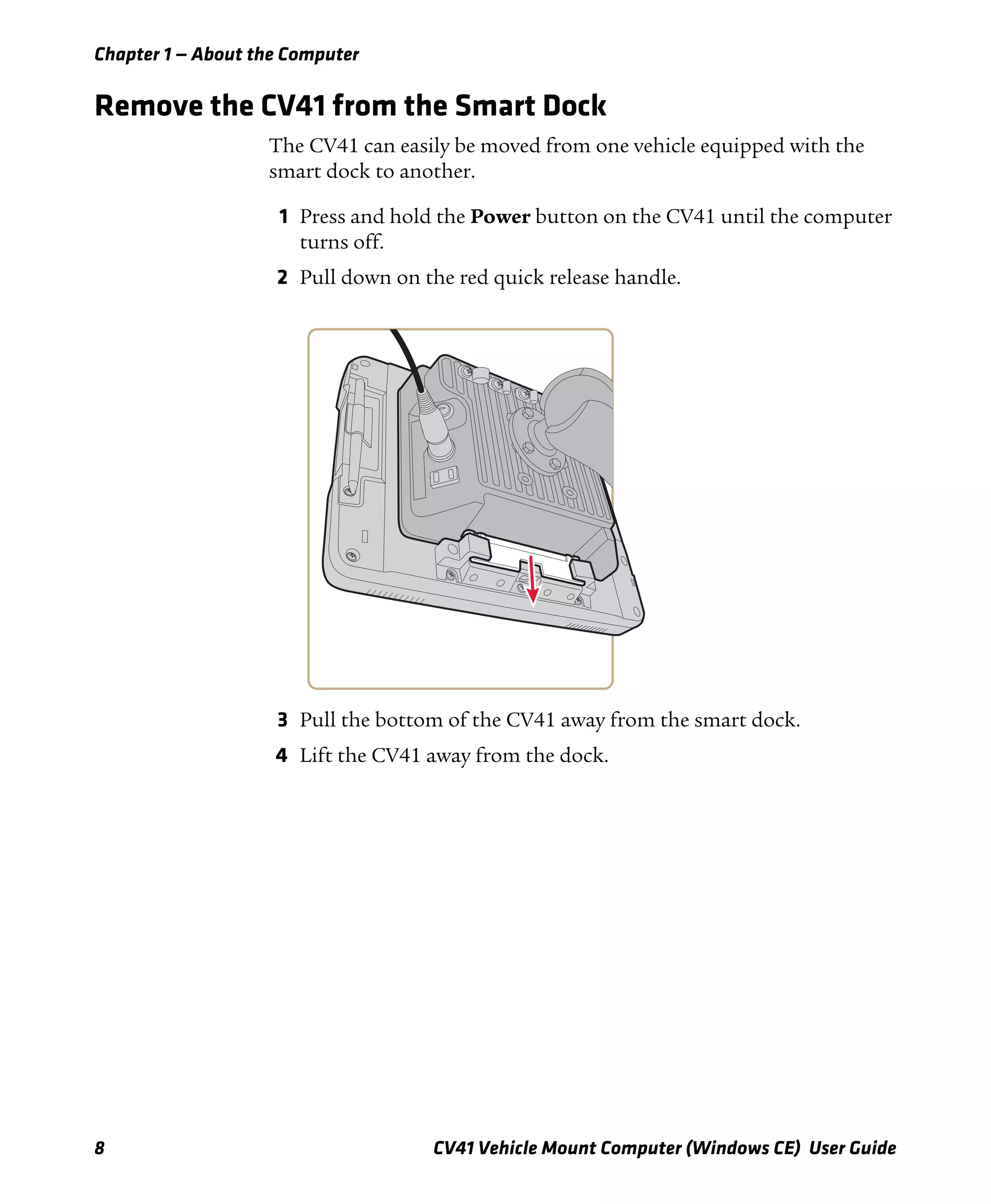
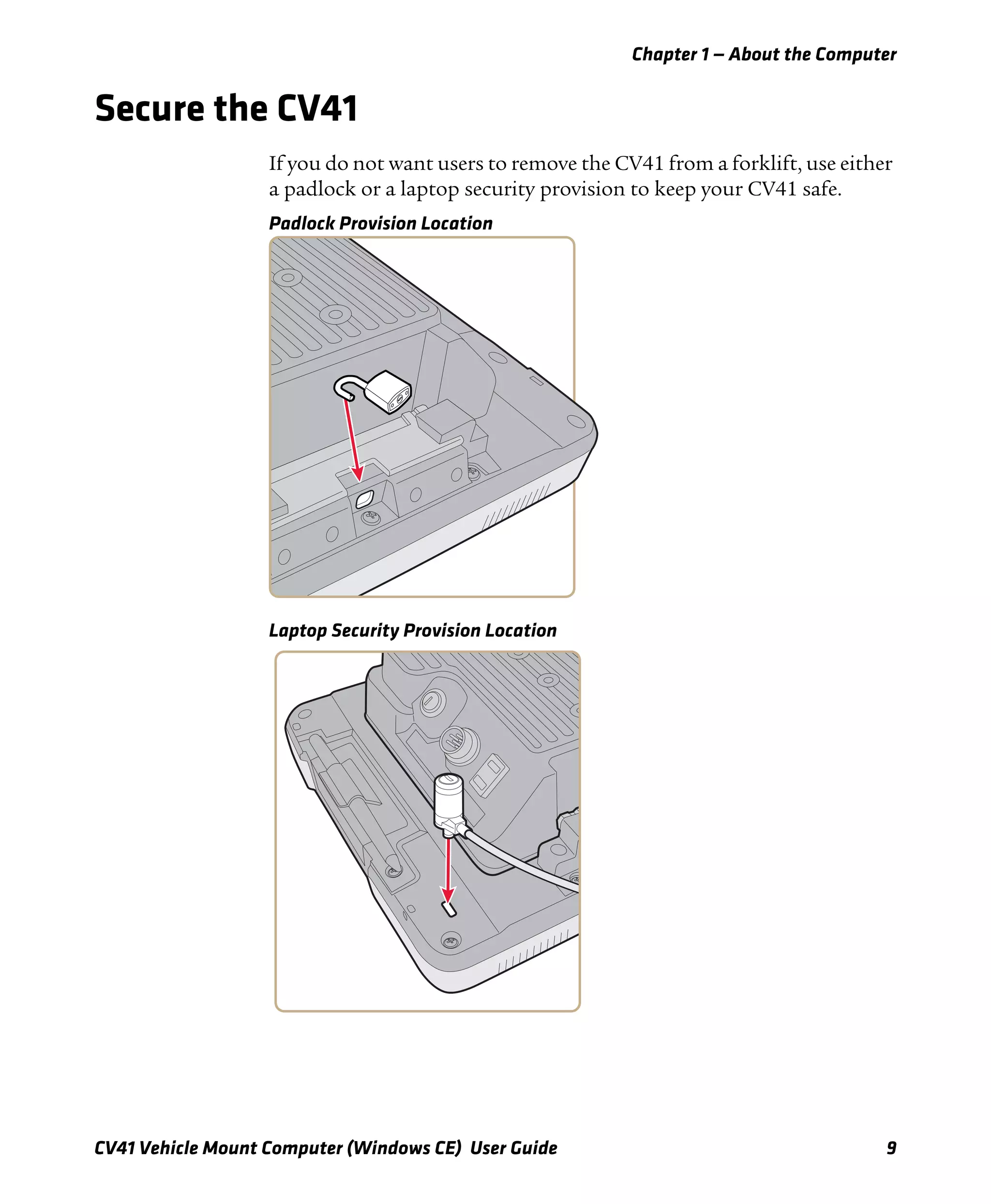
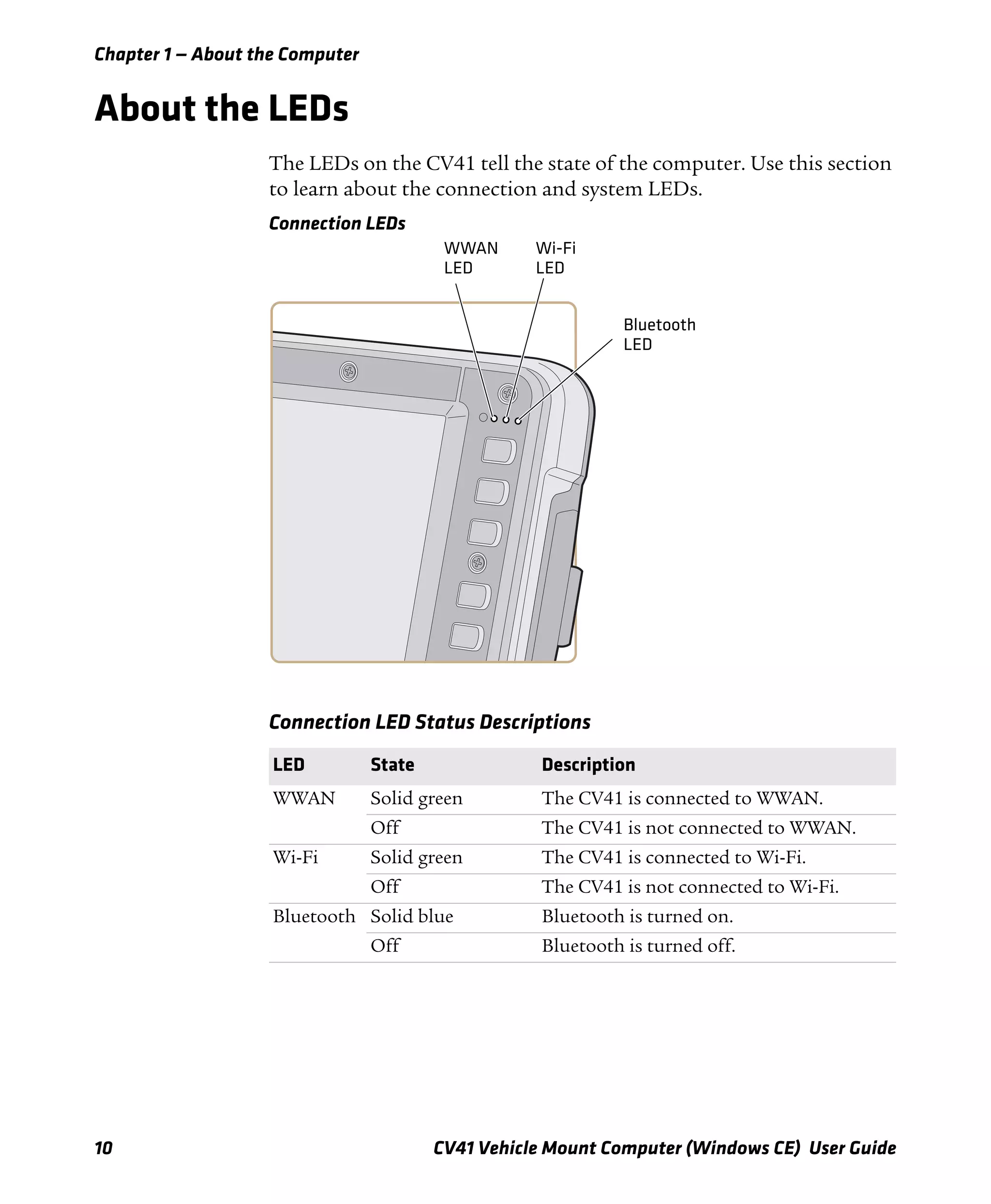
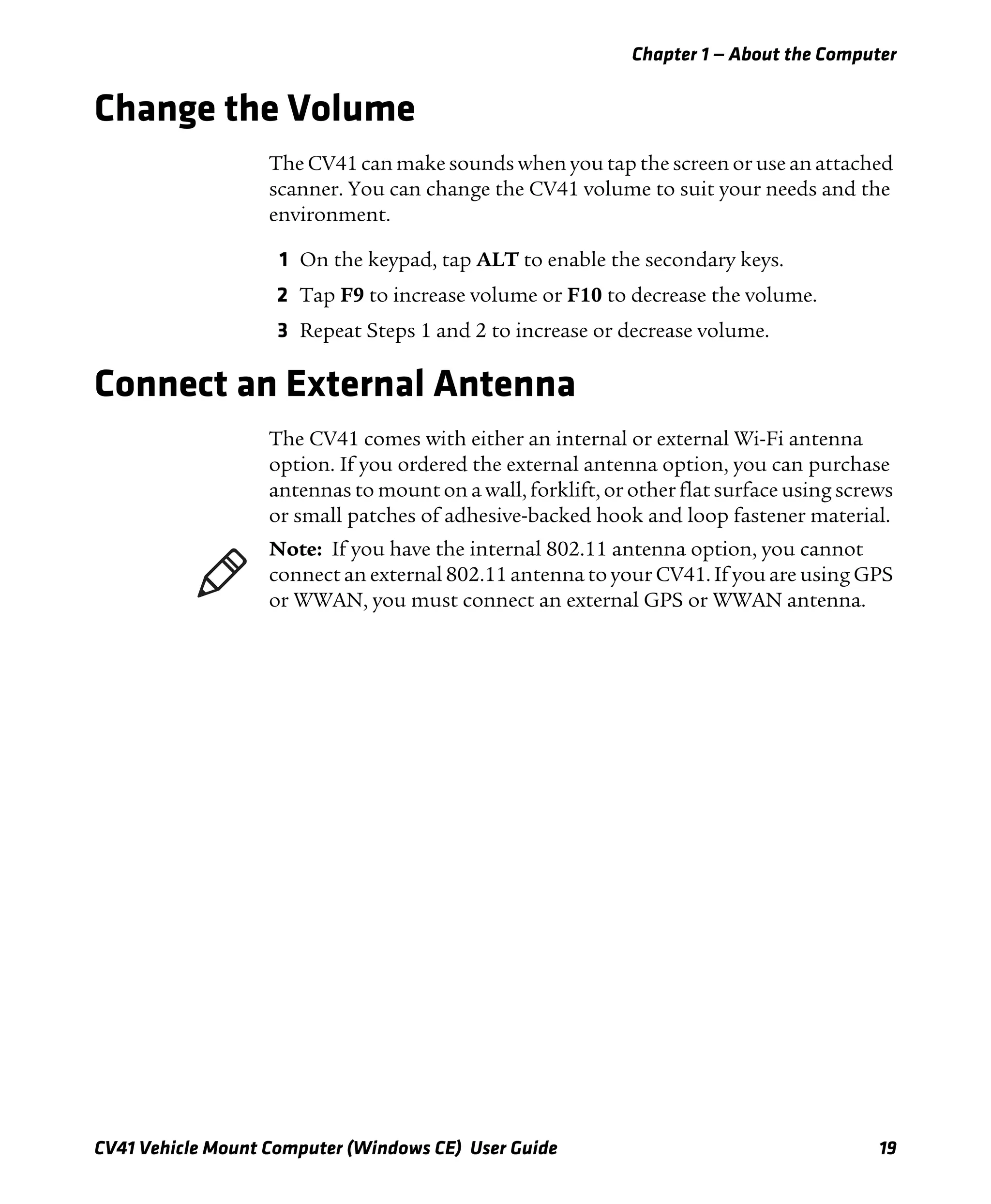
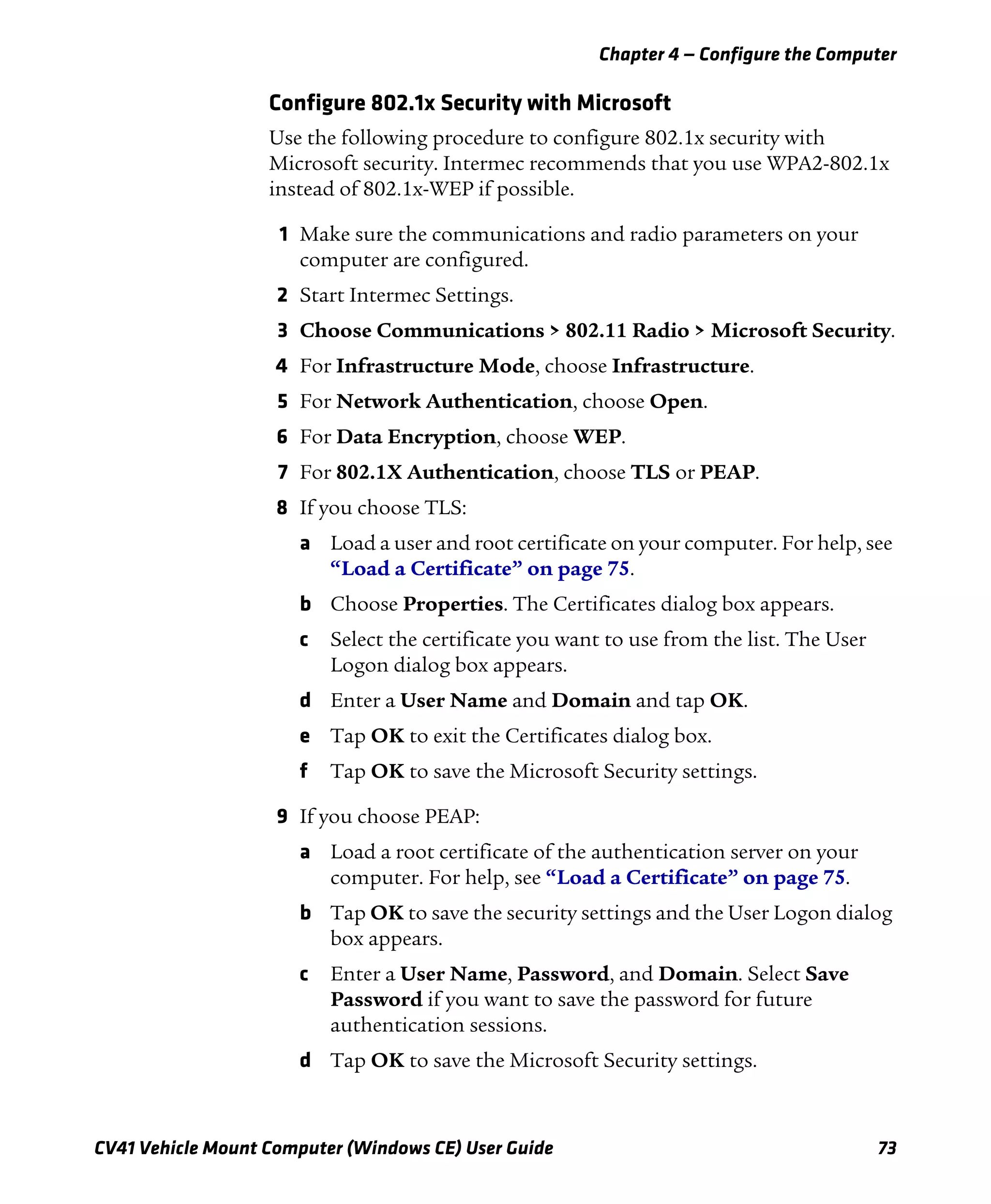
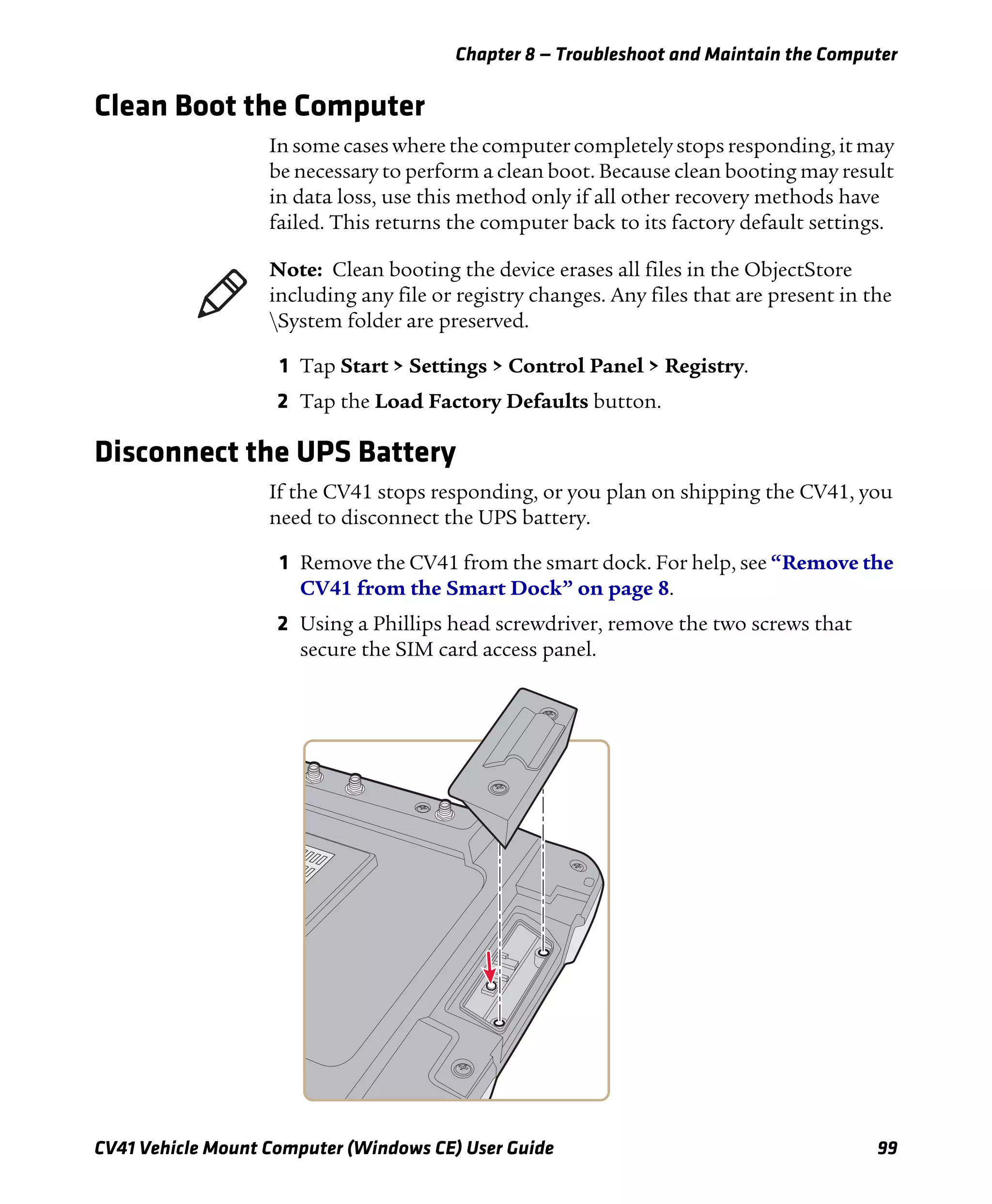
![Chapter 1 — About the Computer
22 CV41 Vehicle Mount Computer (Windows CE) User Guide
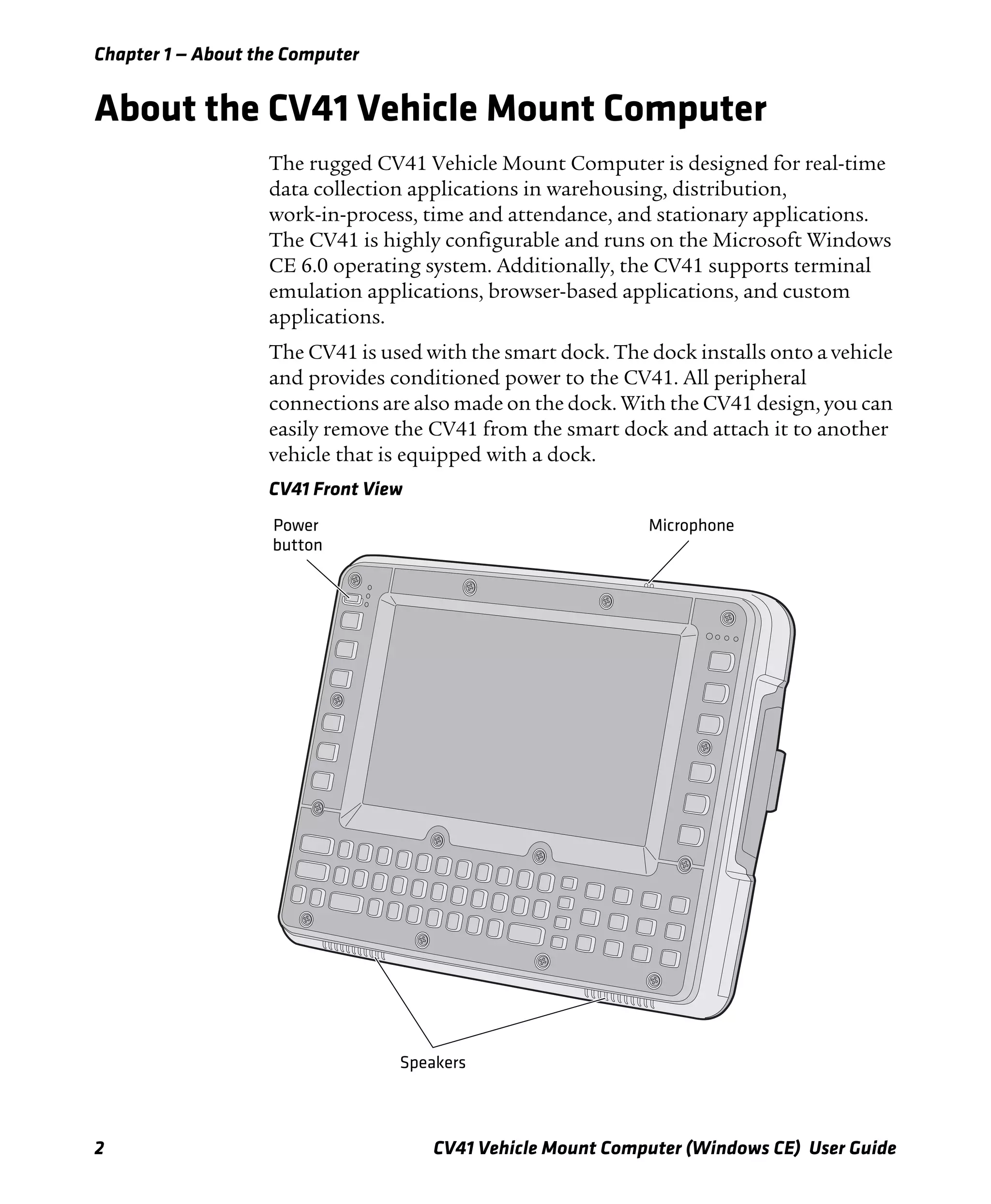
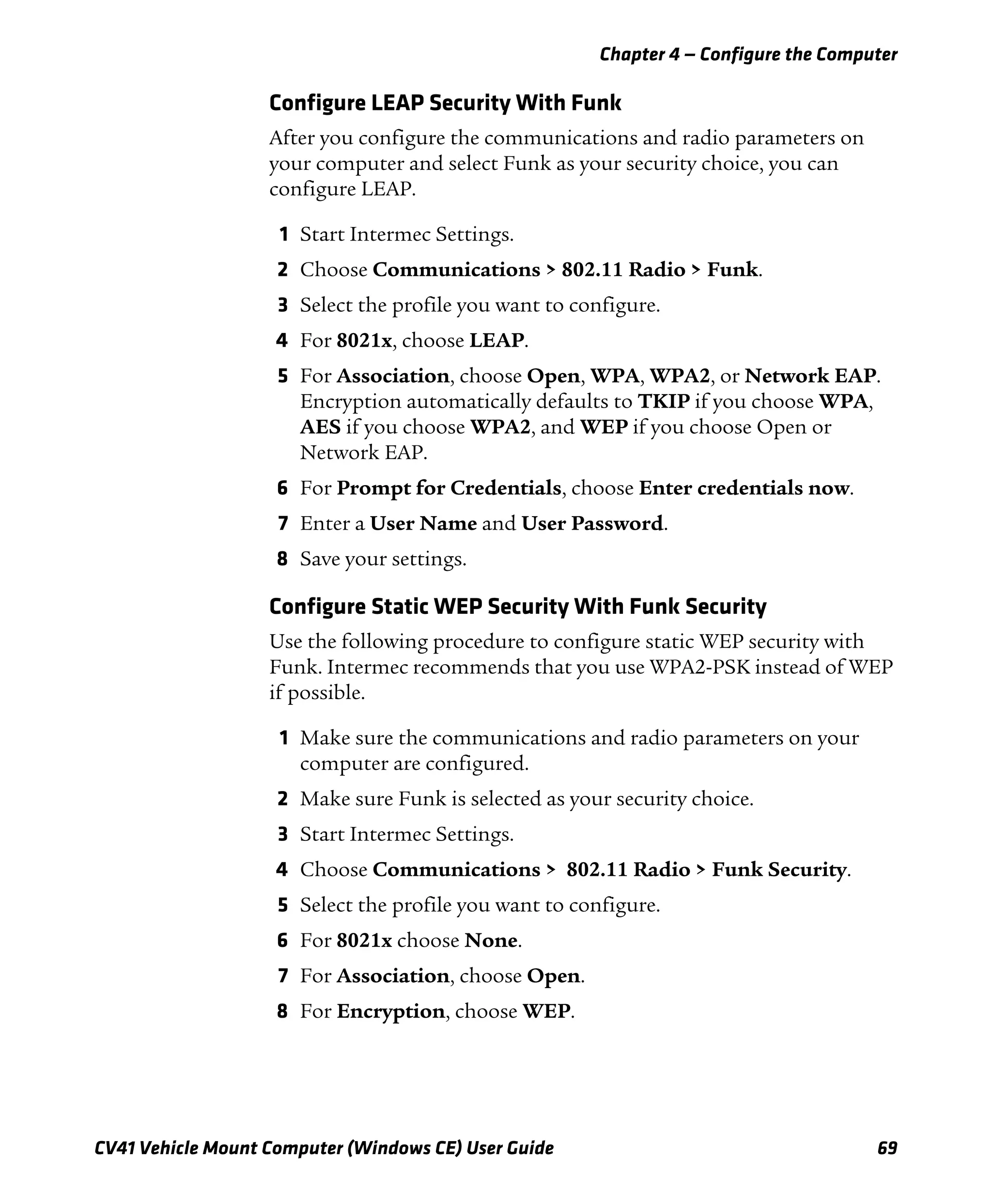
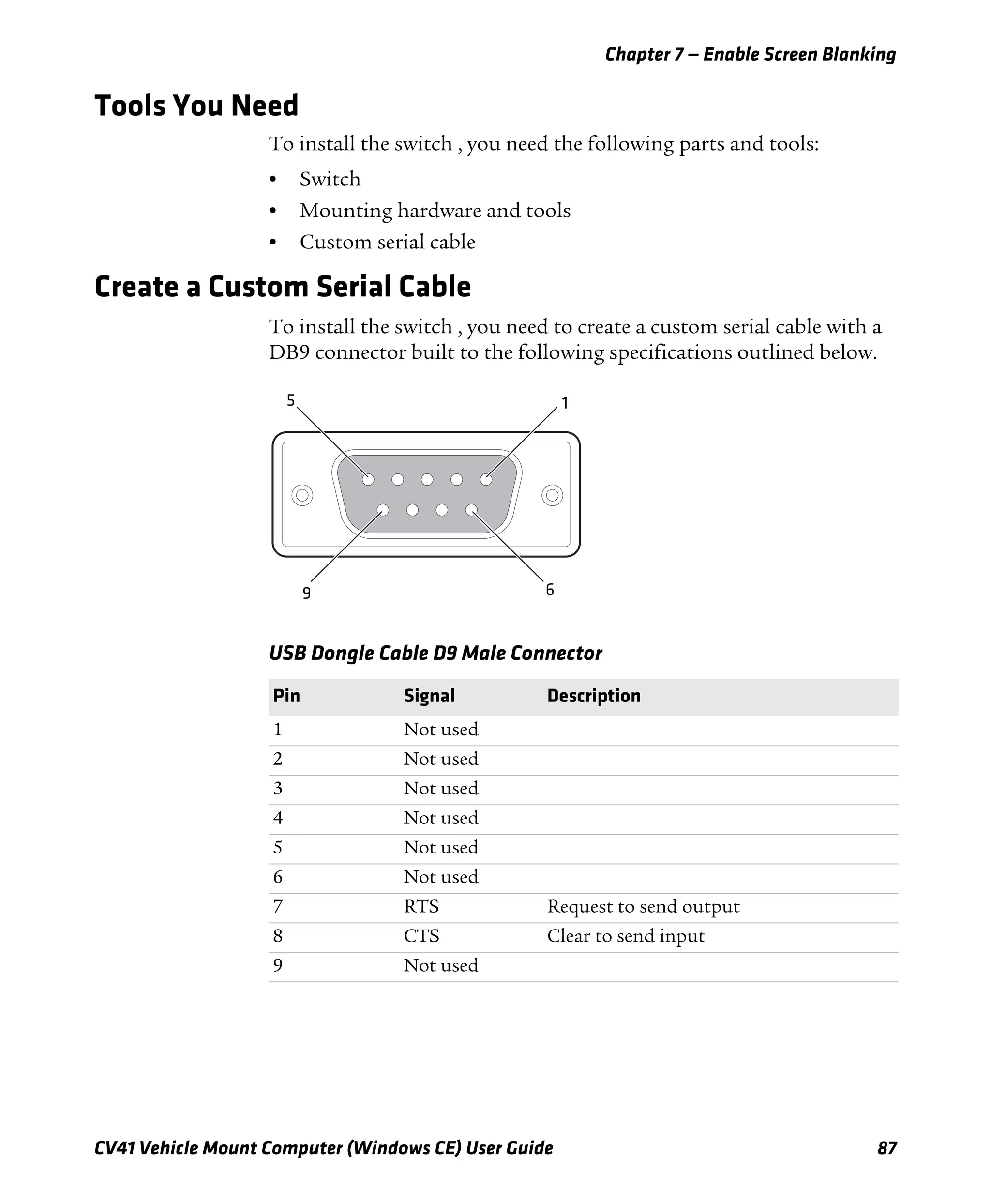
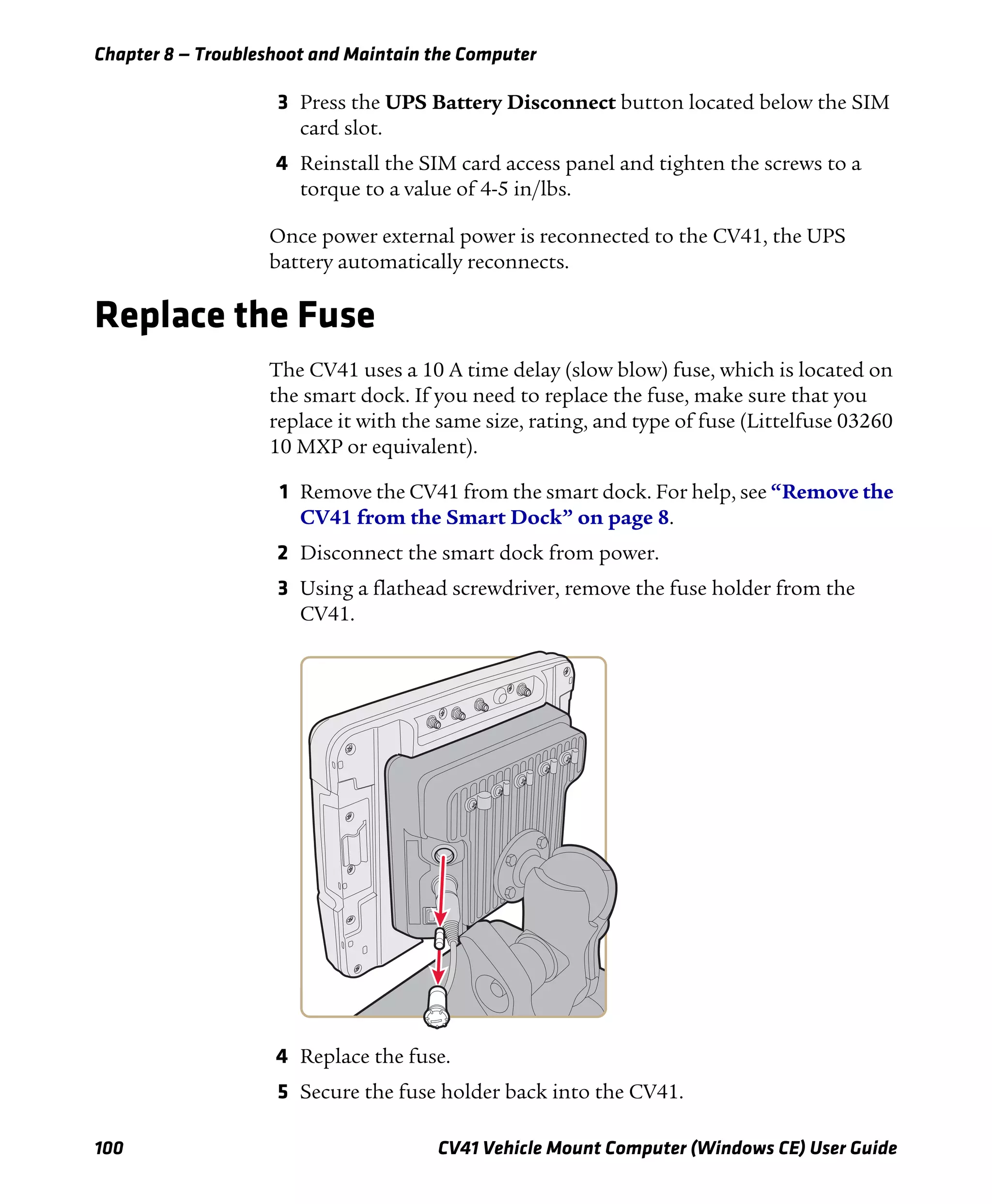
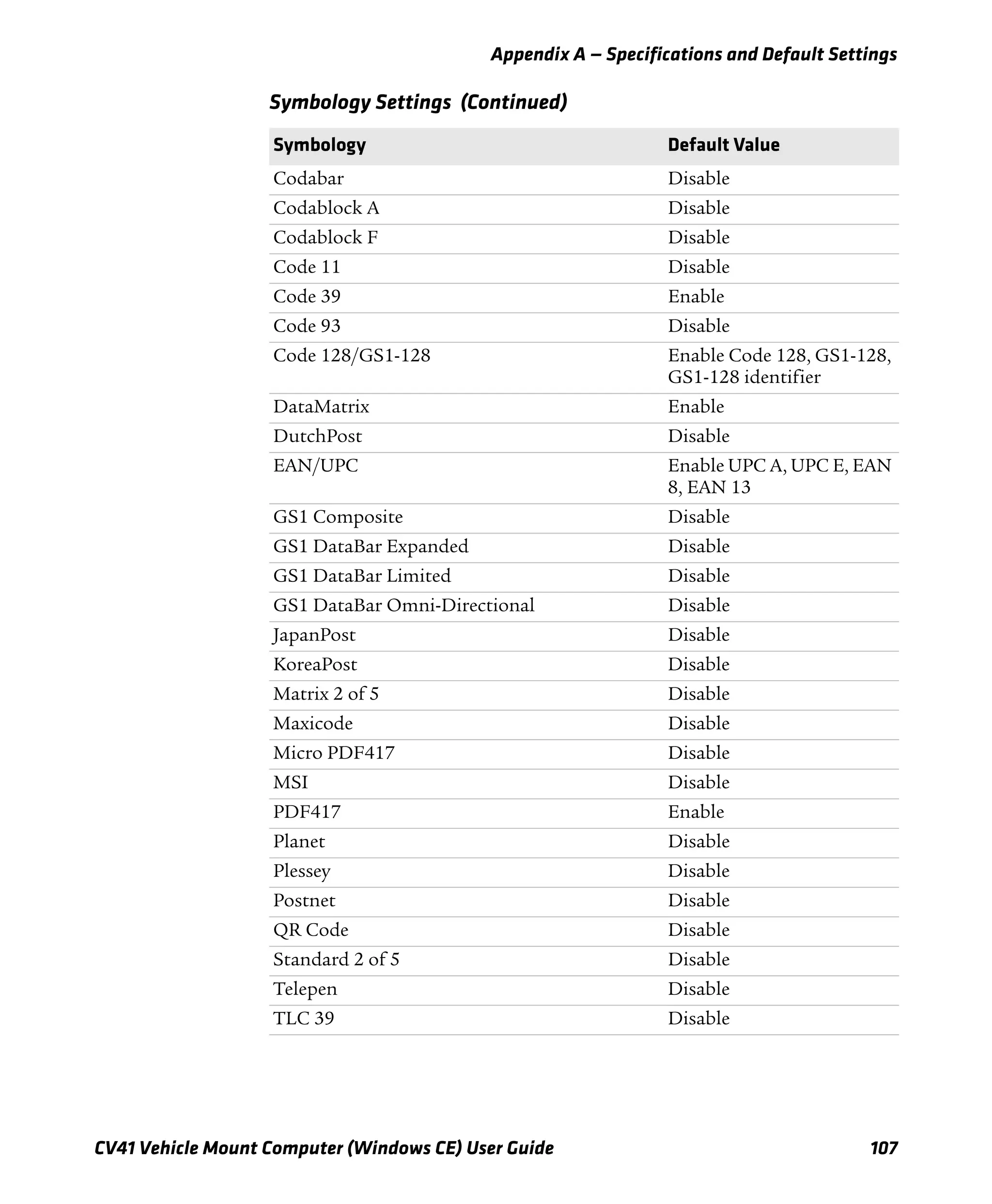
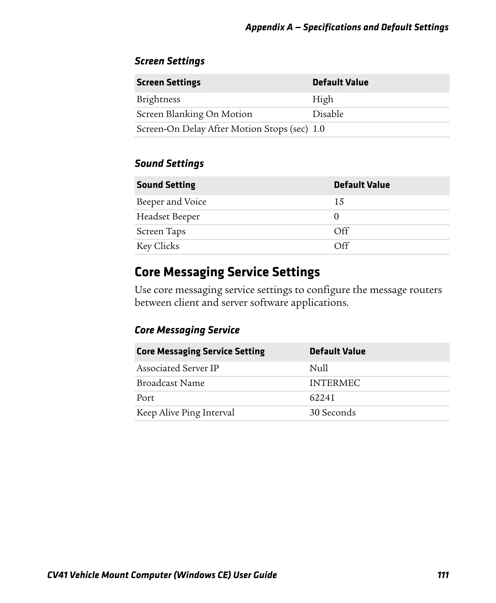
Use the Modifier Keys
The CV41 keypad provides modifier keys to let you access additional
characters, symbols, and functions printed on the keypad overlay.
Once you understand how to use the modifier keys and key sequences,
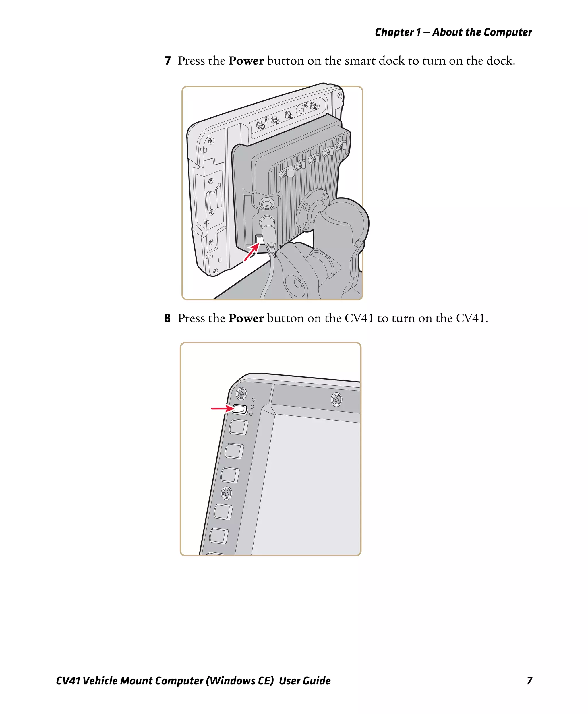
you can access all of the additional features printed on the keypad
overlay.
There are three modifier keys: the orange ( b ) key, the green ( Alt ) key,
and the Control ( Ctrl ) key.
Capitalize Characters
You can capitalize characters individually, or you can type all capital
letters by enabling Caps Lock.
To capitalize a single character:
• Press the ] key. The Shift key LED flashes to show that the Shift
key is enabled for one key press.
To enable Caps lock:
• Press the b key, and then the ] key. The Shift key LED lights up
green to show that the CV41 is in Caps Lock mode.
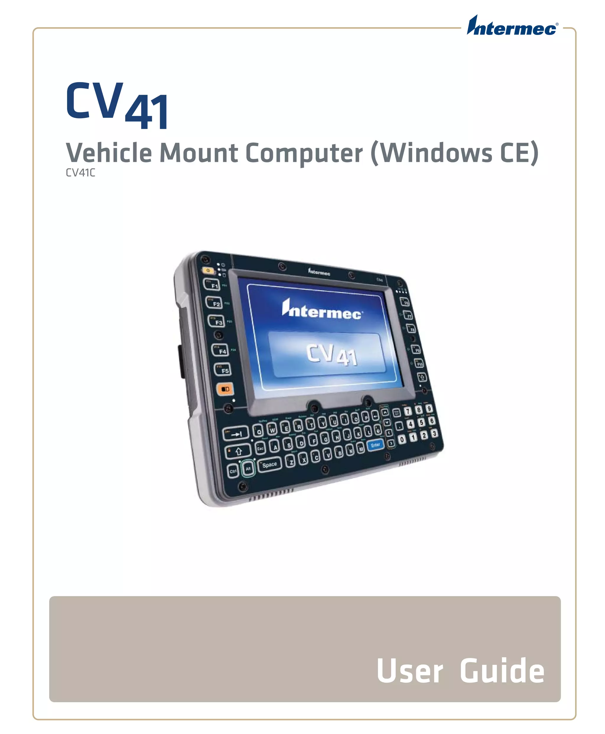
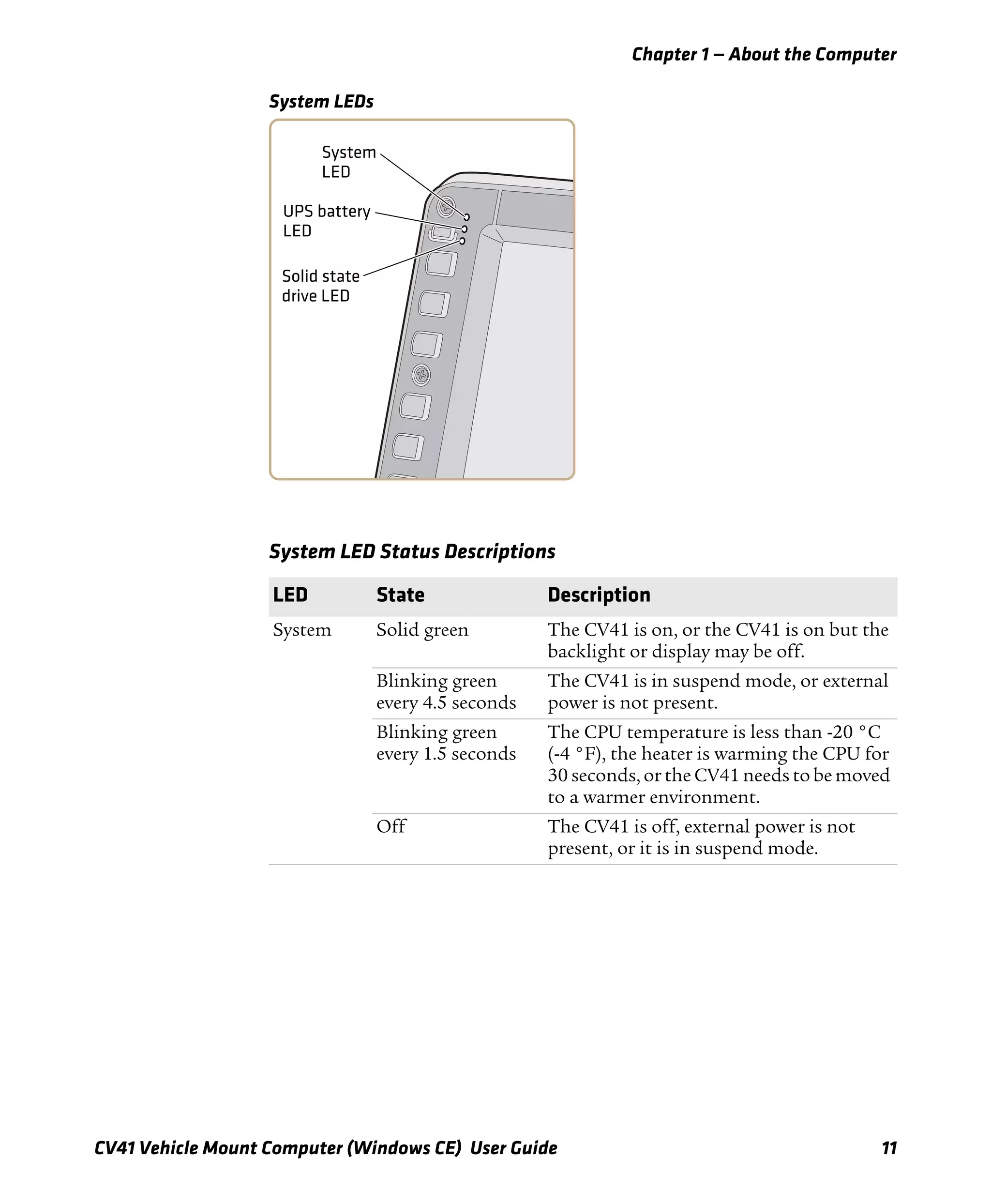
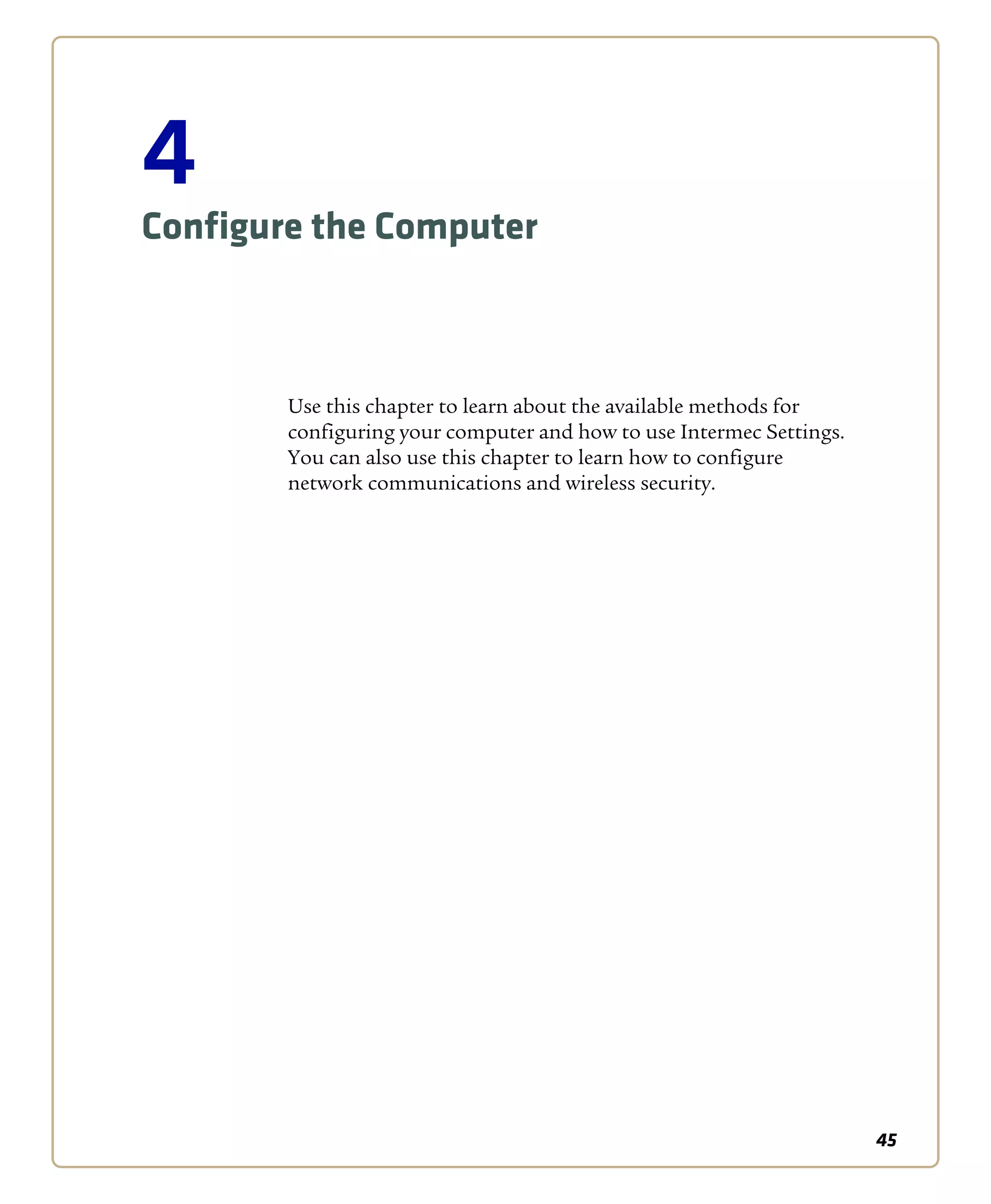
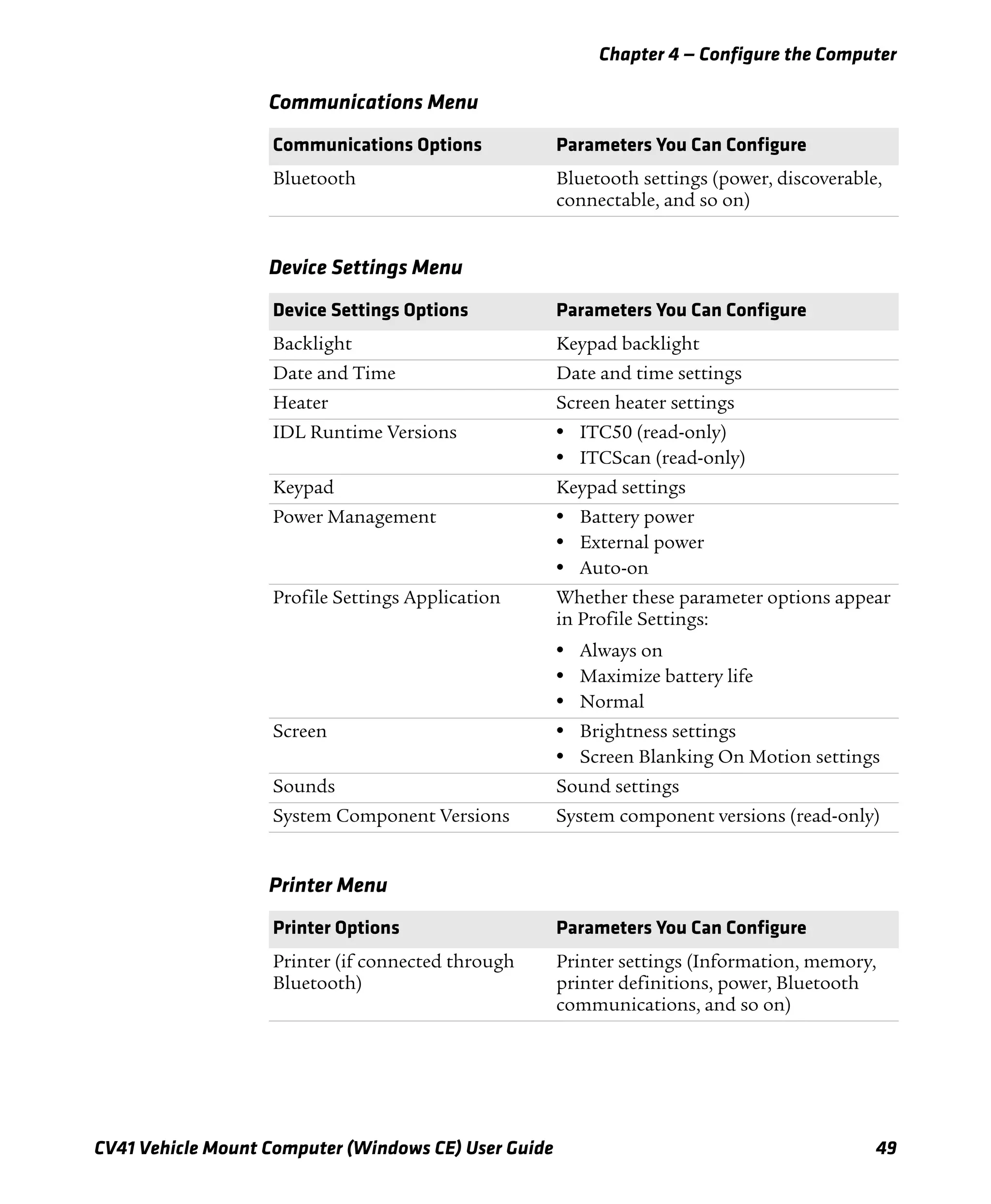
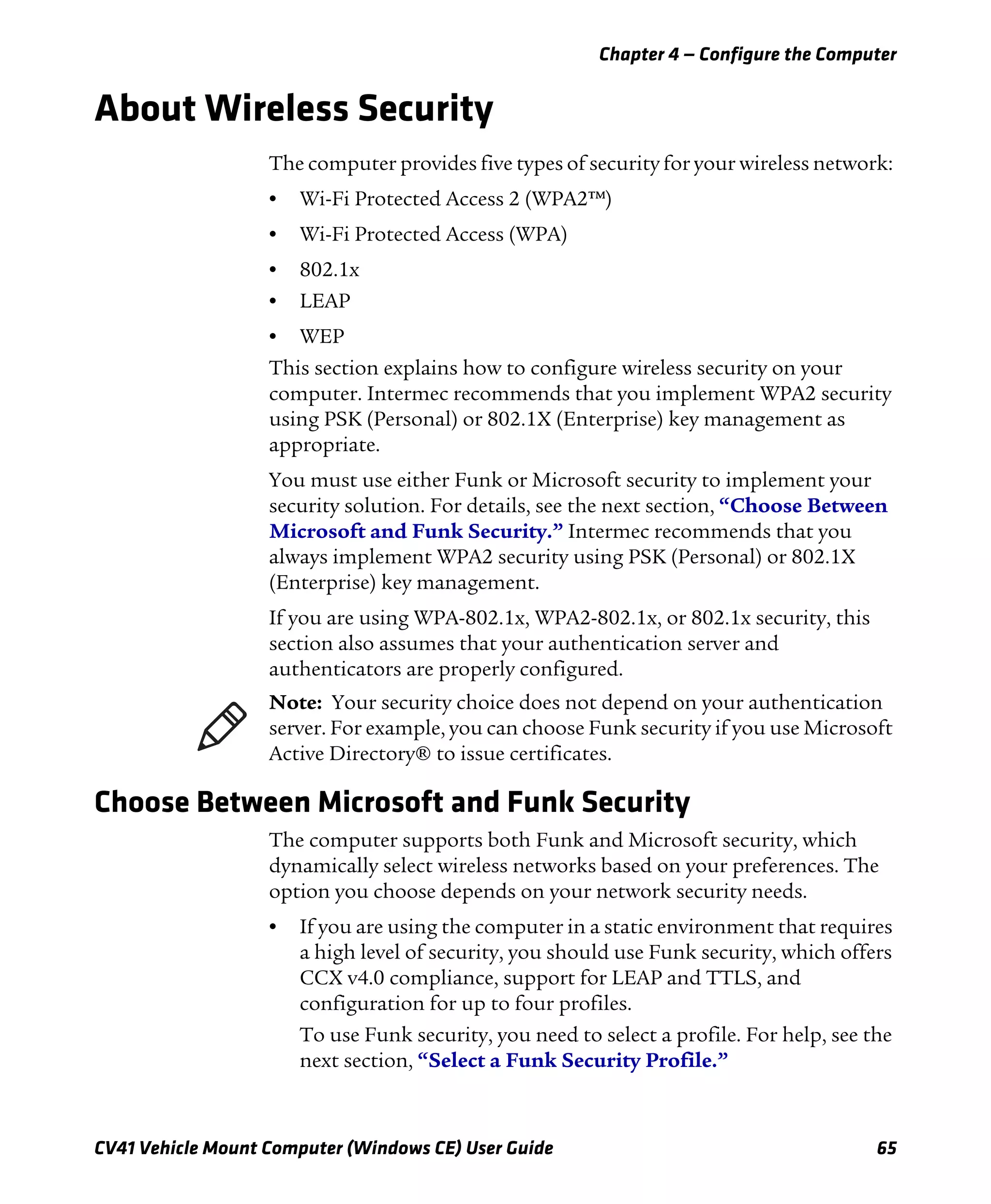
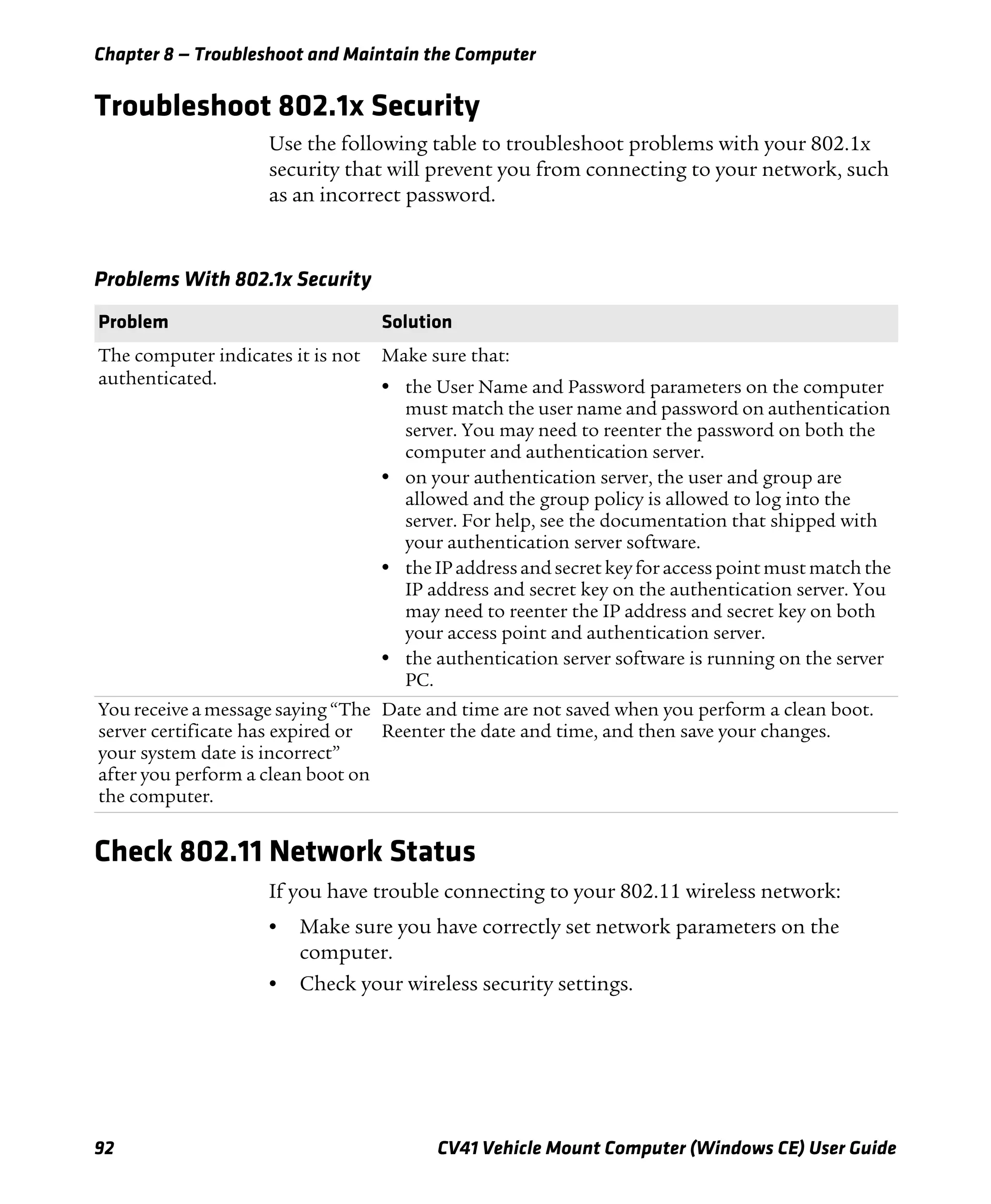
Use the Color-Coded Keys
You want to: Press: Example:
Use an orange character or
function printed above a key.
b key (LED turns on) and then
the key with the character or
function printed above it (LED
turns off).
Press b and then ¡ to select the
F11 function.
Use a green character or
function printed above the
key.
Alt key (LED turns on) and then
the key with the character or
function printed above it (LED
turns off).
Press Alt and then P to select
the Print function.
Enable the Control modifier
key.
Ctrl key (LED turns on) and then
the key with the character or
function printed above it (LED
turns off)](https://image.slidesharecdn.com/manualdousuariowindowsce-160429180048/75/Manual-CV41-36-2048.jpg)
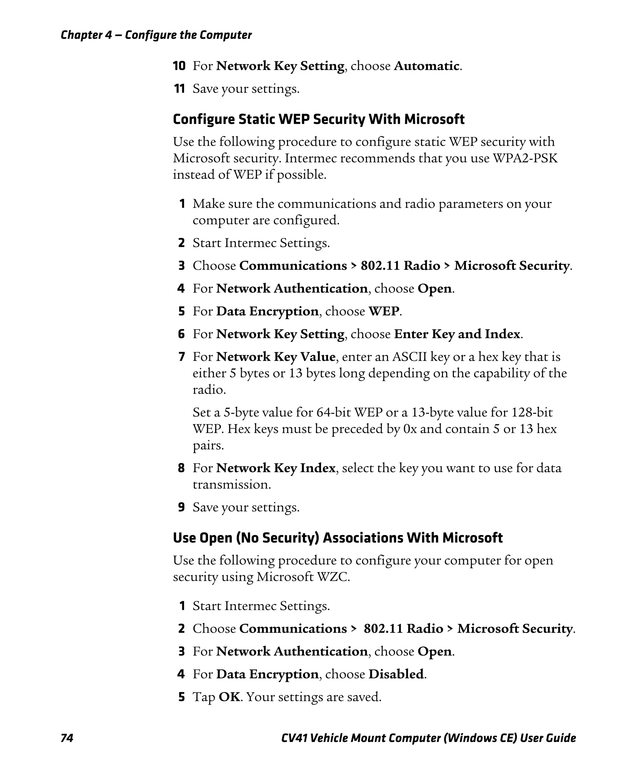
![Chapter 1 — About the Computer
CV41 Vehicle Mount Computer (Windows CE) User Guide 23
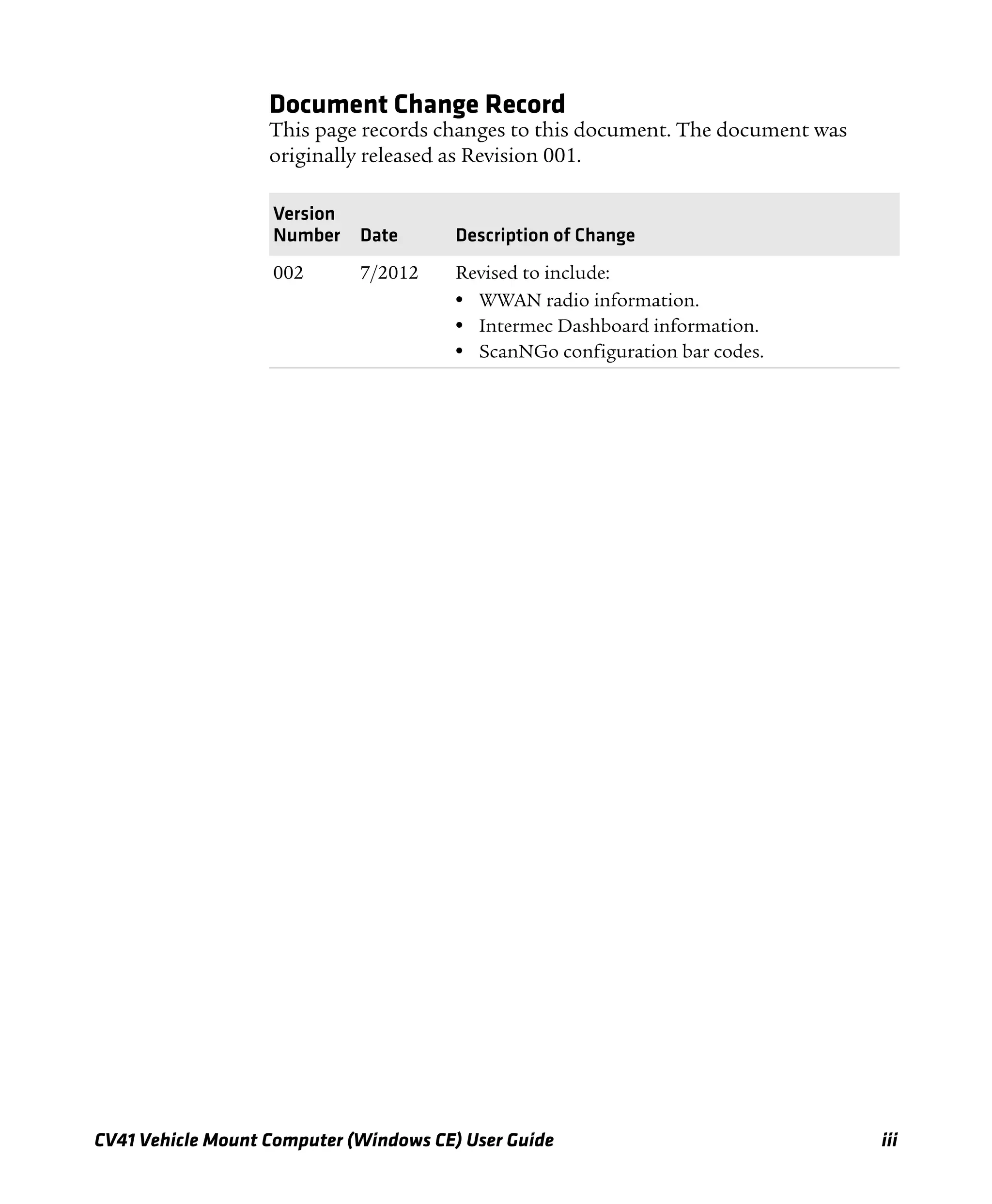
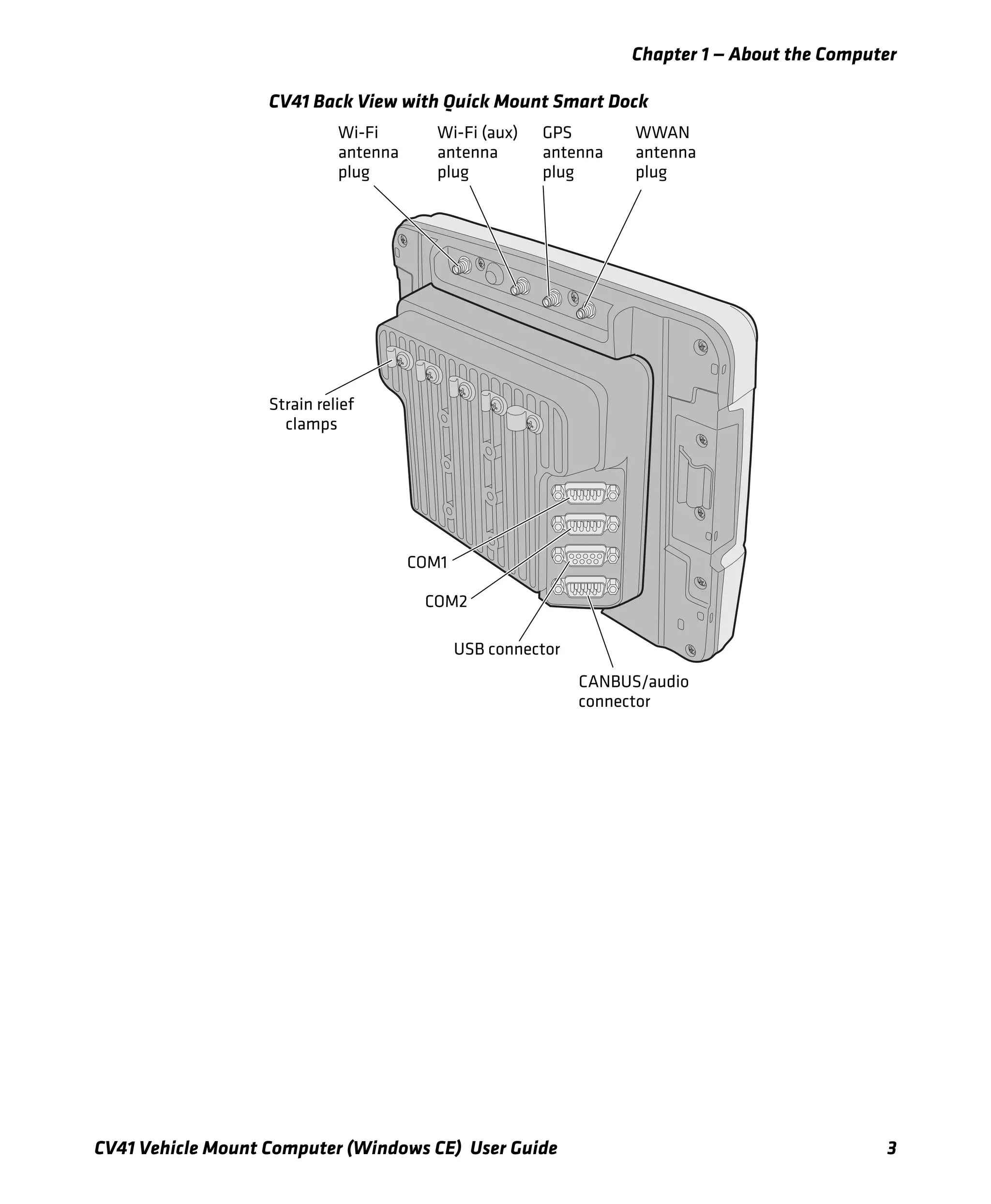
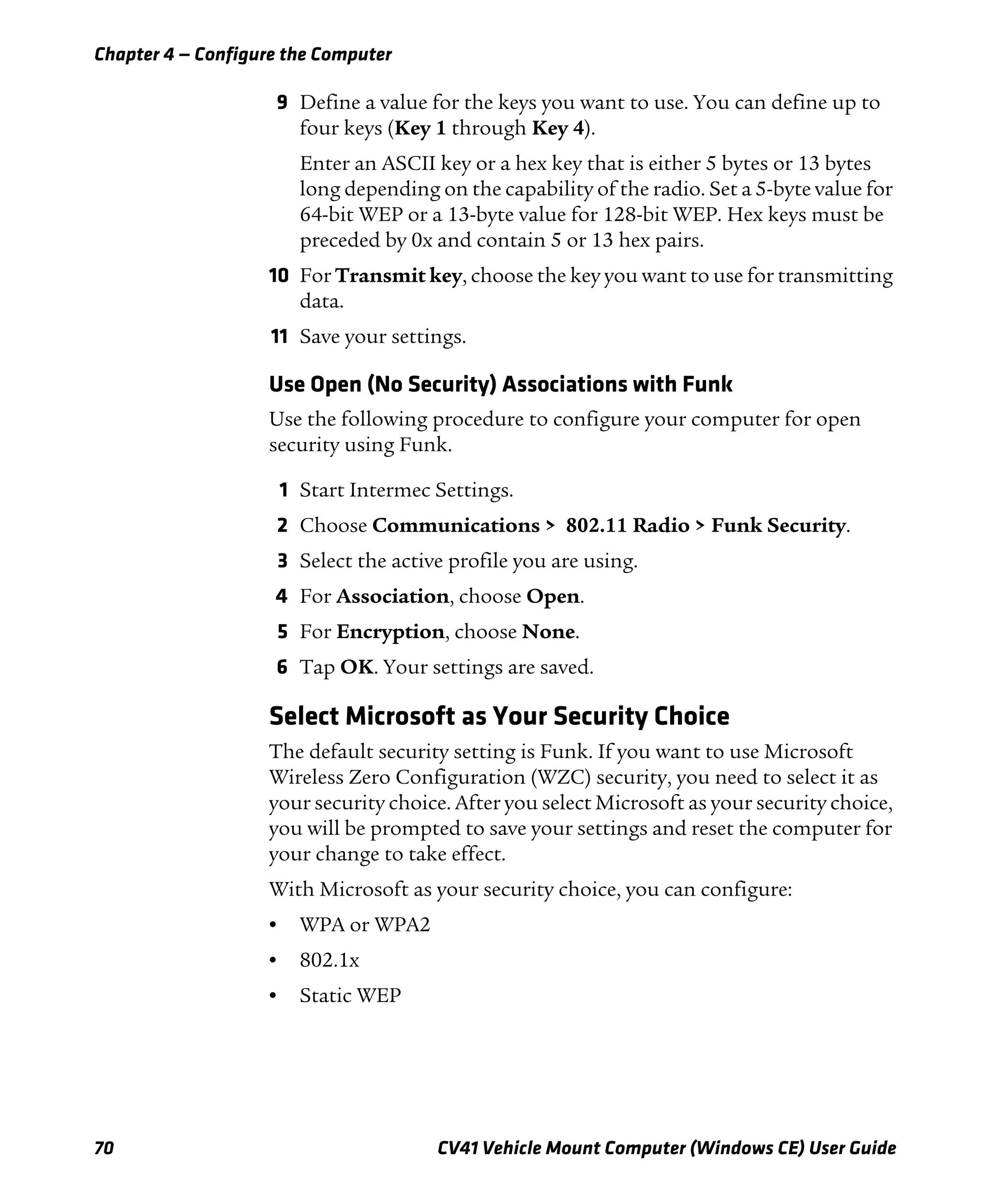
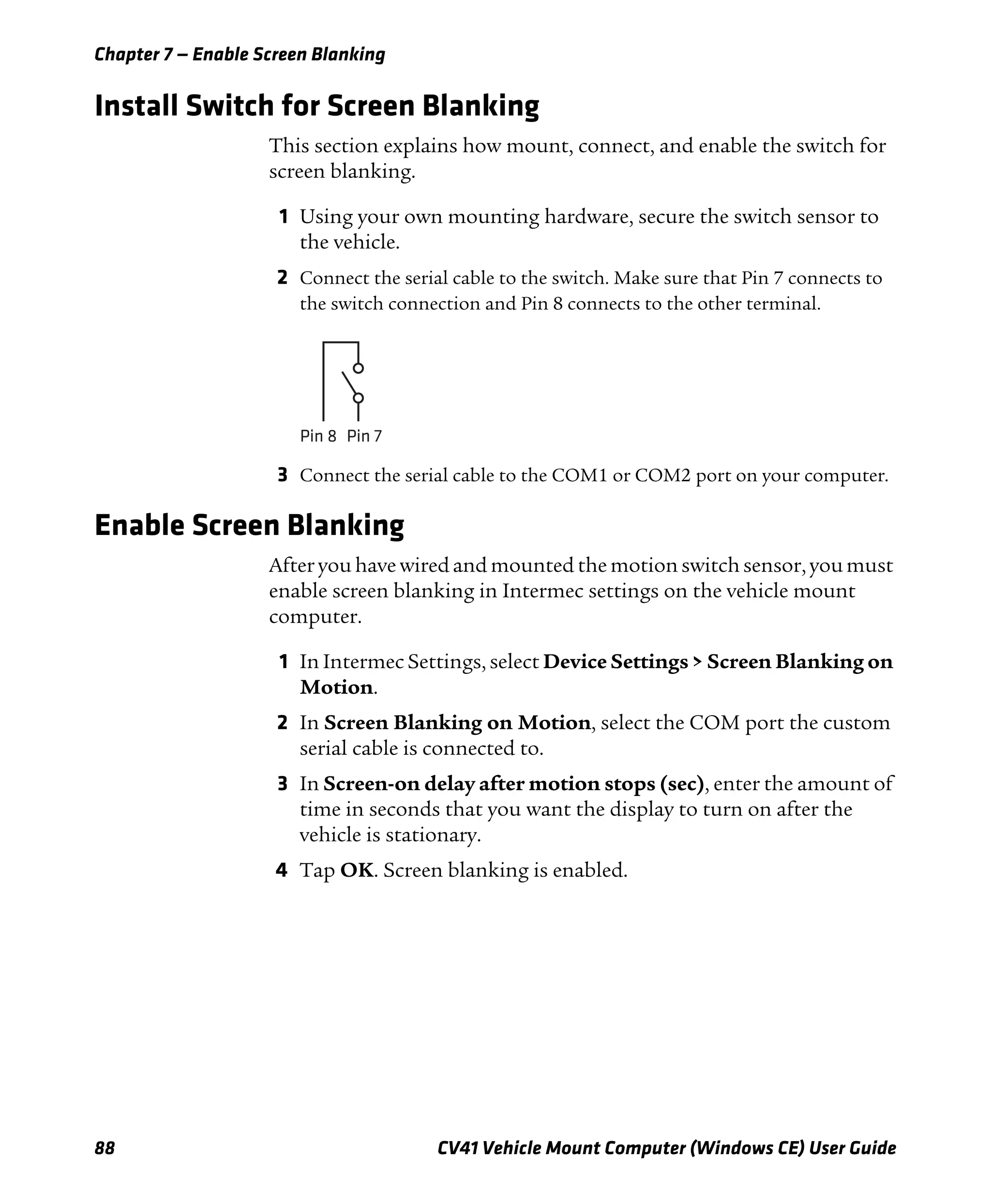
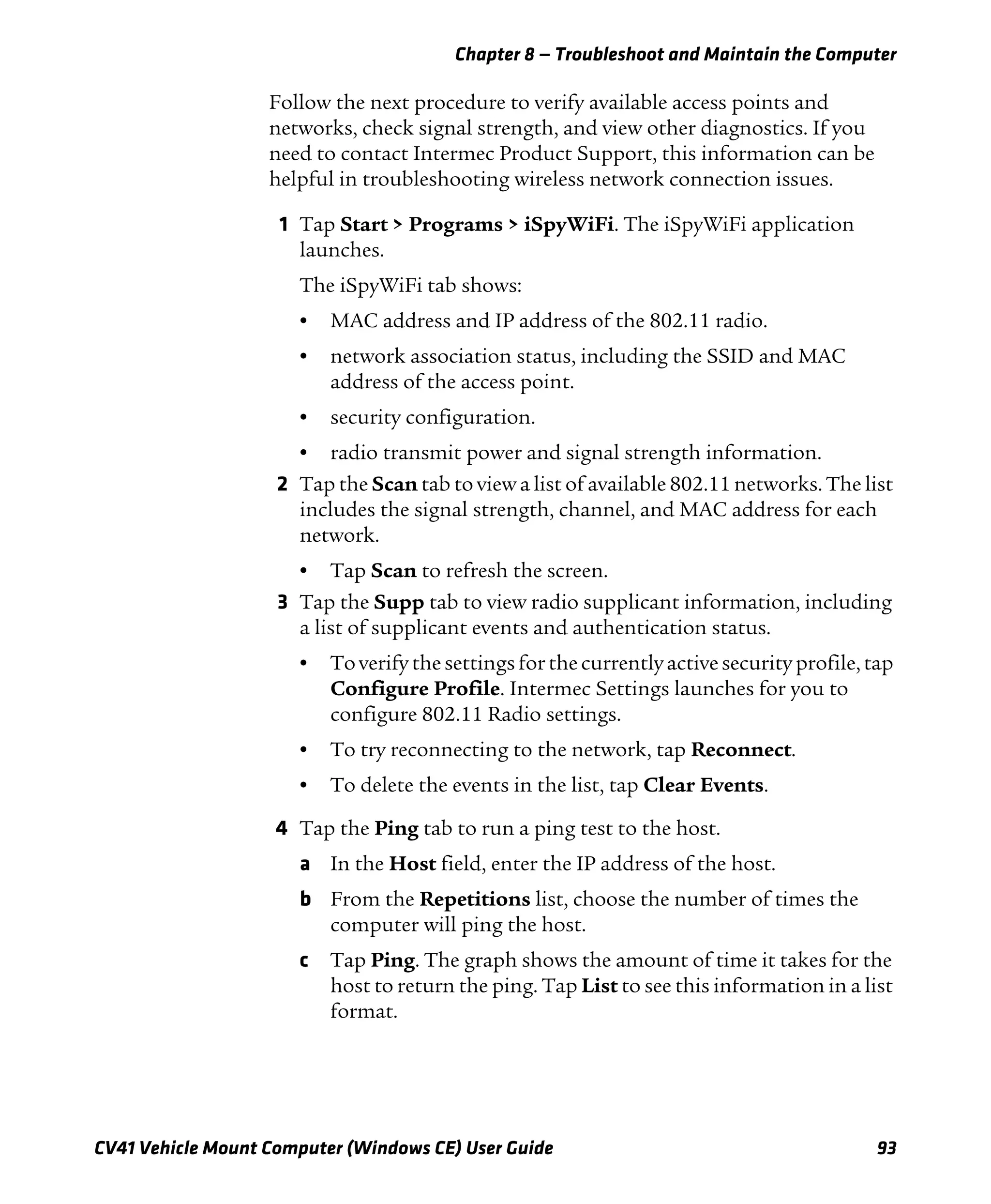
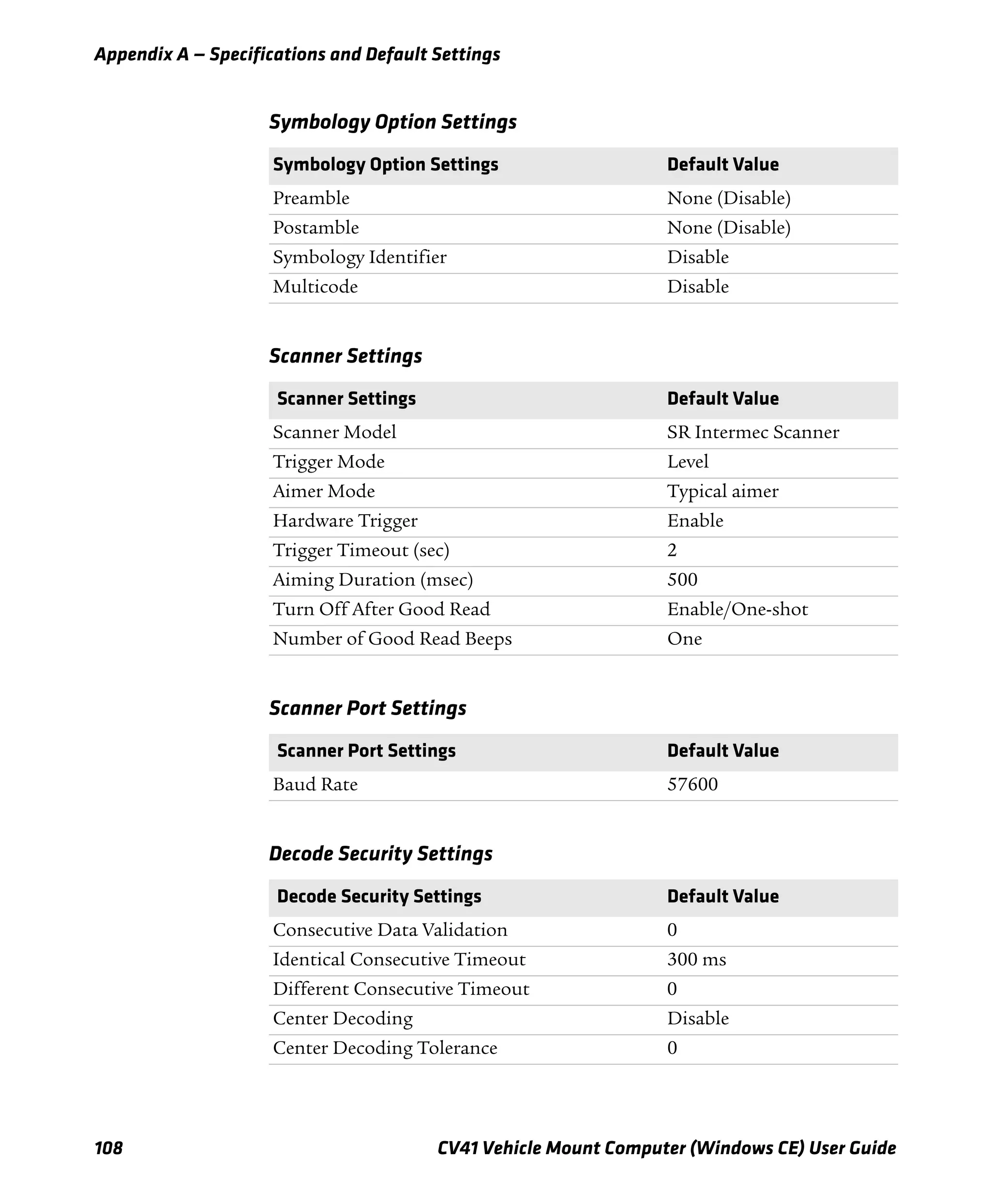
To disable Caps Lock:
• When Caps Lock is enabled, press the b key, and then the ] key.
The Shift key LED turns off to show that Caps Lock has been
disabled.
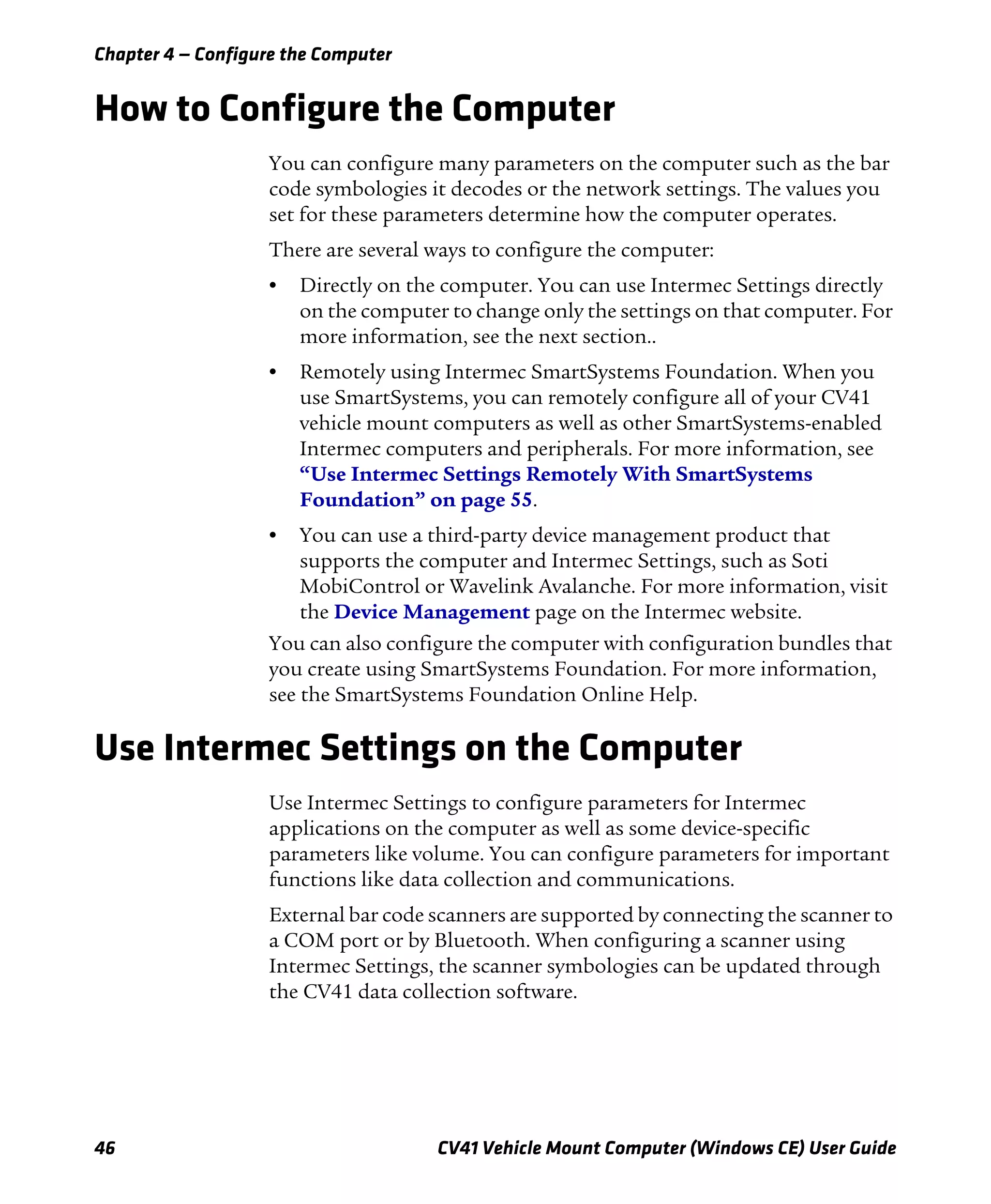
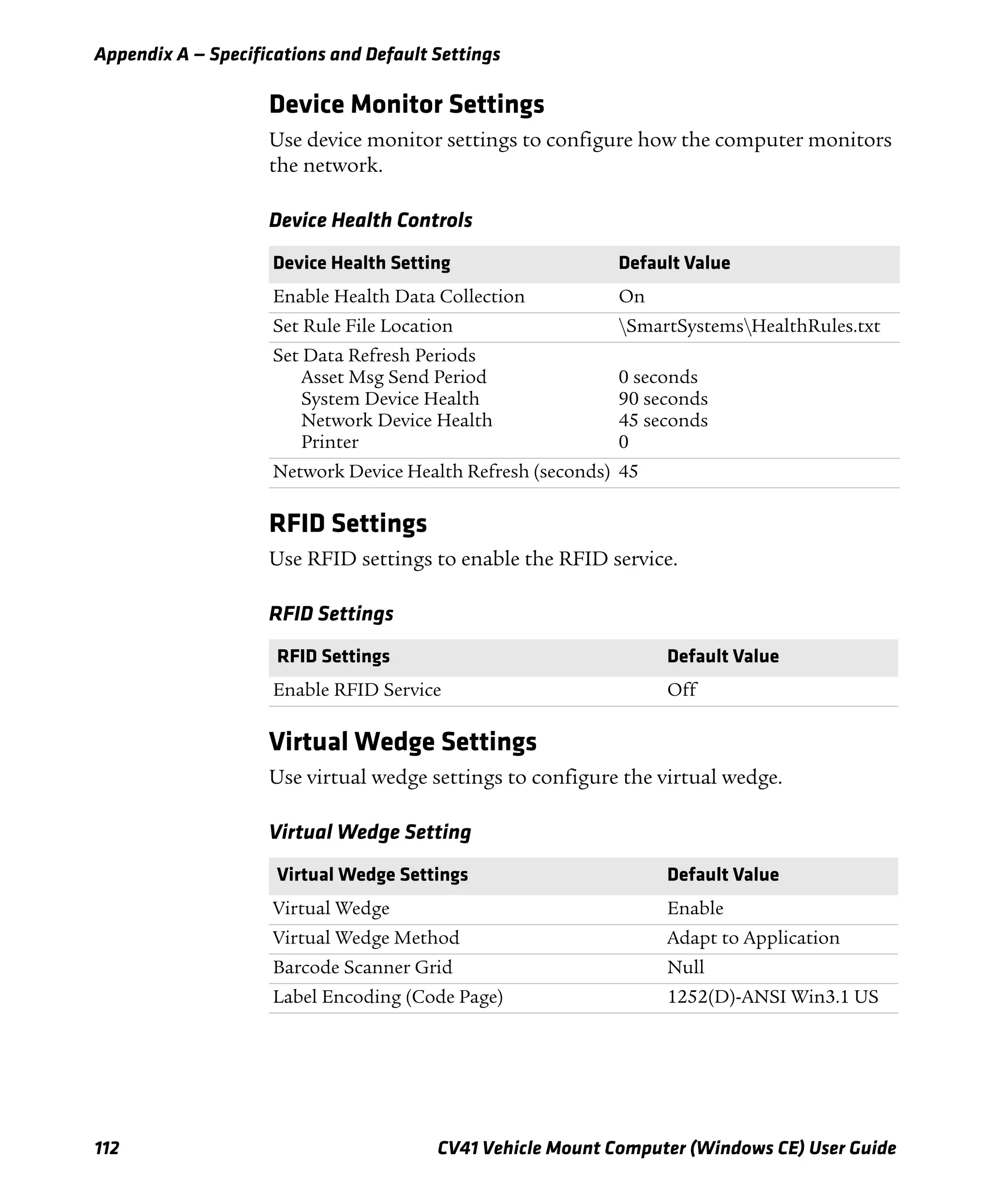
Enable or Disable the Keypad Backlight
The computer has a keypad backlight for low light conditions. By
default, the keypad backlight is enabled. Disable the keypad to
conserve power.
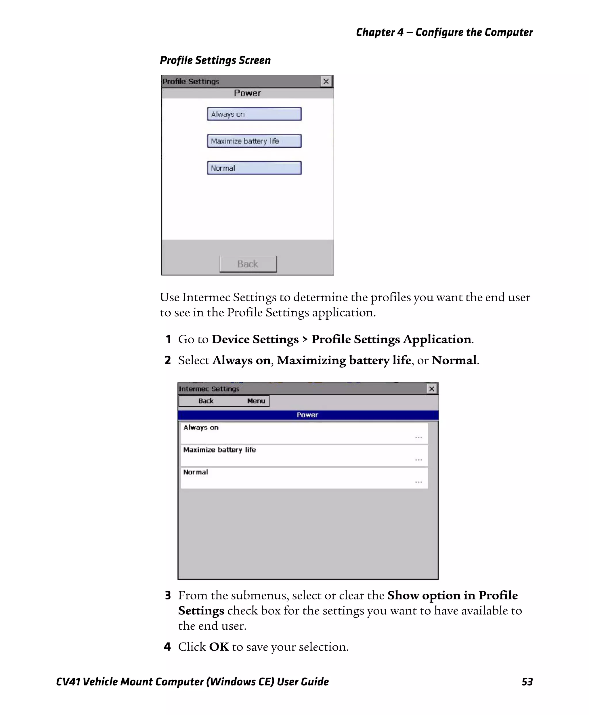
1 Tap Start > Settings > Control Panel > Intermec Settings. The
Intermec Settings screen appears.
2 Tap Device Settings > Backlight > Keypad Backlight. The
Keypad Backlight screen appears.
3 Clear the check box to disable the backlight, and select the check
box to enable it.
4 Tap OK to save your changes.](https://image.slidesharecdn.com/manualdousuariowindowsce-160429180048/75/Manual-CV41-37-2048.jpg)


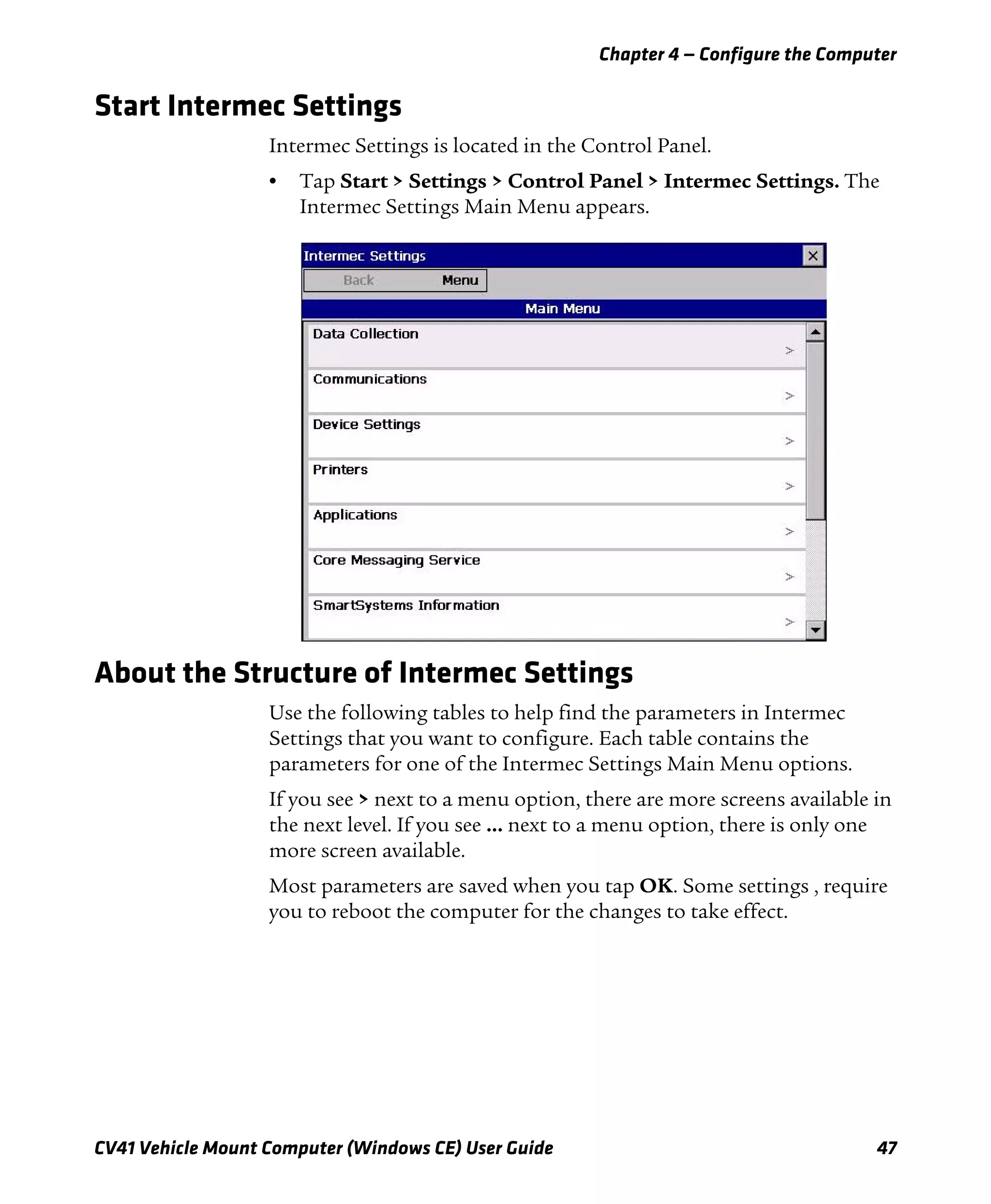
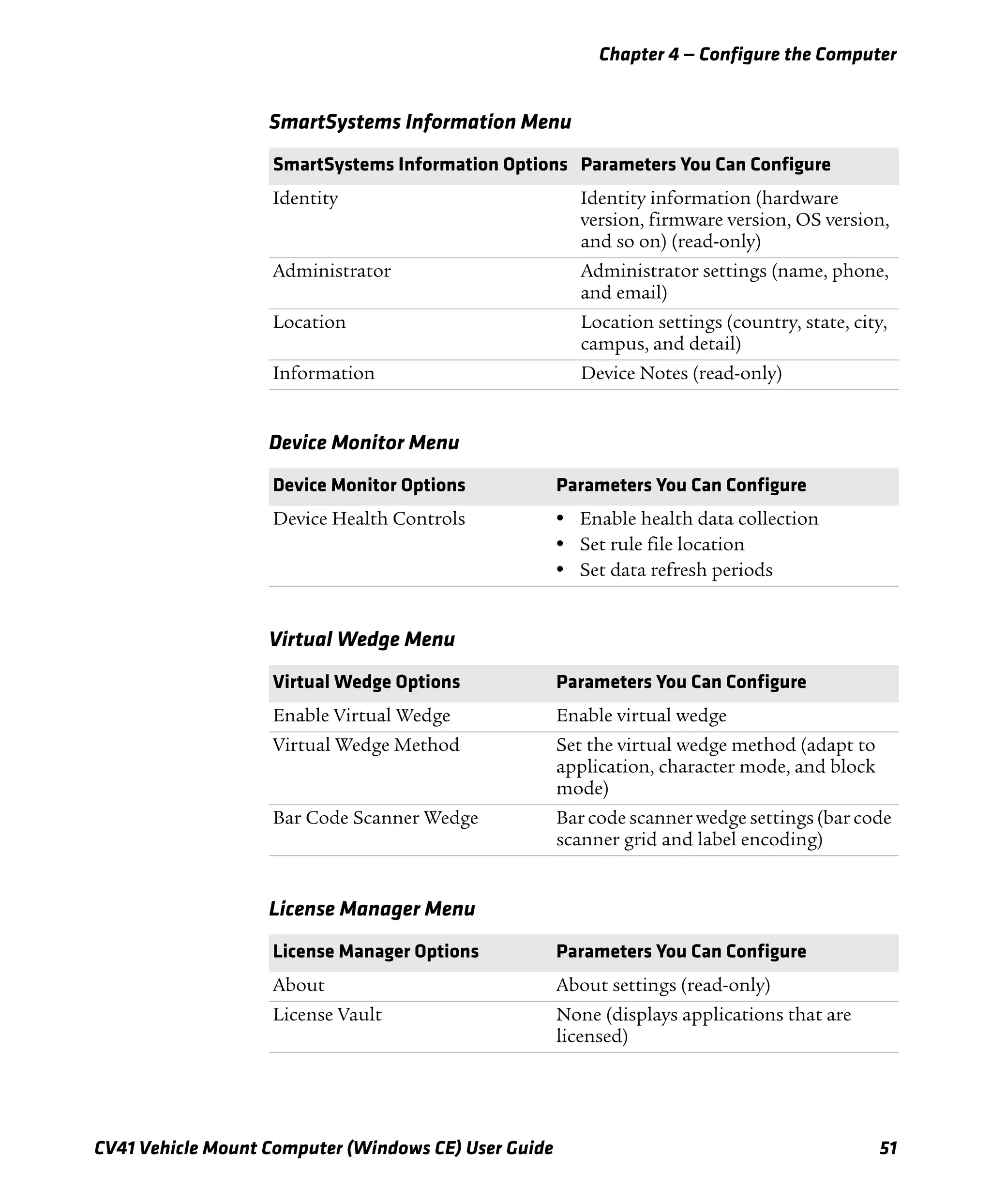
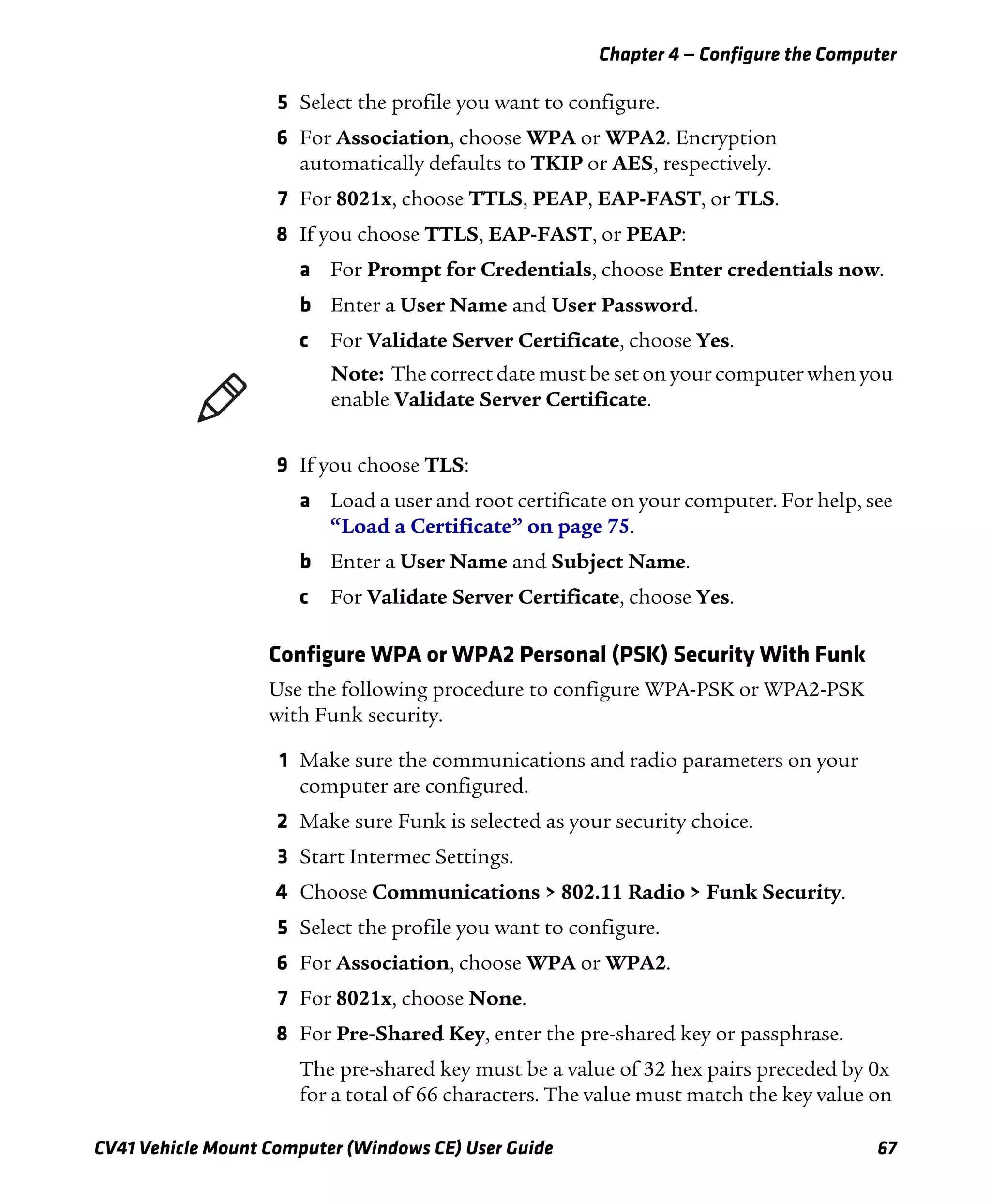
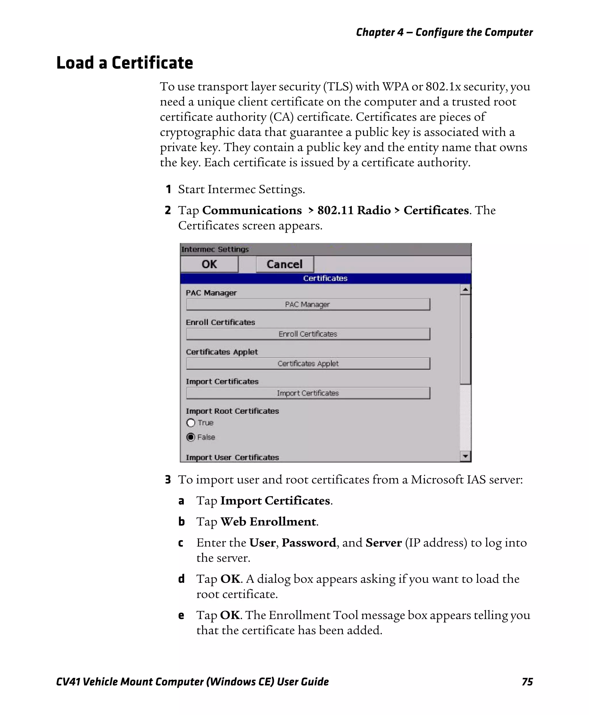


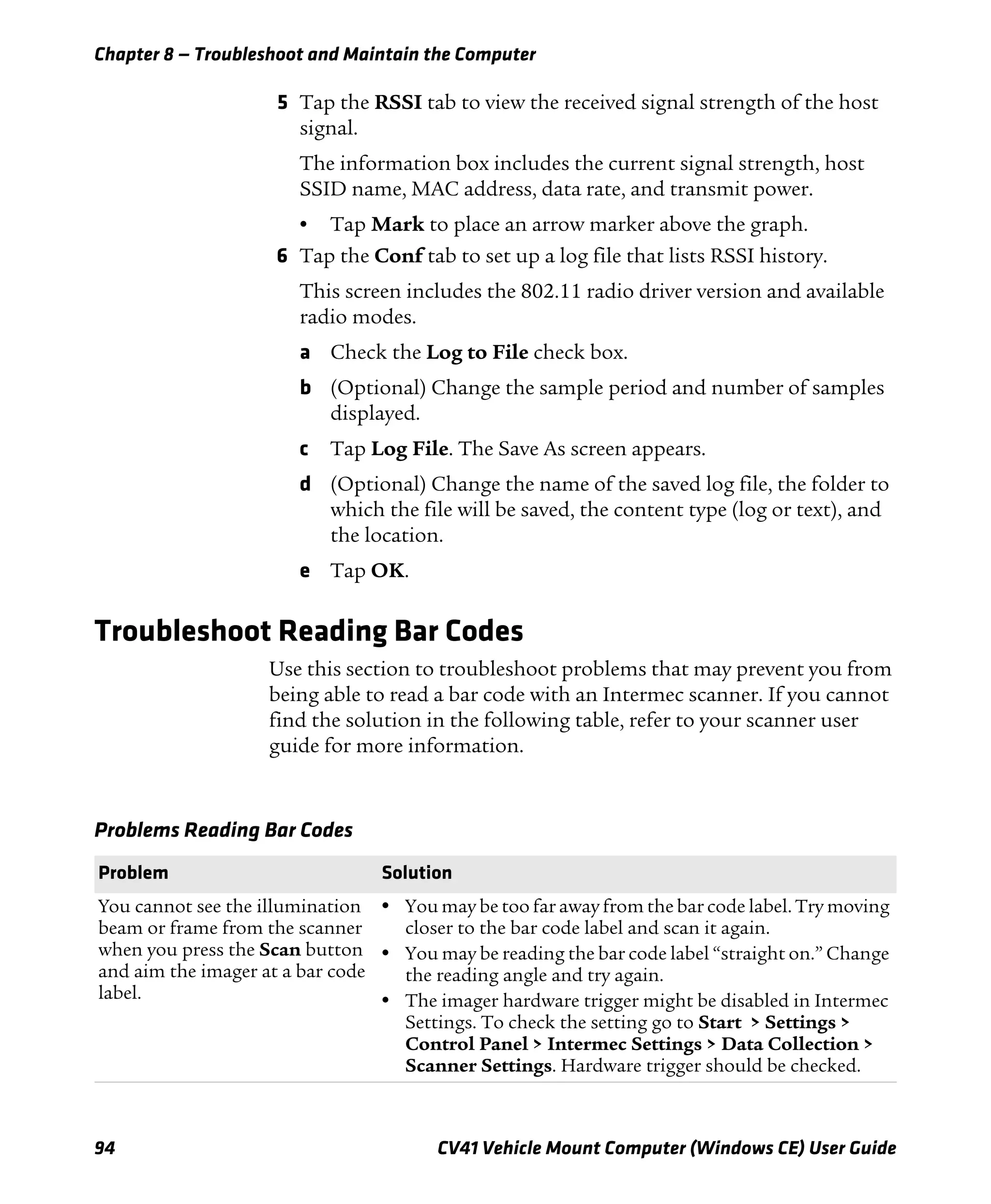


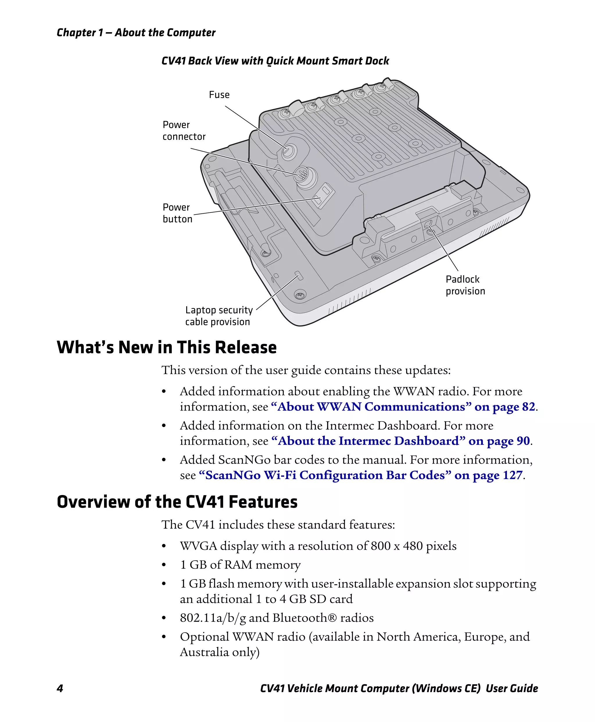
![Appendix B — Keypads and Keystrokes
CV41 Vehicle Mount Computer (Windows CE) User Guide 123
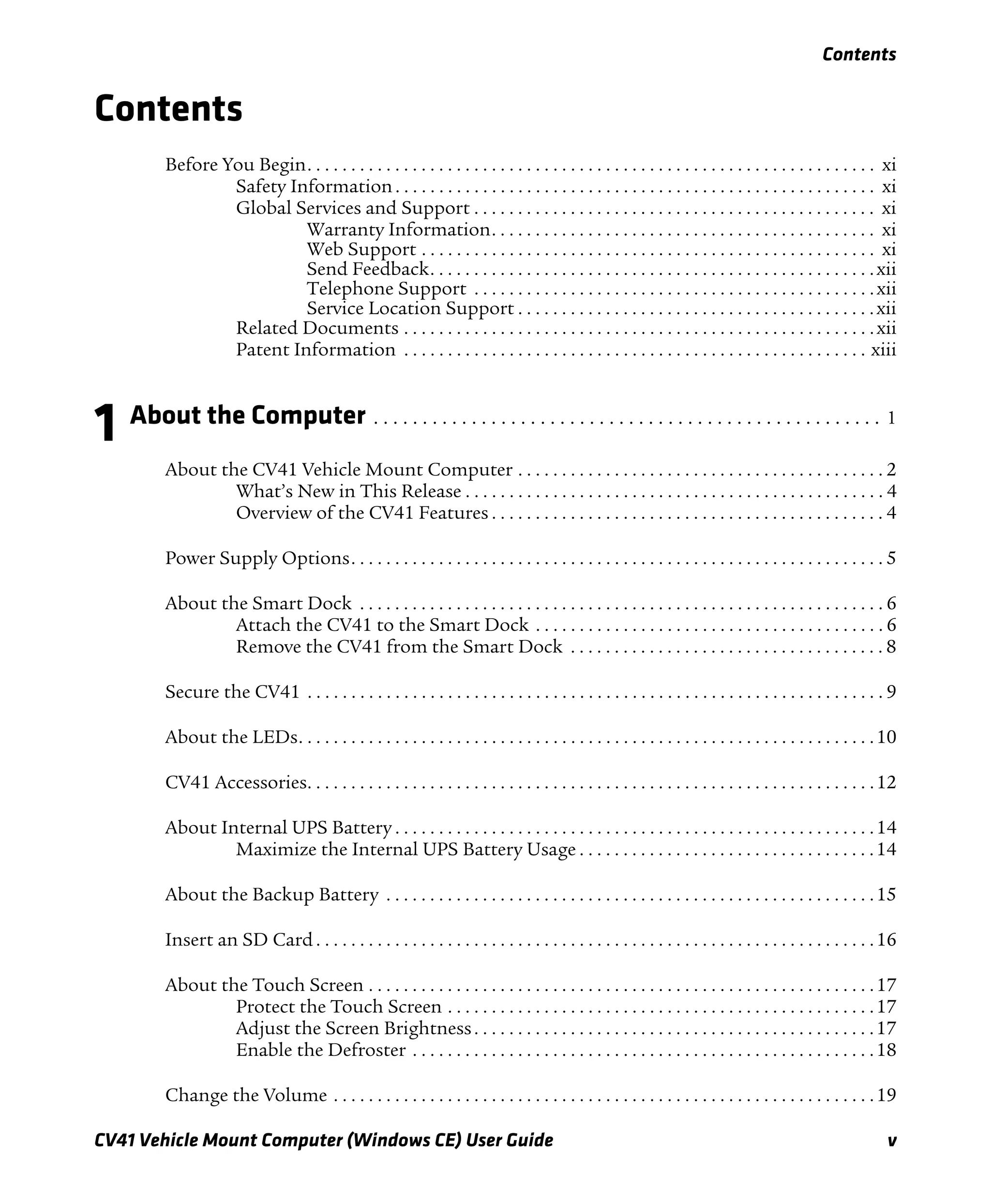
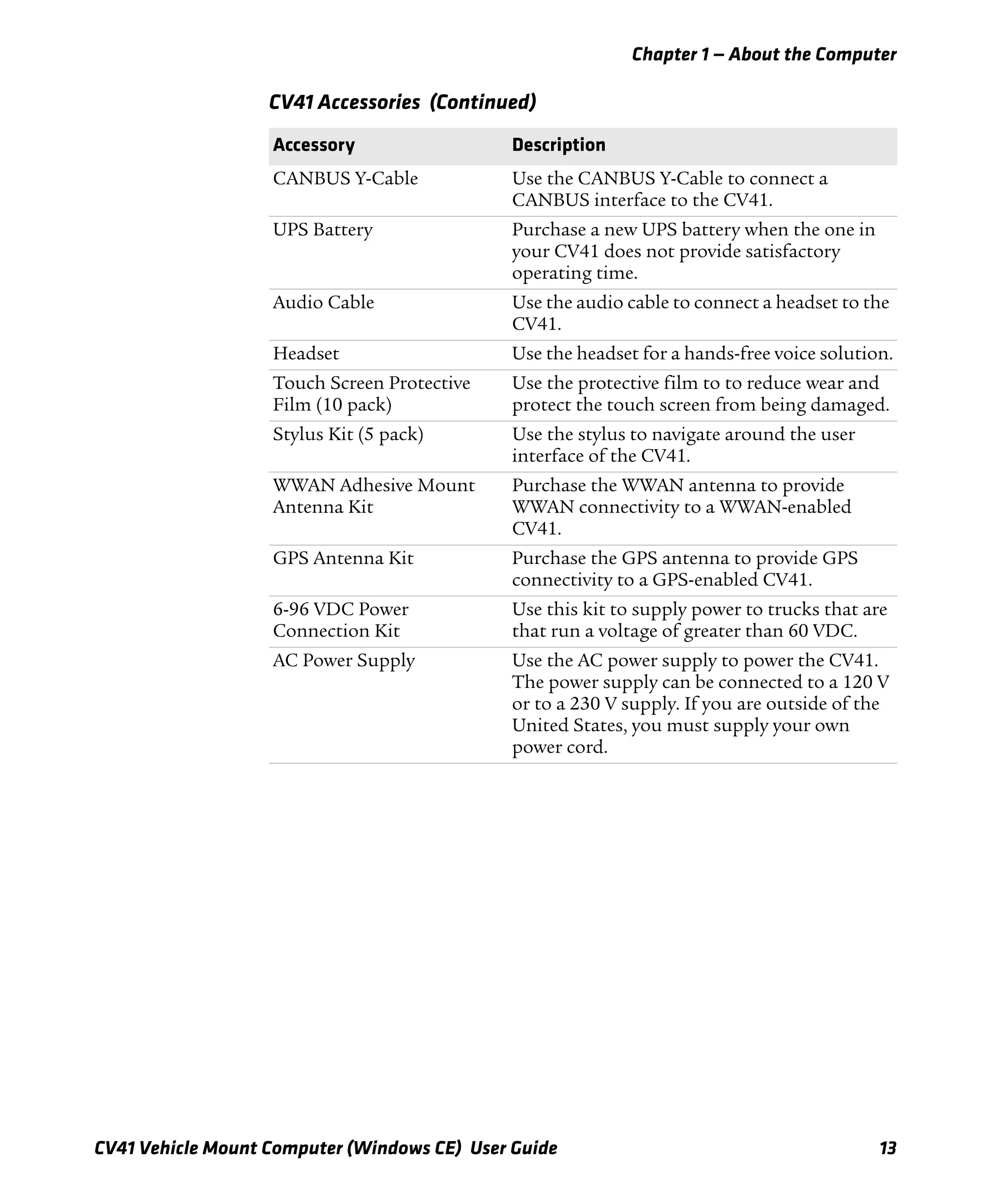
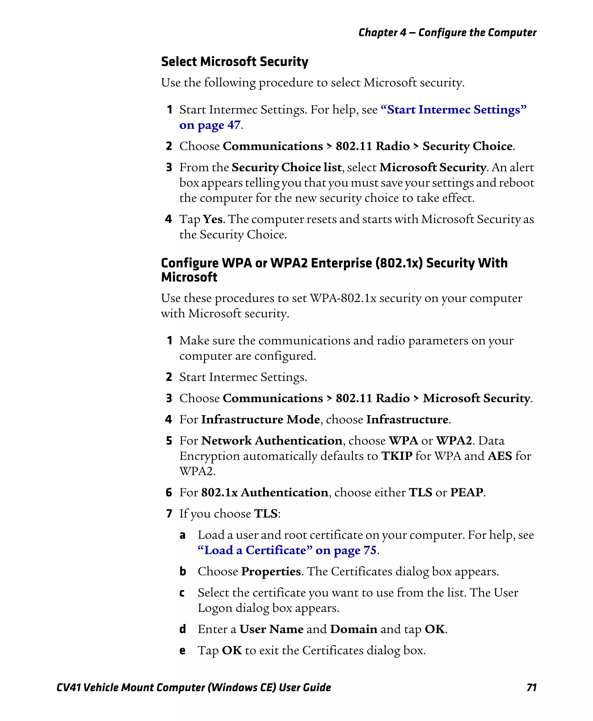
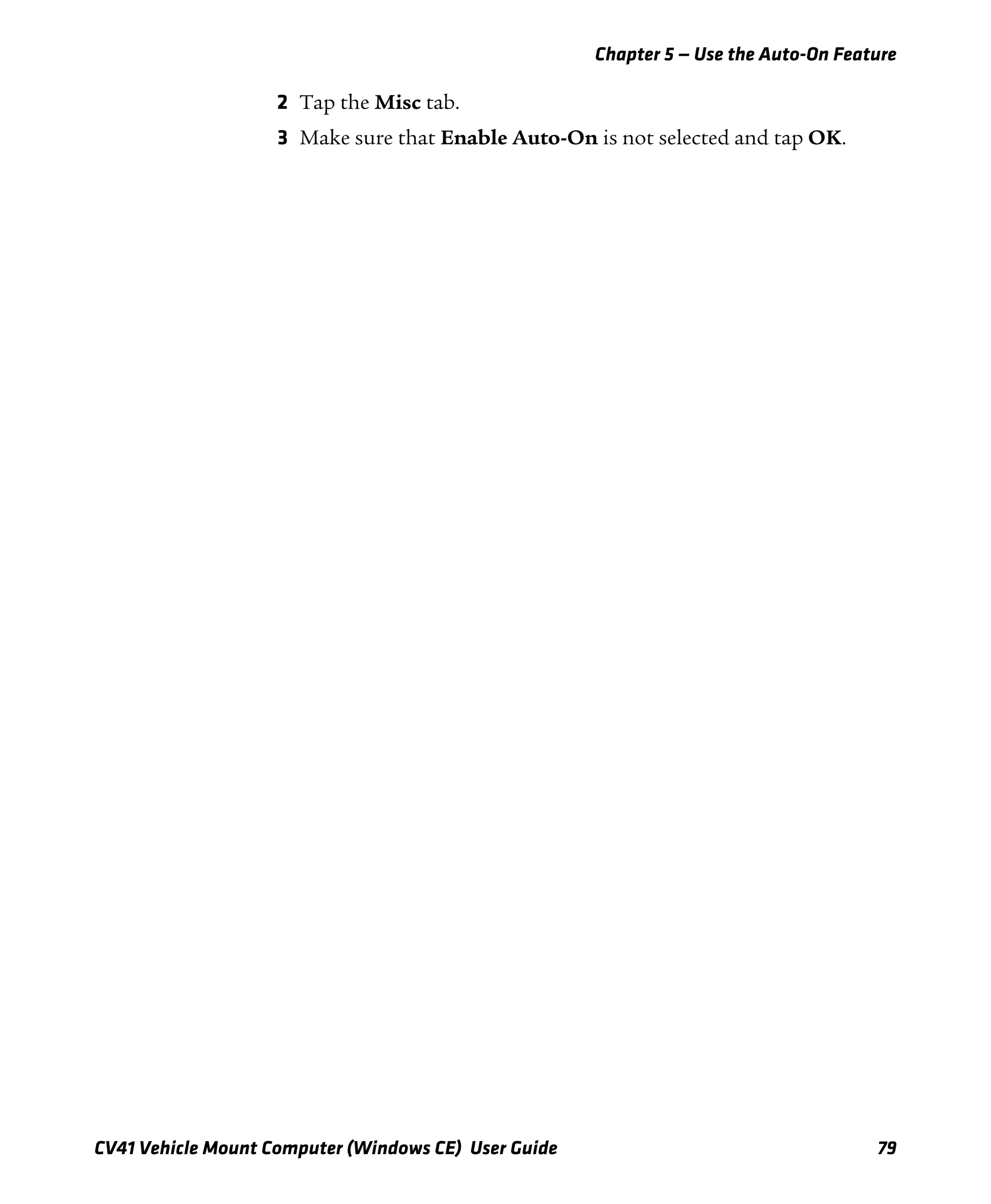
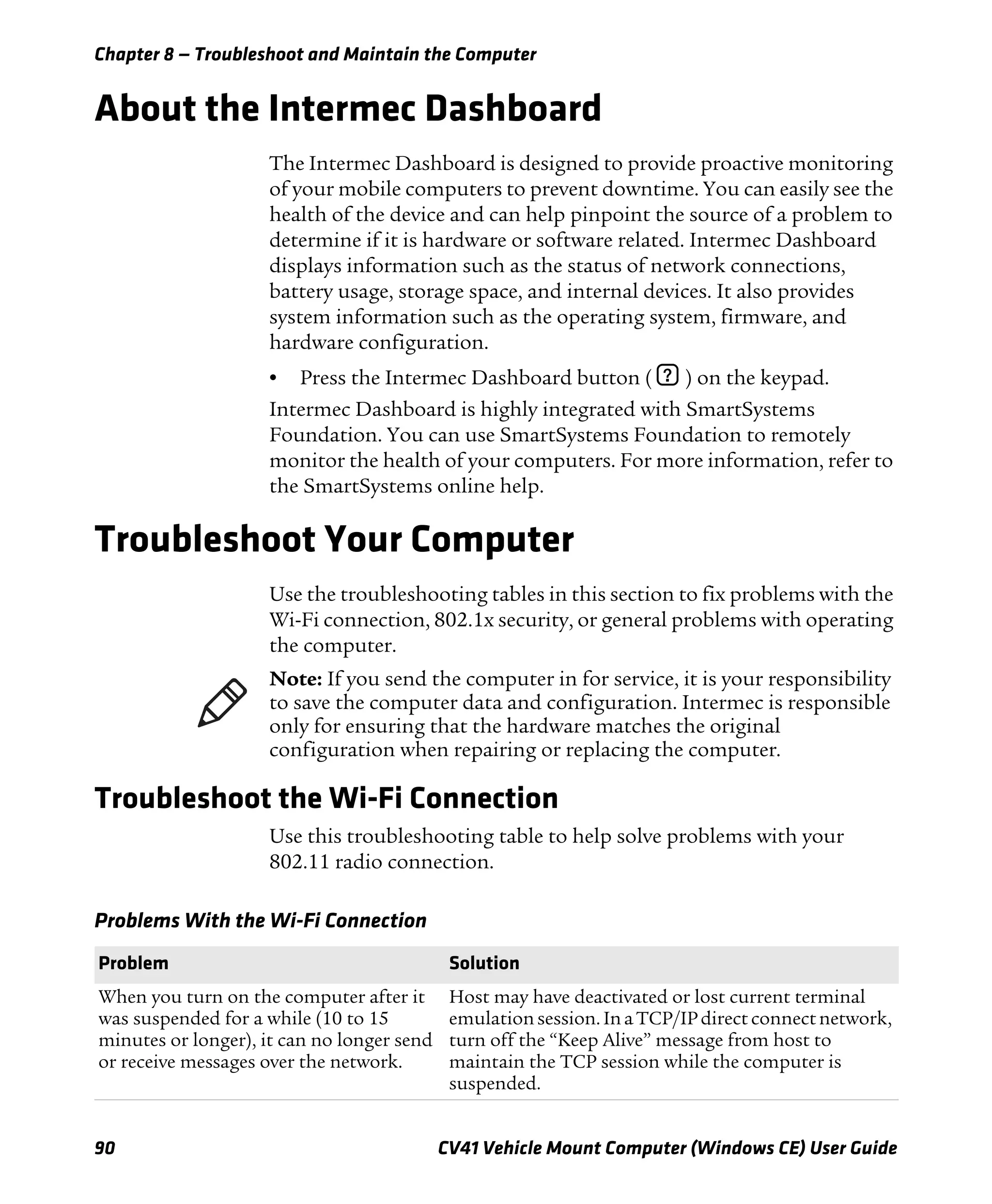
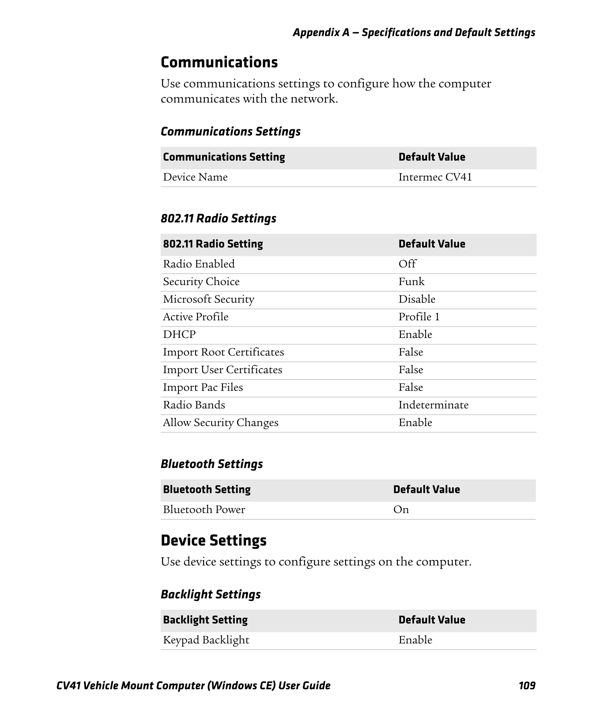
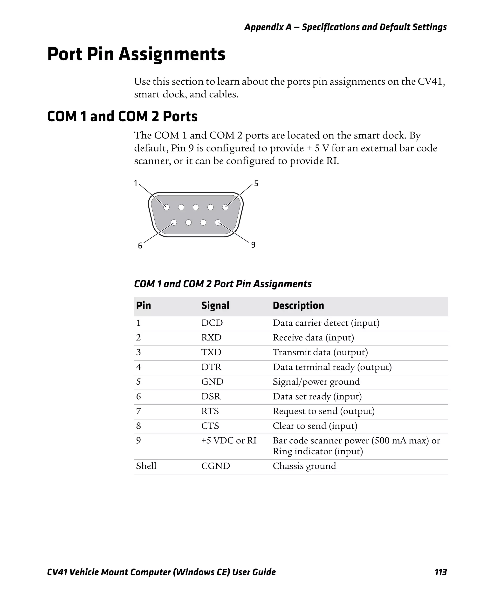
+ (plus) b 8
‘ (apostrophe) b H
= (equals) b 2
_ (underscore) b M
^ (caret) b u
> (greater than) b V
< (less than) b C
( (left parenthesis) b O
) (right parenthesis) b P
[ (left square bracket) b B
] (right square bracket) b N
{ (left curly brace) b Z
} (right curly brace) b X
~ (tilde) b s
(backslash) b S
/ (forward slash) b A
“ (quotes) b G
Insert b 4
Delete b 6
¦ (broken vertical bar) b {
̀ (grave) b |
Forward Tab j
Backspace {
Up Arrow u
Down Arrow d
CV41 Special Keys (Continued)
To Enter Keypad](https://image.slidesharecdn.com/manualdousuariowindowsce-160429180048/75/Manual-CV41-137-2048.jpg)
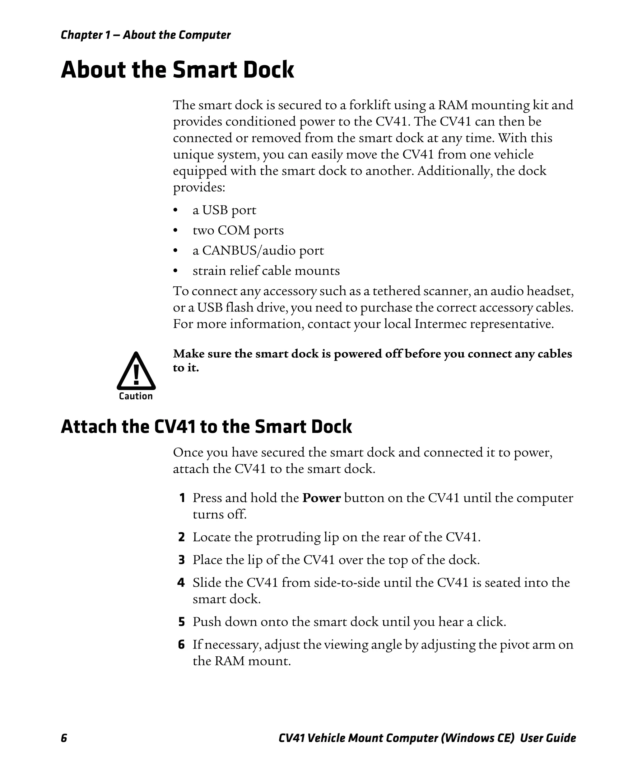
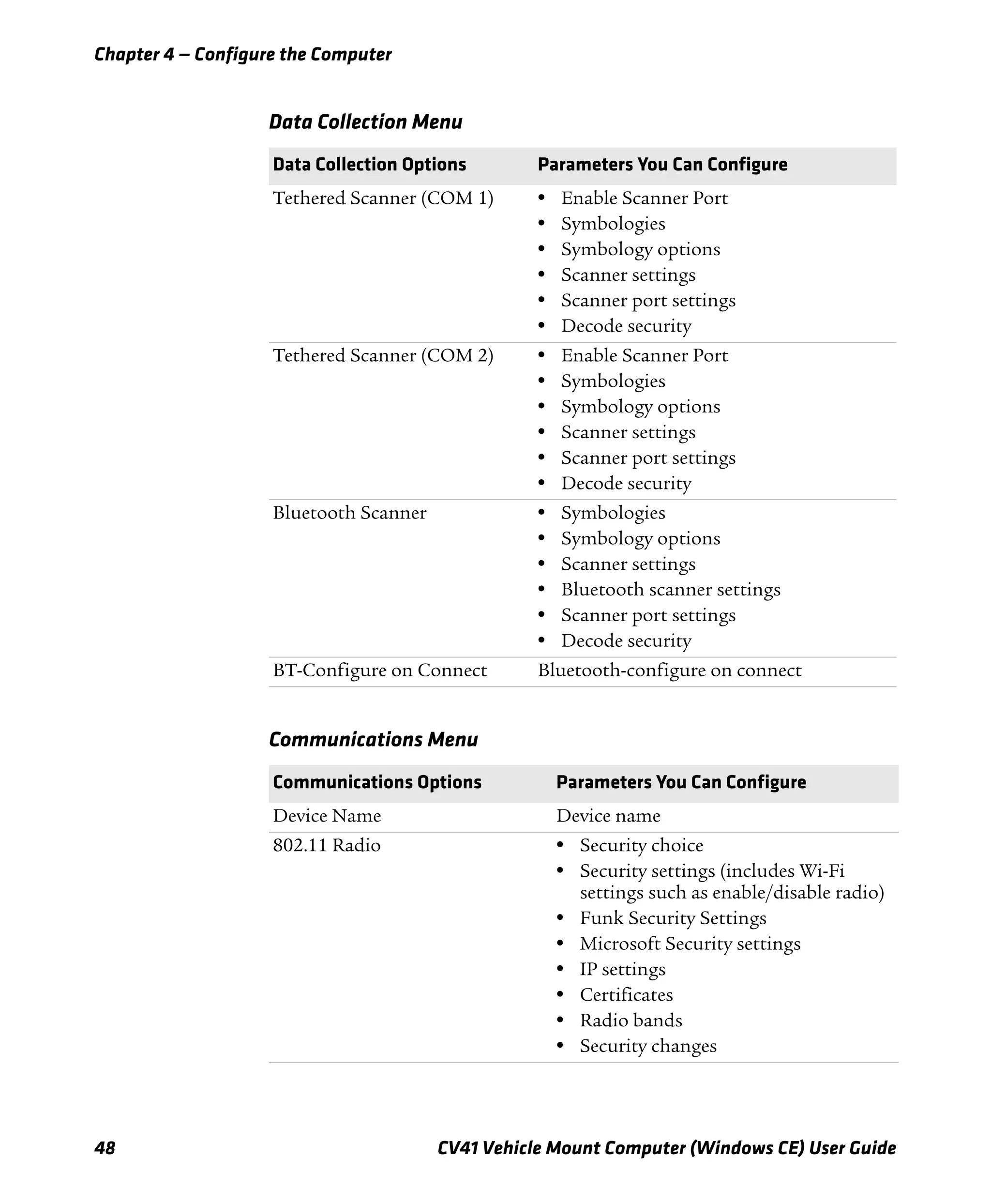
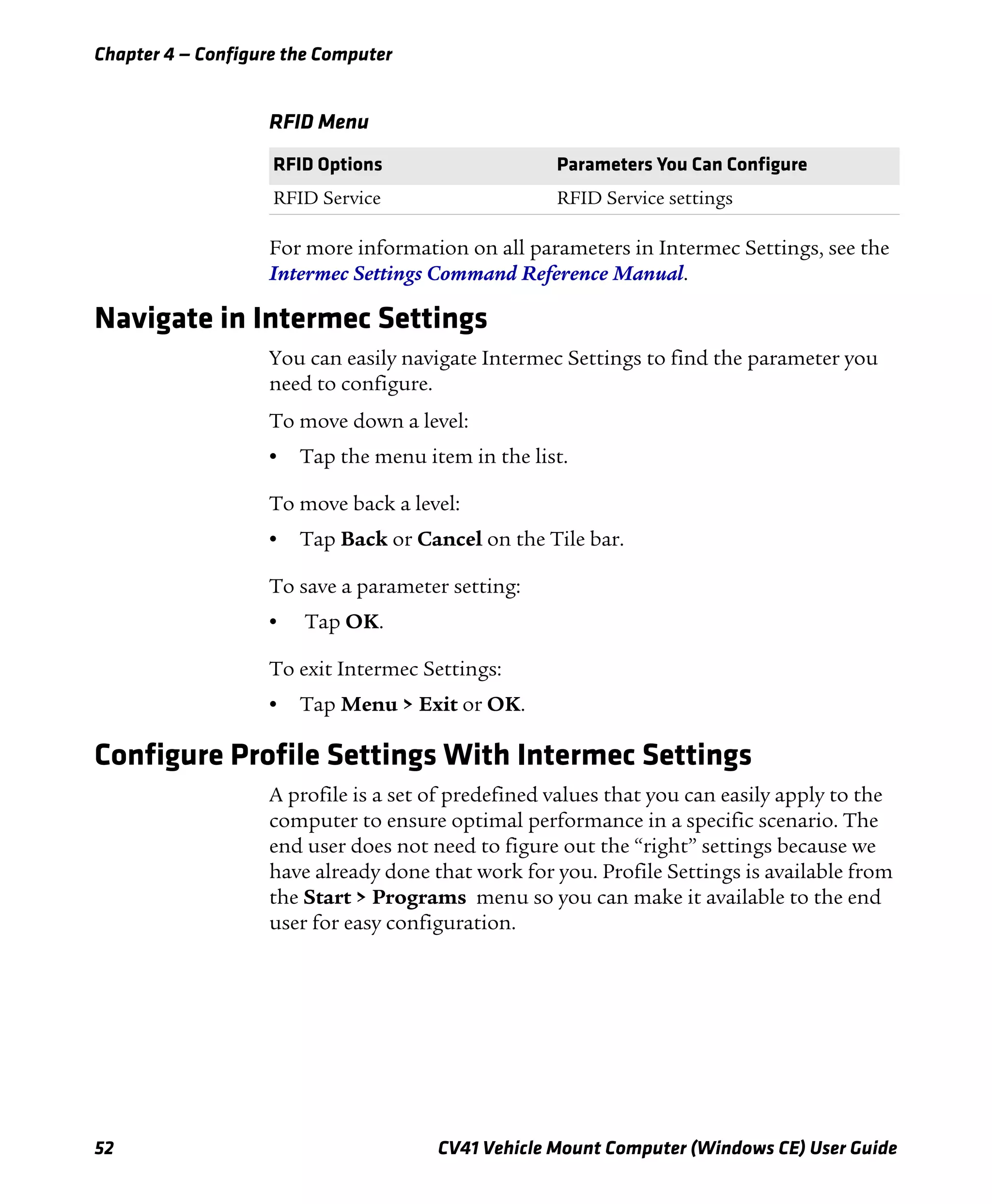
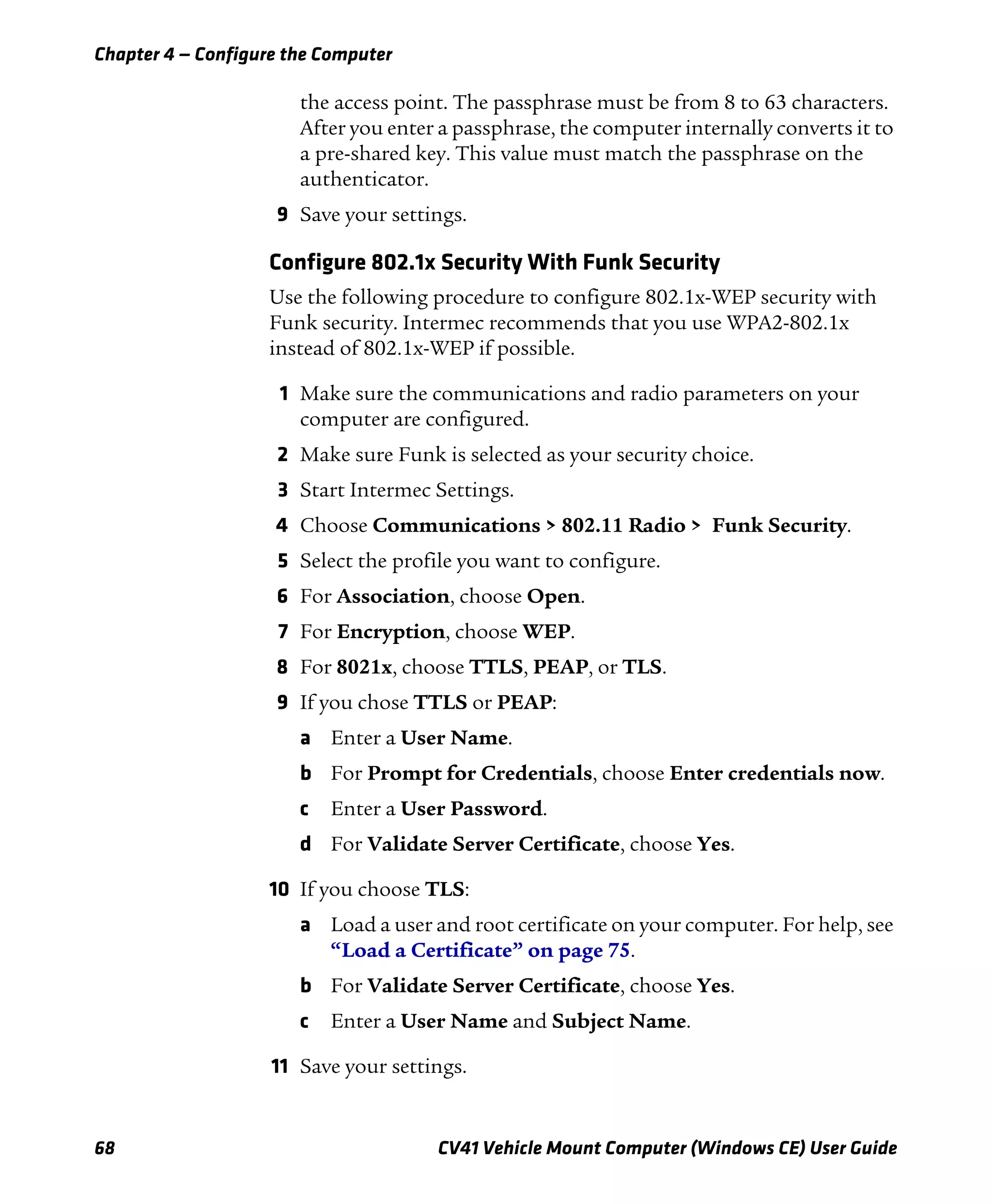
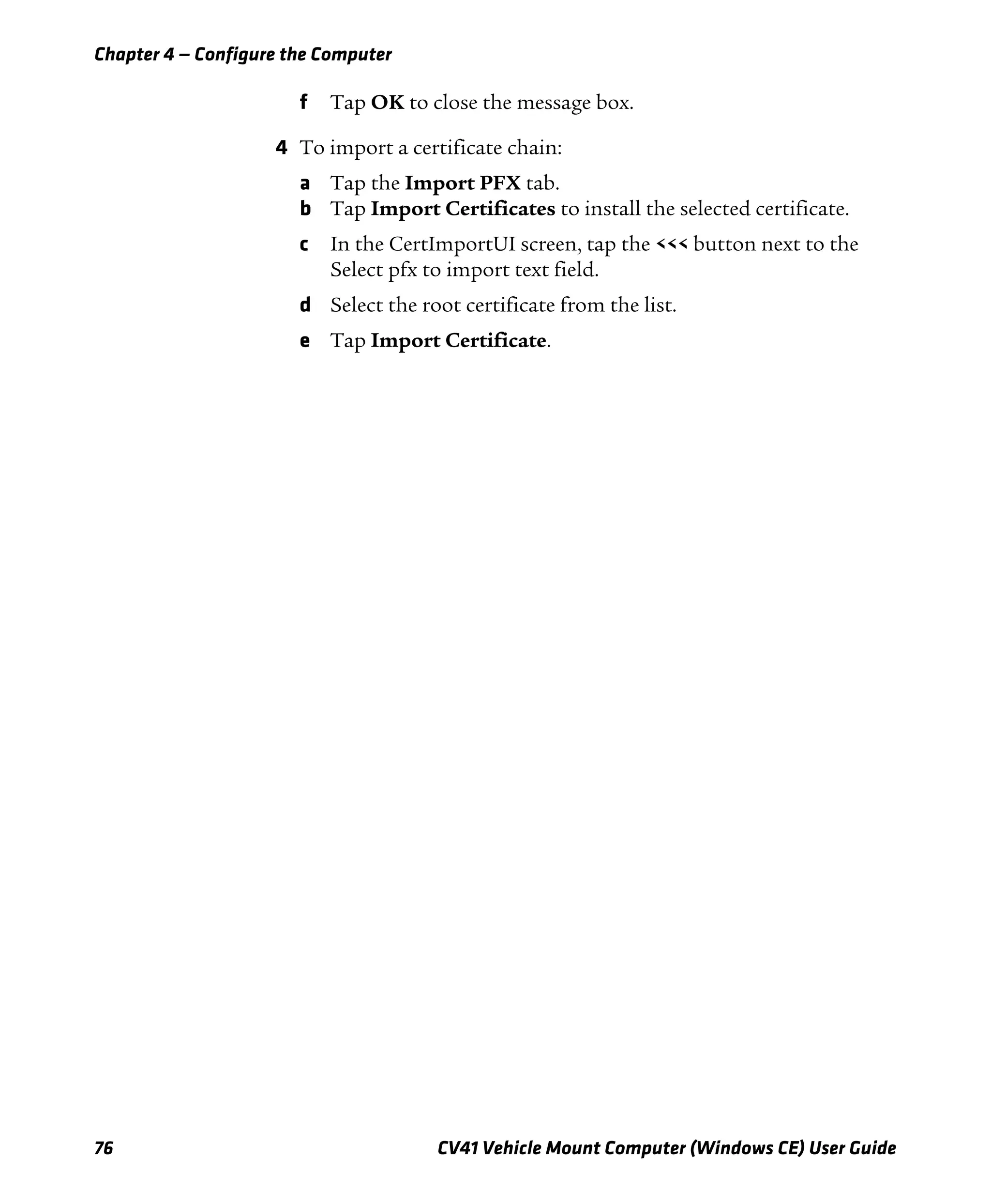
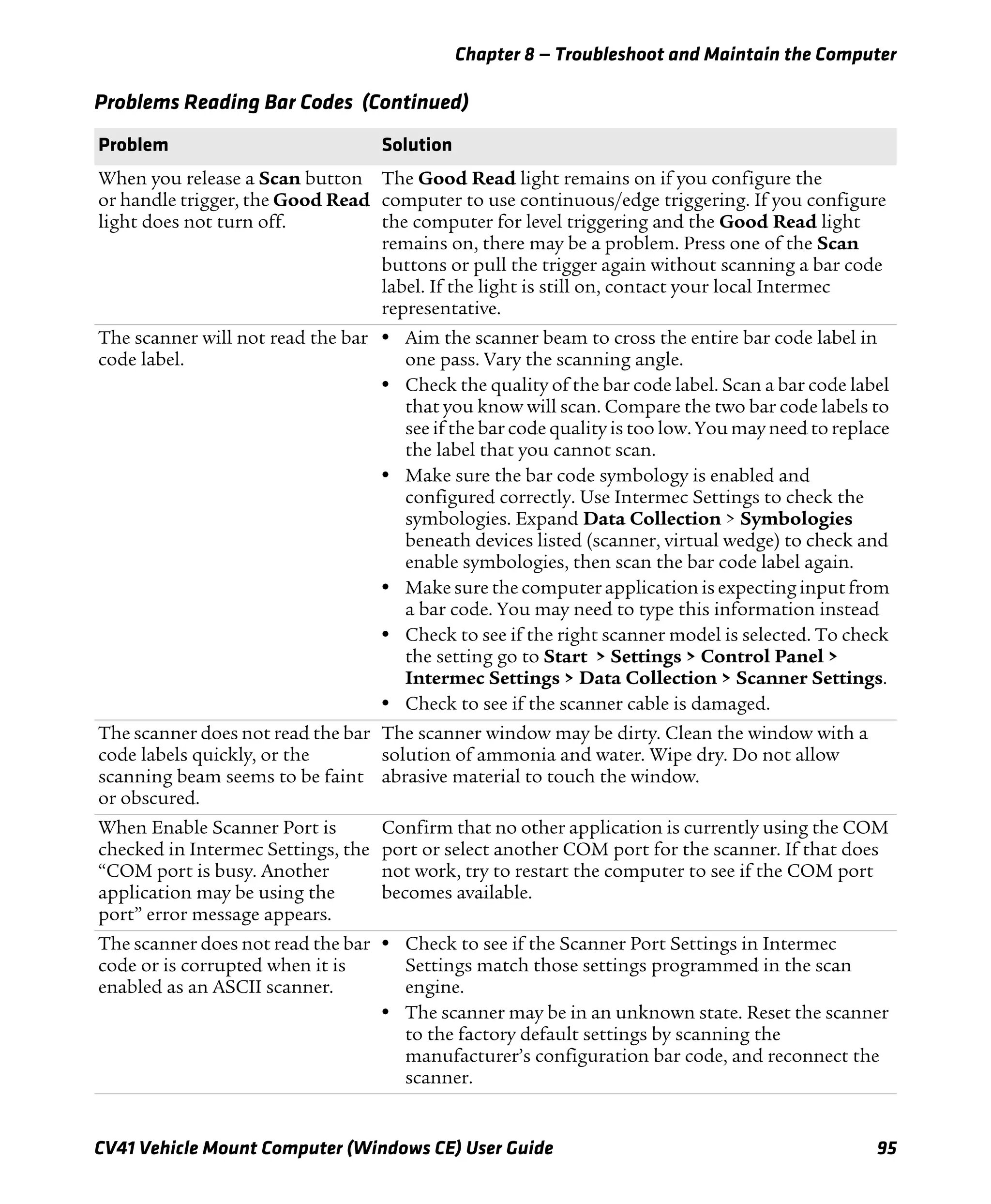
![Appendix B — Keypads and Keystrokes
124 CV41 Vehicle Mount Computer (Windows CE) User Guide
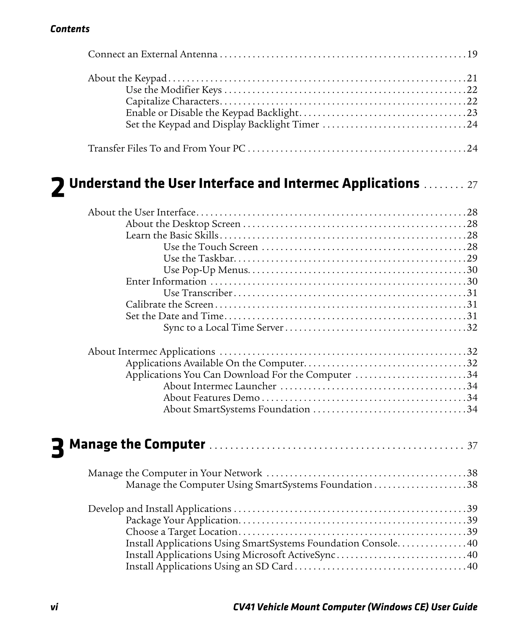
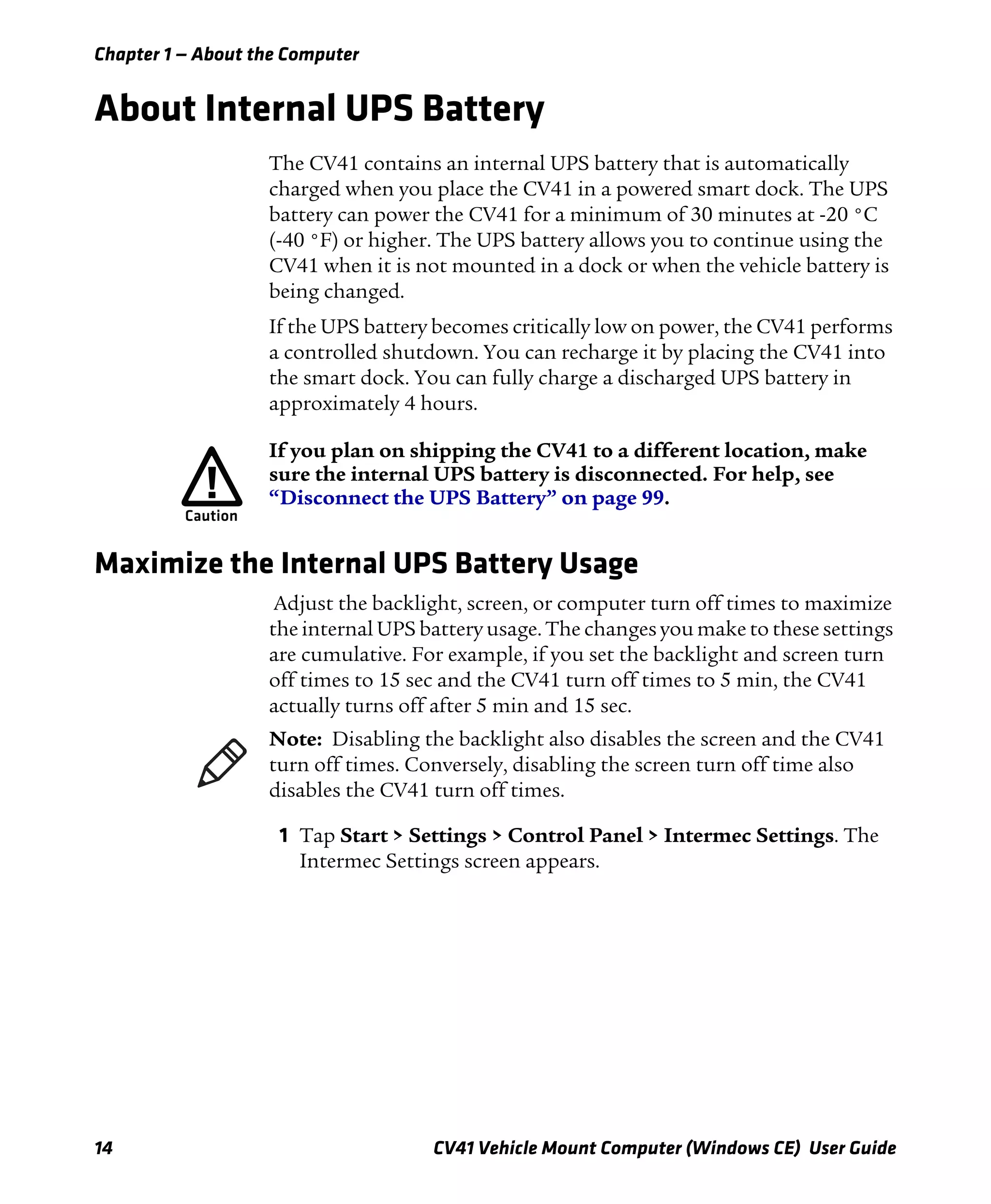
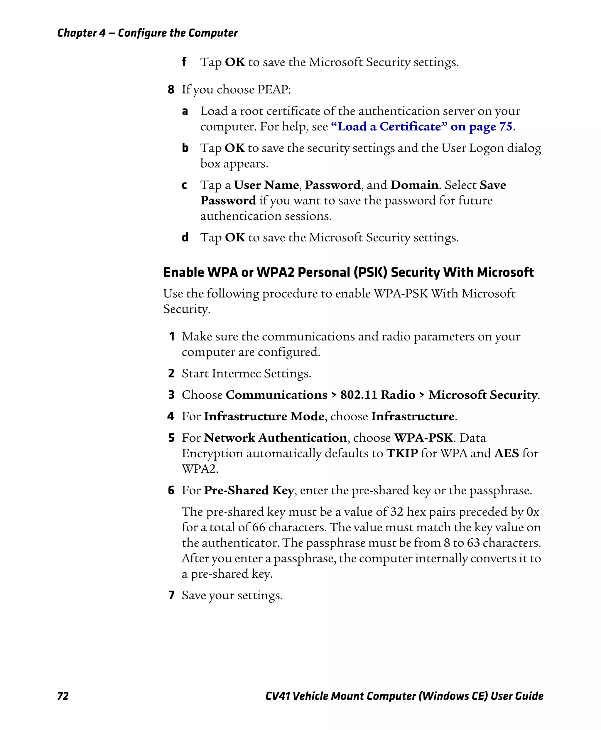
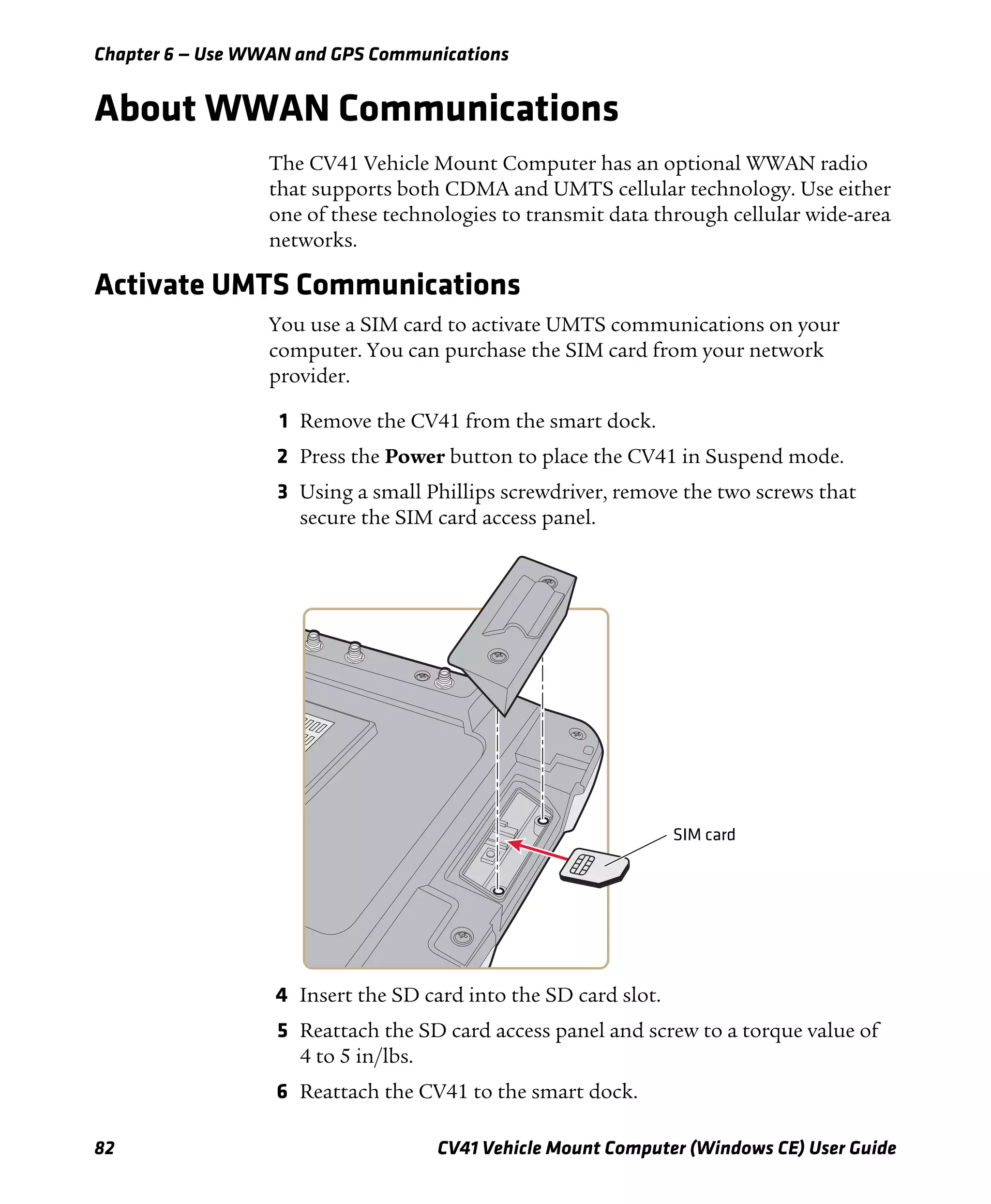
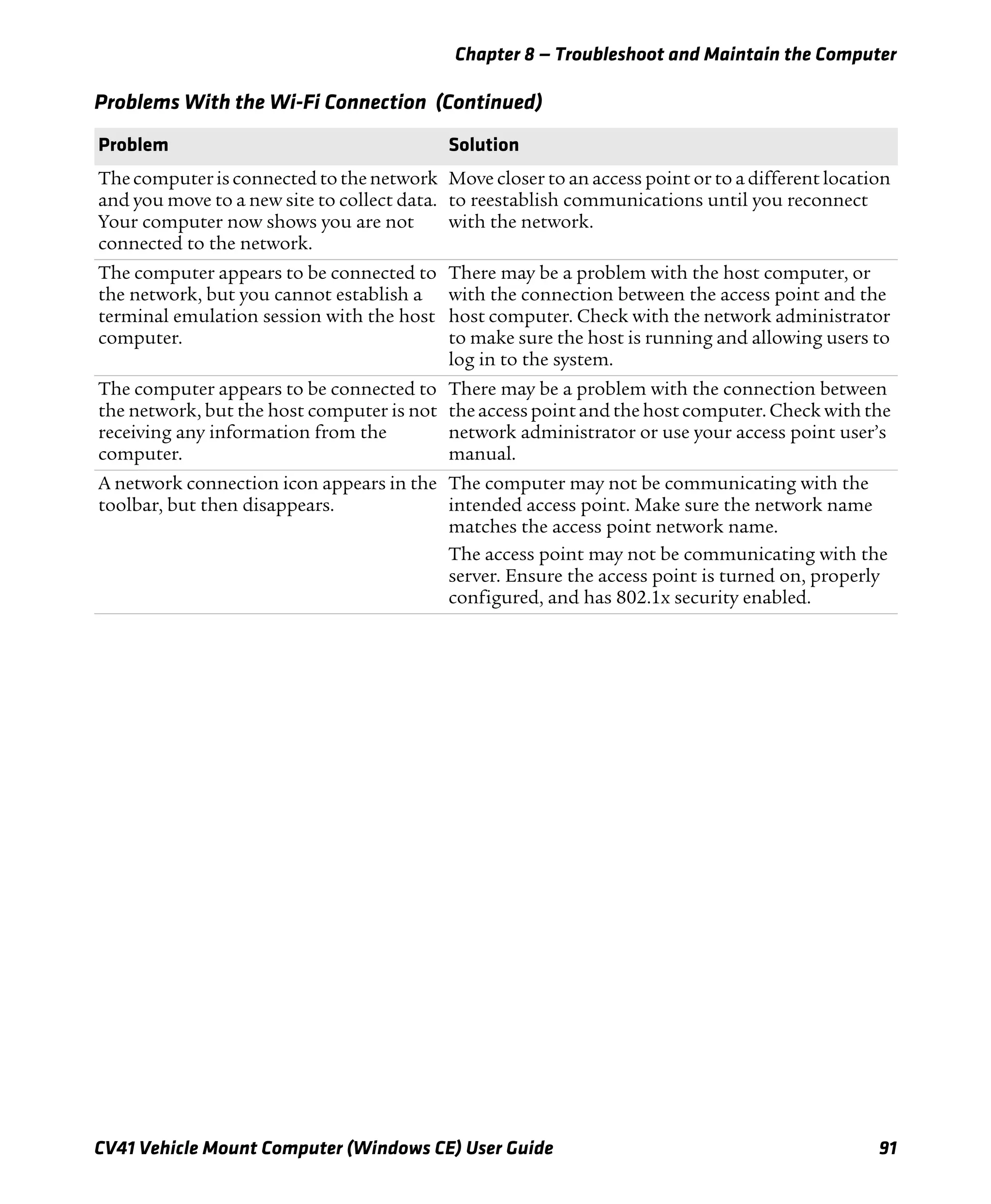
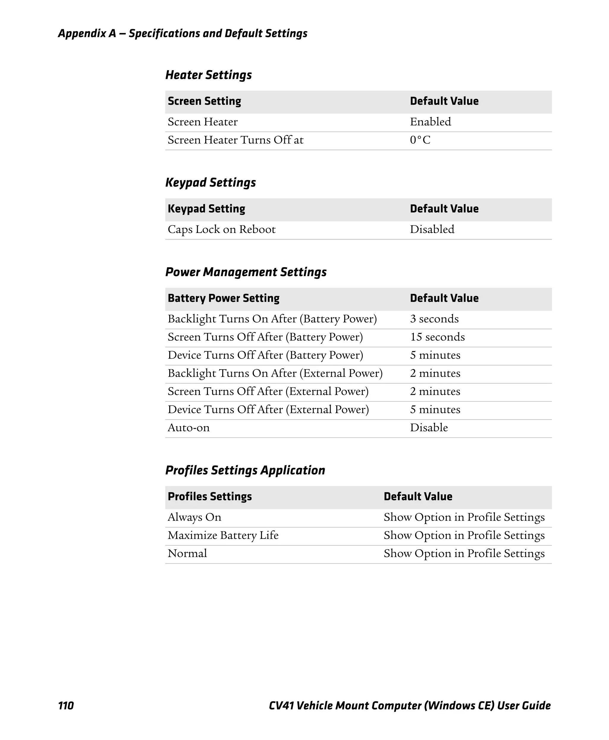
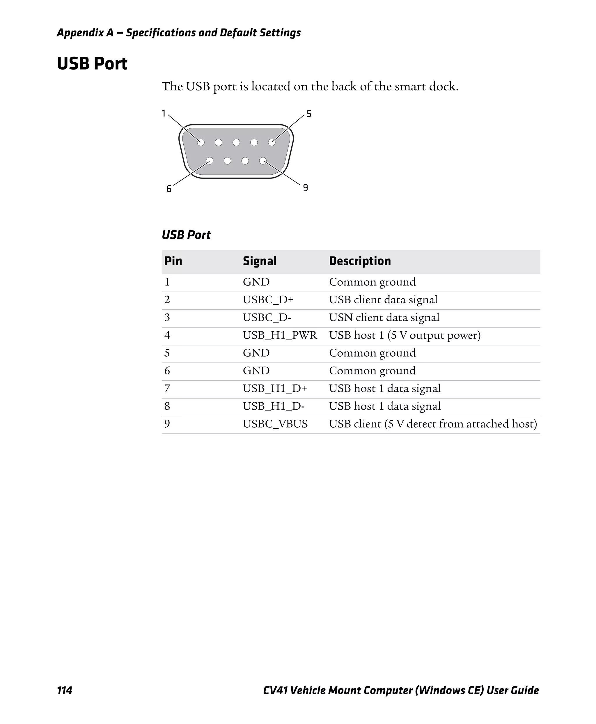
Left Arrow l
Right Arrow r
CapsLock b ]
Enter e
ok Alt o
Shift ]
Space s
Start (Windows) ? or b ?
Esc |
Alt Alt
Ctrl Ctrl
Intermec Dashboard ?
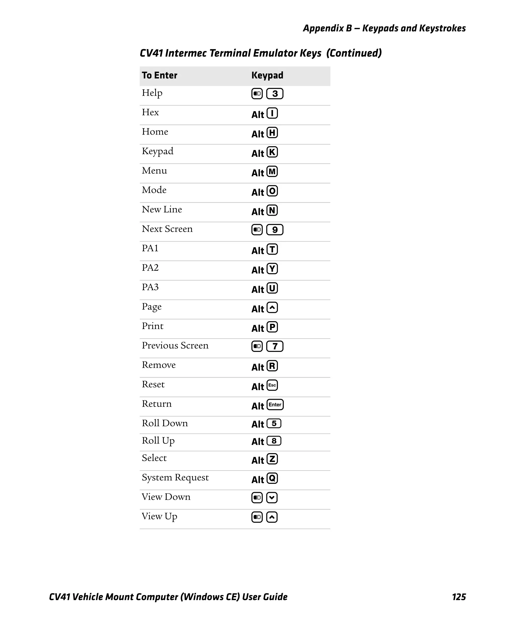
CV41 Intermec Terminal Emulator Keys
To Enter Keypad
Attention Alt A
Autolog Alt S
Clear Alt 6
Duplicate Alt D
EEOF Alt W
Erase Alt E
Find Alt F
Field + b 1
Field - Alt 2
Fieldmark Alt G
CV41 Special Keys (Continued)
To Enter Keypad](https://image.slidesharecdn.com/manualdousuariowindowsce-160429180048/75/Manual-CV41-138-2048.jpg)


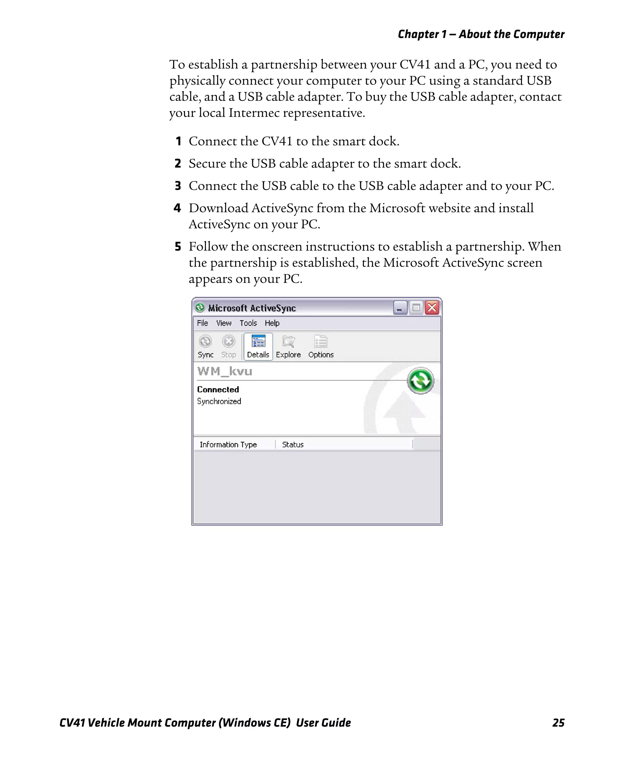
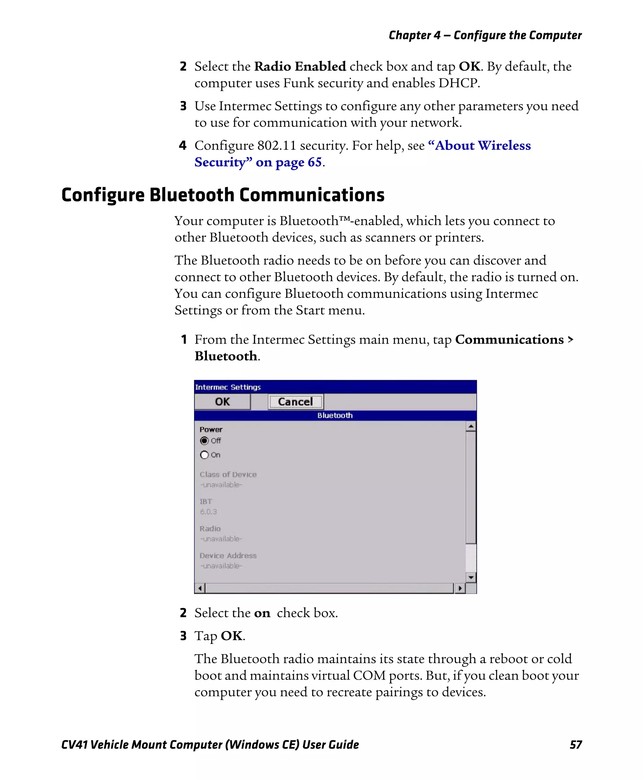
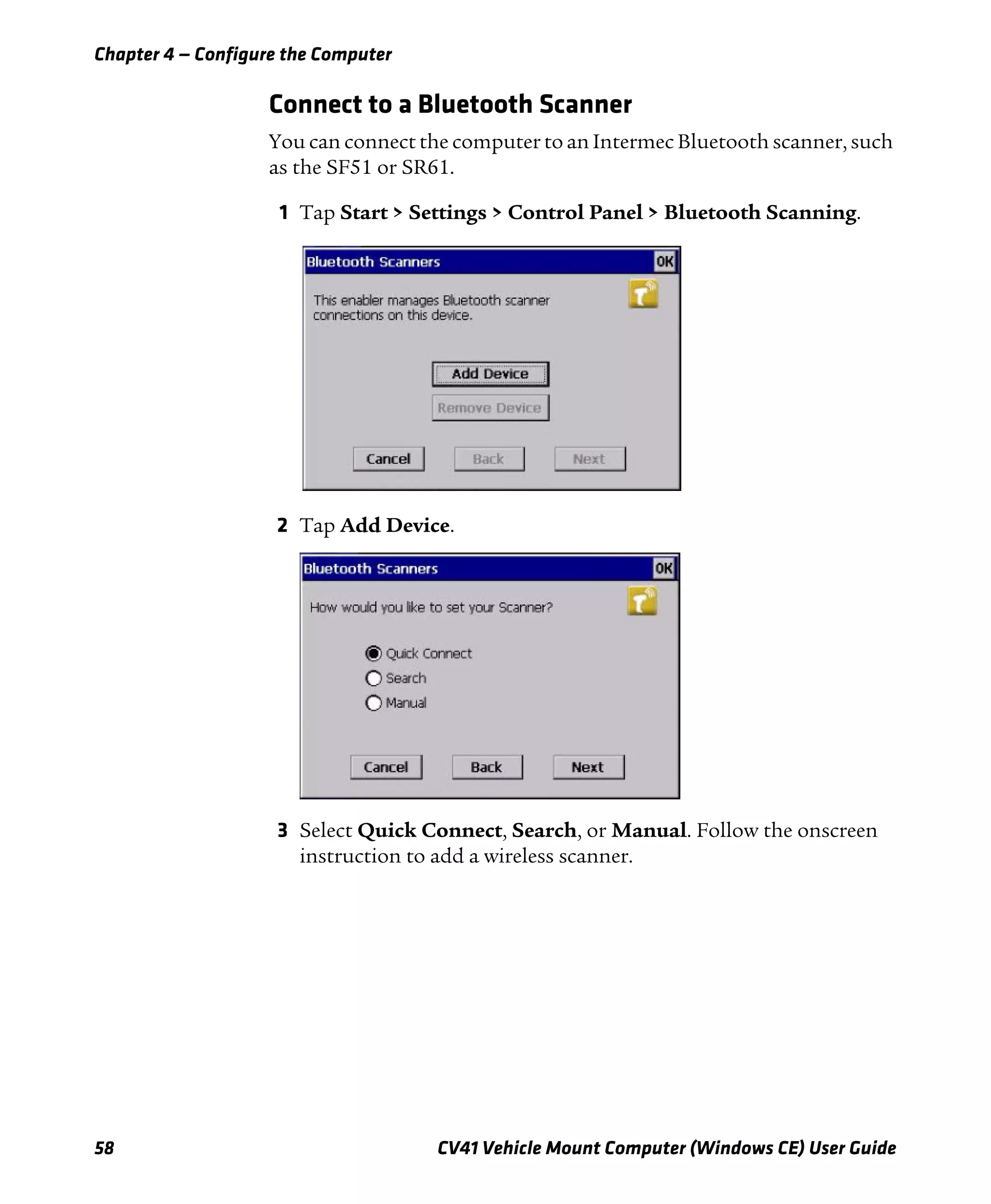
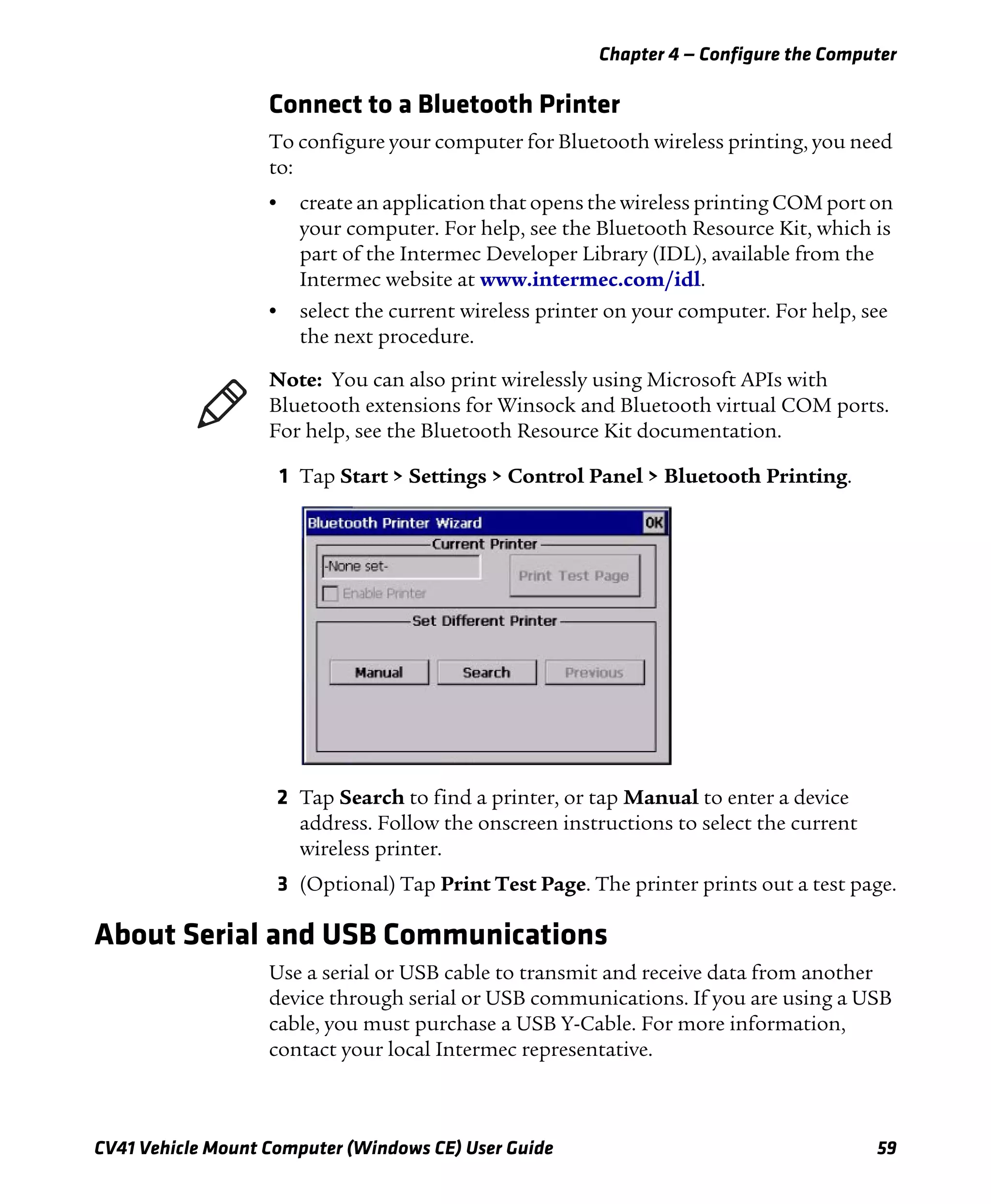
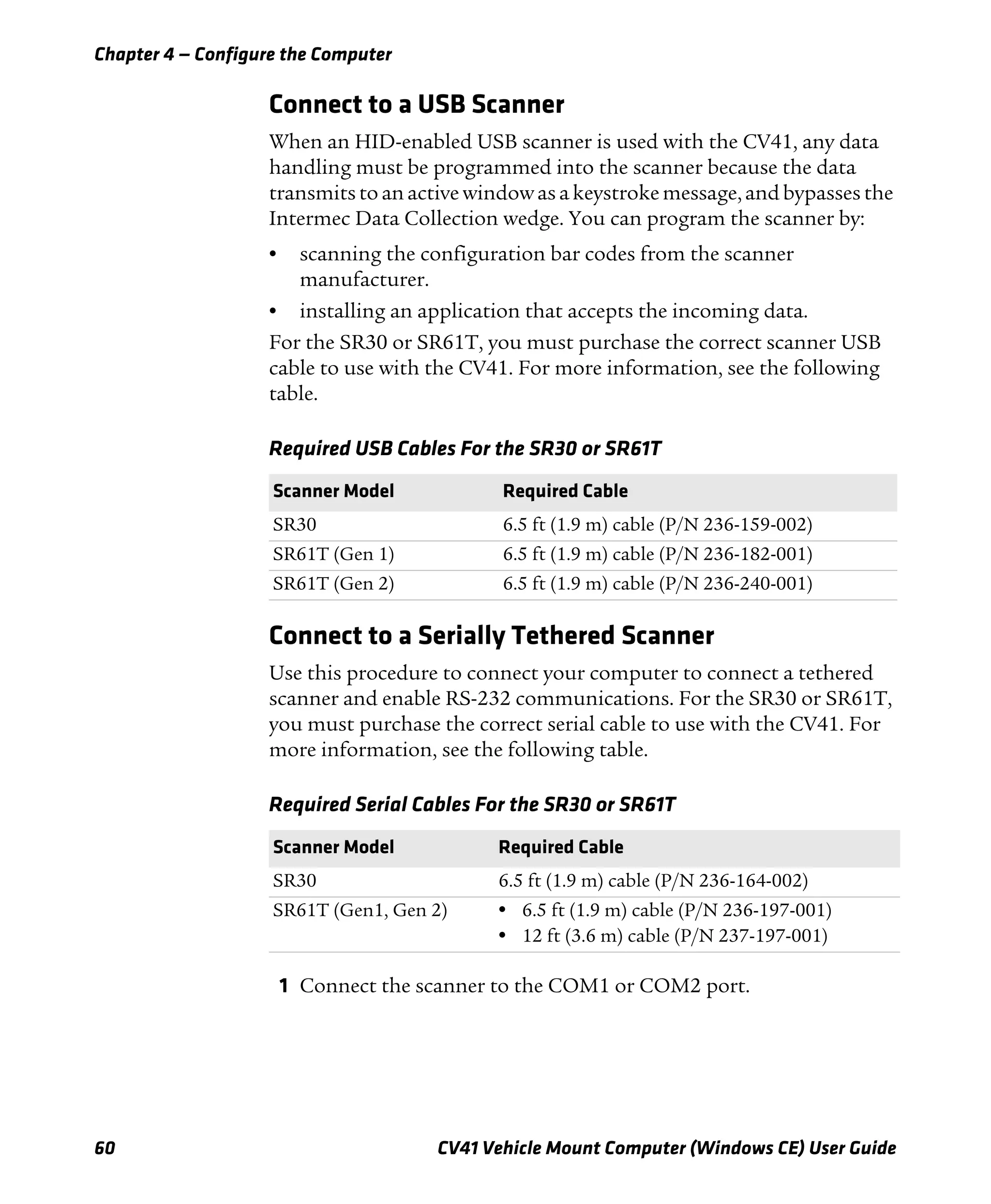
This document is a user guide for the CV41 vehicle mount computer running Windows CE. It provides information about operating and maintaining the computer such as attaching and removing it from the mounting dock, using accessories like the touchscreen and keypad, connecting power and antennas, transferring files, and understanding the user interface and included applications. The guide also describes how to manage the computer within a network using Intermec's SmartSystems Foundation software and how to develop and install custom applications.


