Downloaded 57 times


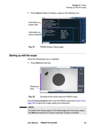
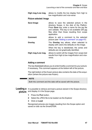
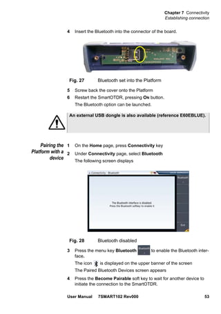
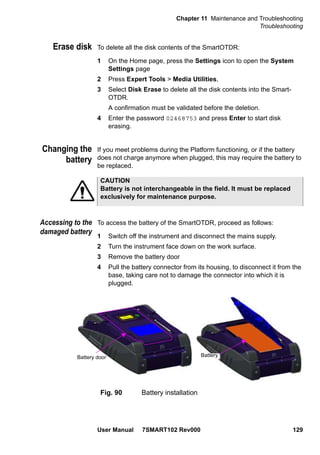
![About This Guide
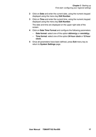
Conventions
User Manual 7SMART102 Rev000 xvii
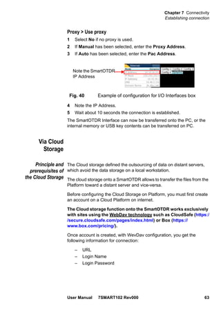
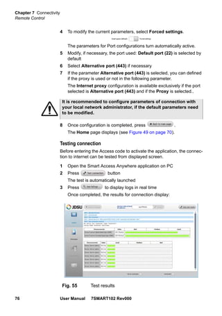
During off-hours, you can request assistance by doing one of the
following:
– leave a voice mail message at the Technical Assistance number in
your region
– e-mail North American Technical Assistance Center, tac@jdsu.com,
or European Technical Assistance Center, support.uk@jdsu.com
– submit your question using our online Technical Assistance Request
form at www.jdsu.com.
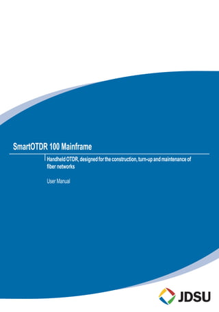
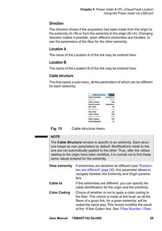
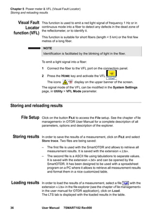
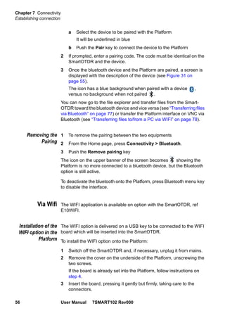
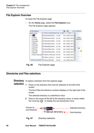
Conventions
This guide uses naming conventions and symbols, as described in the
following tables.
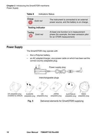
Table 2 Typographical conventions
Description Example
User interface actions appear in
this typeface.
On the Status bar, click Start.
Buttons or switches that you
press on a unit appear in this
TYPEFACE.
Press the ON switch.
Code and output messages
appear in this typeface.
All results okay
Text you must type exactly as
shown appears in this type-
face.
Type: a:set.exe in the dia-
log box
Variables appear in this type-
face.
Type the new hostname
Book references appear in this
typeface.
Refer to Newton’s Telecom
Dictionary
A vertical bar | means “or”: only
one option can appear in a sin-
gle command.
platform [a|b|e]
Square brackets [ ] indicate an
optional argument.
login [platform name]
Slanted brackets < > group
required arguments.
<password>](https://image.slidesharecdn.com/smartotdrusermanualen-160902210100/85/Smart-otdr-JDSU-17-320.jpg)


![Chapter 5 Power meter & VFL (Visual Fault Locator)
Using the Power meter via USB port
32 User Manual 7SMART102 Rev000
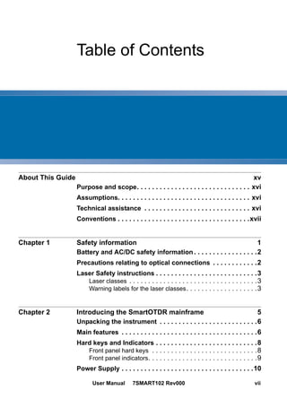
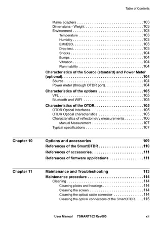
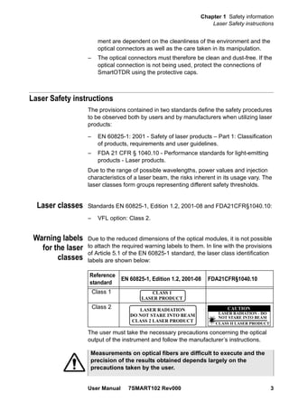
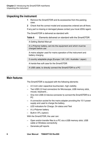
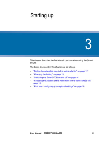
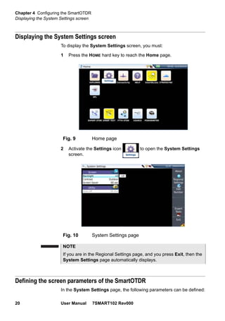
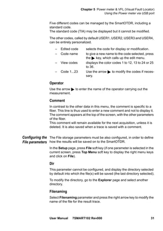
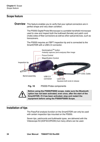
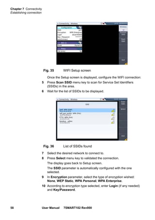
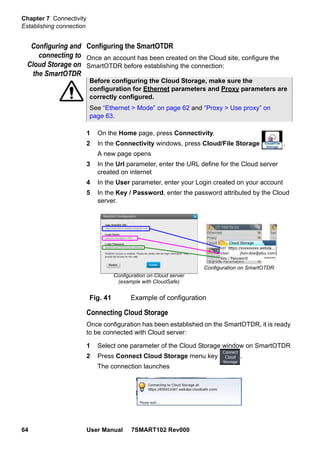
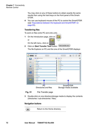
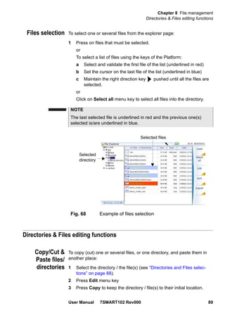
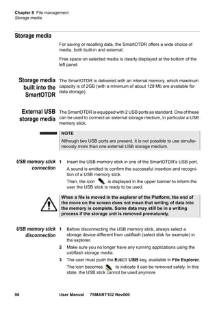
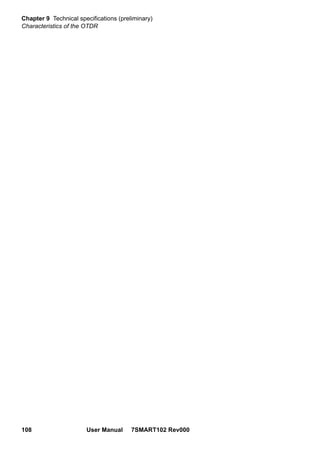
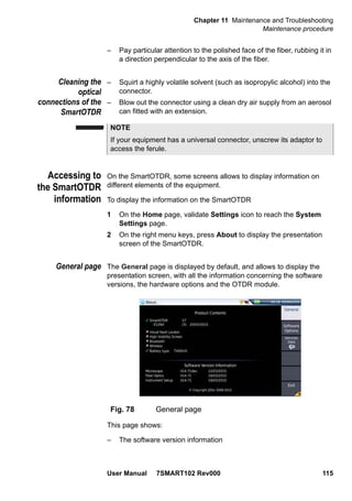
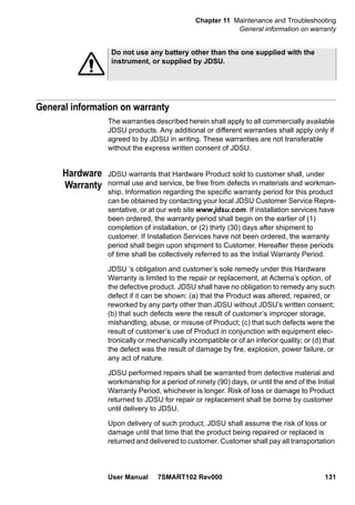
In the edition keypad, enter a name manually for the file and/or use
the predefined parameters available (Cable_Id, Fiber_Num...).
Then, press Enter to validate.
or
Press Default Filename to apply the name by default to the file:
Fiber[Cable_Id][Fiber_Num]_[Lambda]_[Direction]
The name of the file is displayed in grey under Filenaming parameter
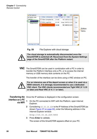
Save Mode
When a trace or more is displayed, in the parameter Save Mode, you can
select three types of methods for storing traces:
File Only only the trace(s) is/are stored in one/several file(s),
with its extension (.sor, .msor)
File + txt the trace(s) is/are stored in one/several file(s), with its
extension and one txt file is also generated.
Display of
results and
commands
The results page called up by the RESULTS button, gives the information
relating to the measurement in progress, results previously saved and
the commands available for measurement and saving.
Result of the
measurement in
progress
The power measured by the power meter is displayed in large charac-
ters, in the units selected in the SETUP menu, together with:
– the mode of transmission of the signal measured: continuous (CW)
or modulated to a frequency of 270Hz, 330Hz, 1KHz, or 2KHz.
– the wavelength of the signal measured.
– the reference level expressed in dB.
– the level of Attenuation Compensation.
Fig. 16 Filenaming - Edition keypad
Predefined
parametersfor
naming files](https://image.slidesharecdn.com/smartotdrusermanualen-160902210100/85/Smart-otdr-JDSU-50-320.jpg)


The document is a user manual for the SmartOTDR 100 Mainframe handheld OTDR. It provides instructions on safety, starting up the device, configuring settings, using the integrated power meter and visual fault locator, scope feature, connectivity options, and remote control capabilities. The manual guides the user on unpacking, charging batteries, making measurements, storing results, and connecting to other devices via Bluetooth, WiFi, Ethernet, or cloud storage for remote operation and file sharing.


