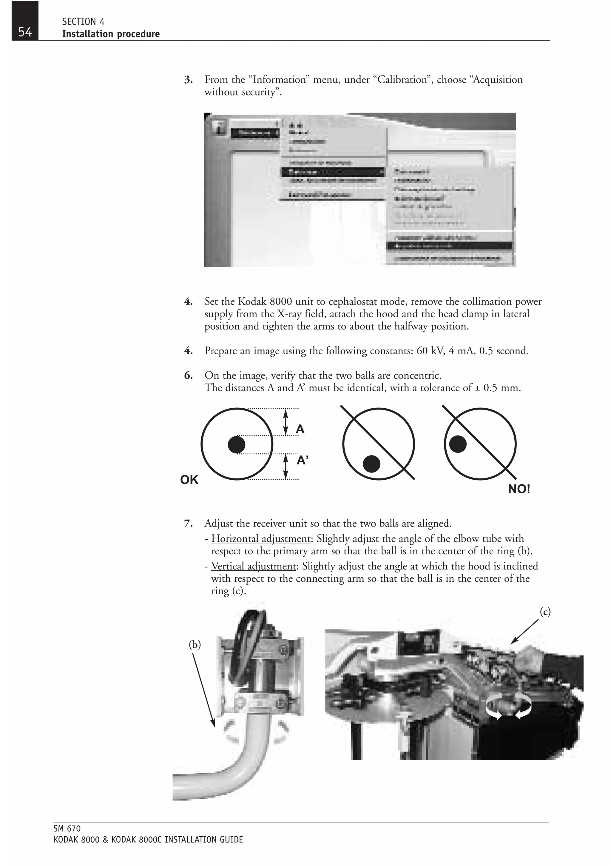
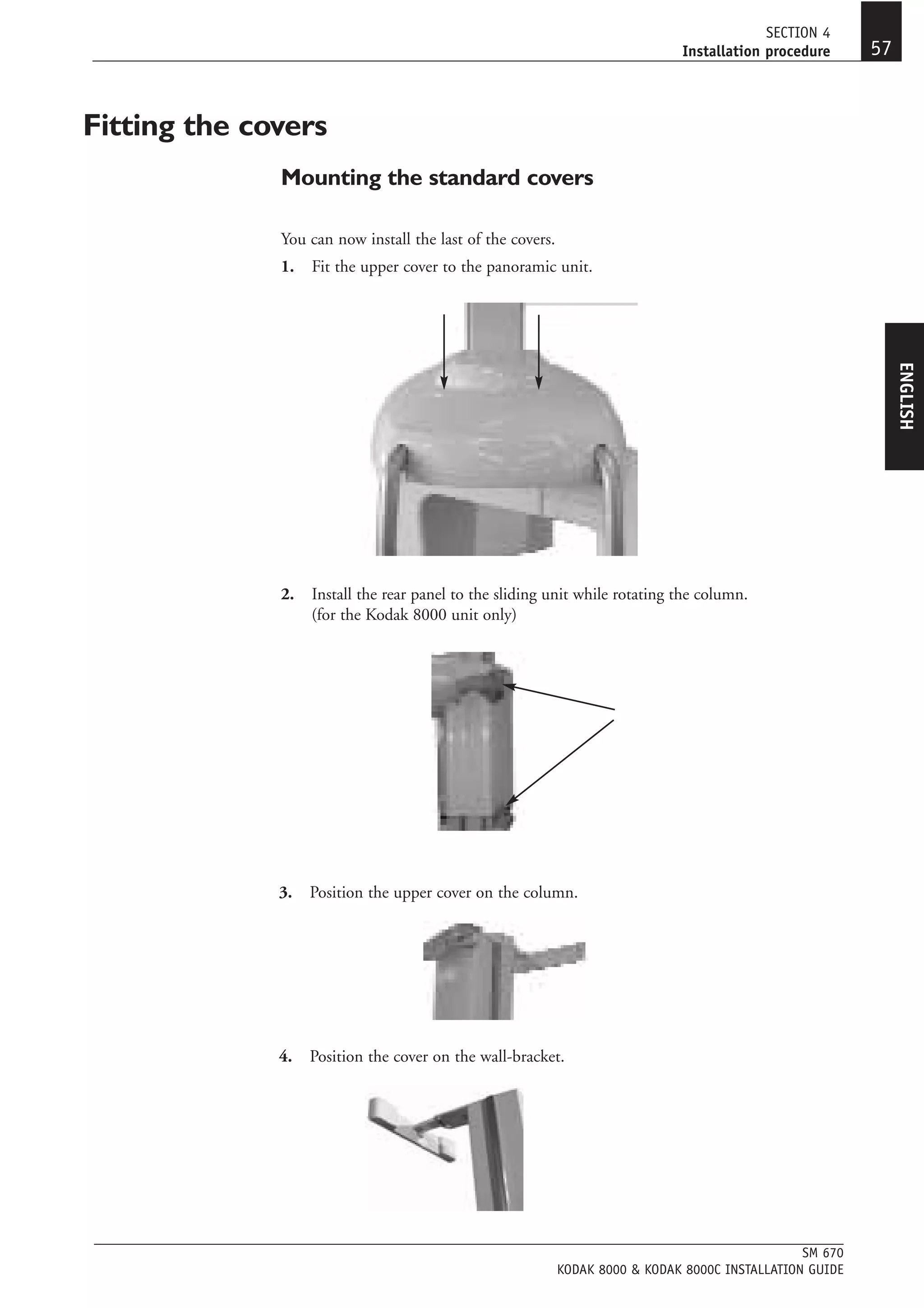
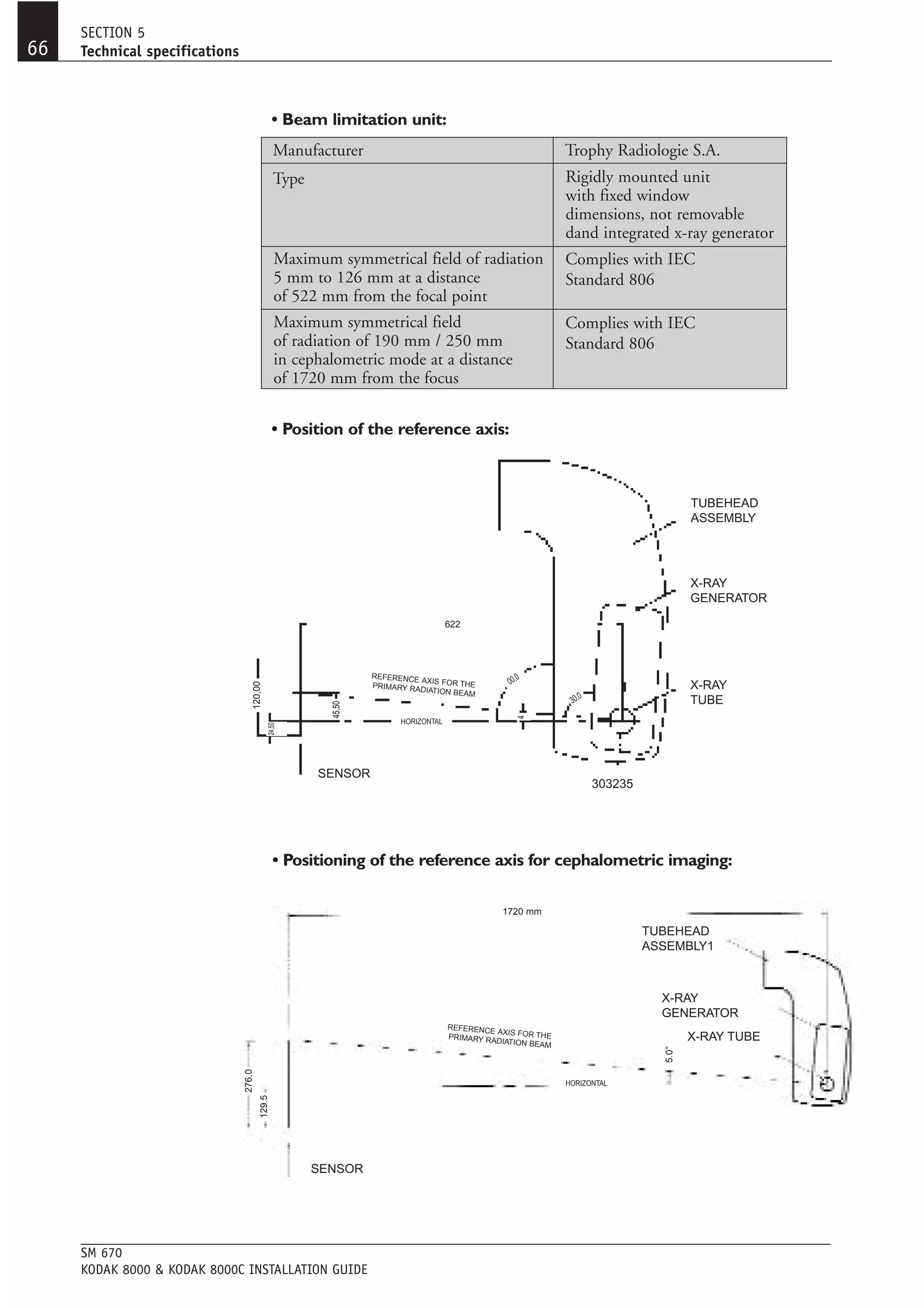
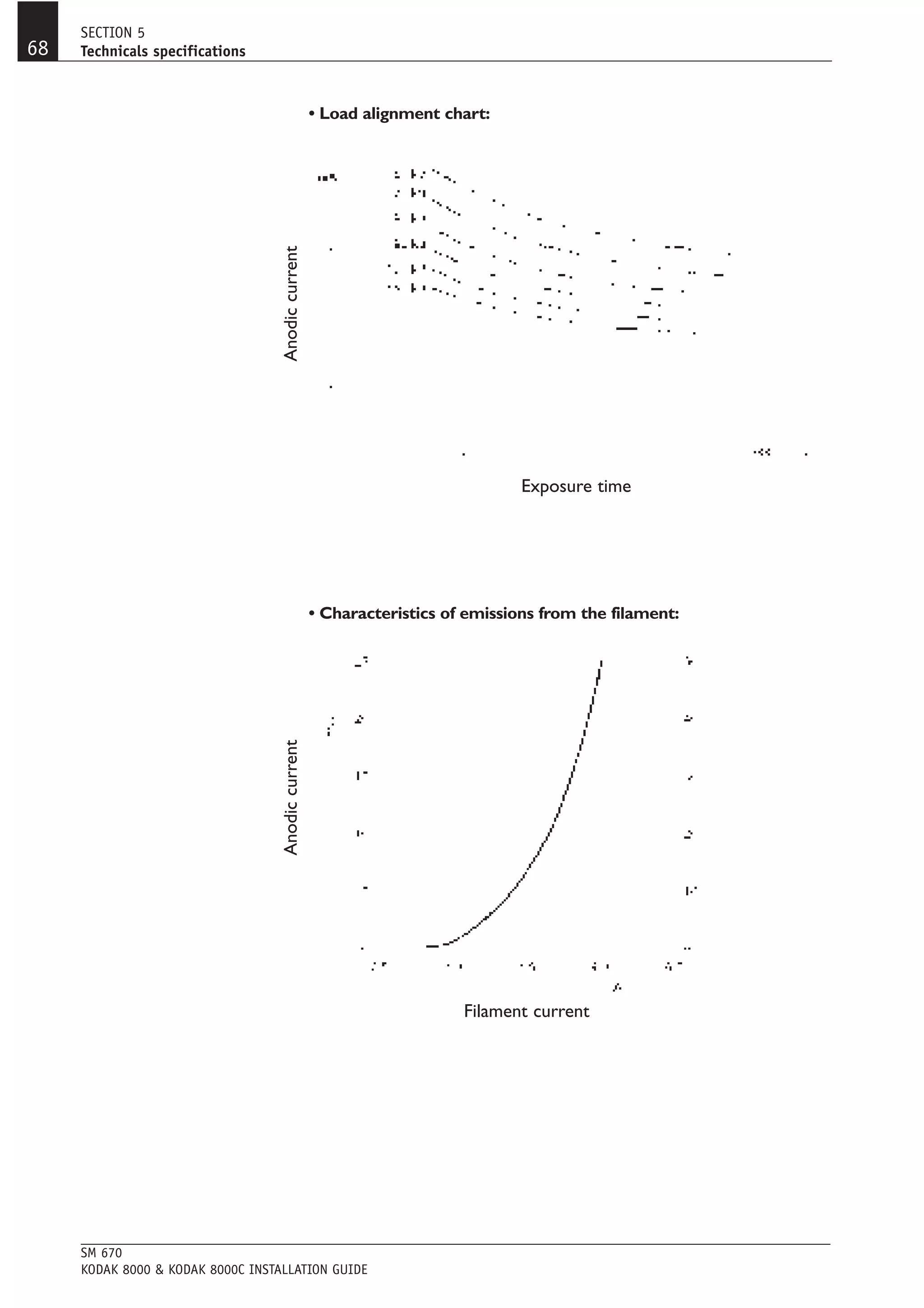
The document provides installation instructions for a Kodak 8000/8000C dental panoramic and cephalometric x-ray unit. It includes dimensional diagrams, packaging details, installation procedure steps, technical specifications, and safety and maintenance information. Installers are instructed to thoroughly read the manual in order to properly set up the unit in compliance with radiation standards and ensure safe operation.
This document is the user manual for Orbiter 2010, a space flight simulator. It provides instructions on installation, an overview of the launch interface and scenario selection, and tutorials for basic flight maneuvers like launching into orbit and docking with space stations. It also describes the different spacecraft modules included, camera controls, instrument displays, and other simulation functions. Appendices provide technical specifications and constants for the solar system modeling in the game. The manual aims to help new users get started with the simulator and learn its interface and basic operations.
Preliminary Design Review (PDR) of Team Garuda at the International Student CanSat competition. Team Garuda secured International Rank 3 out of 40 Teams at the International Student CanSat Competition 2012 at Abilene, TX, USA. Visit http://www.rishidua.com/cansat/ for more information about the team.
This document discusses techniques for closed reduction and casting of fractures. It notes that displaced fractures should be reduced to minimize soft tissue complications. Adequate analgesia and muscle relaxation are critical for successful reduction. The reduction maneuver depends on the fracture location and pattern, and must restore proper length, rotation, and angulation. Longitudinal traction alone may not allow reduction if an intact soft tissue hinge is present. Reproduction of the fracture mechanism is often needed, sometimes requiring angulation beyond 90 degrees. A well-molded three-point cast is necessary to maintain reduction, and a cast with a cast index below 0.7 has been shown to help prevent redisplacement of distal forearm fractures.
Fractures after Knee replacement can be challenging. An algorithmic approach would help manage them better. The presentation defines correct approach towards the same.
The document provides an overview of the Ilizarov ring fixator, including its history, principles, instrumentation, operative techniques, and post-operative management. Some key points:
- The Ilizarov ring fixator was developed in the 1950s in Russia by Gavril Abramovich Ilizarov to treat difficult bone fractures and deformities. It uses a circular external fixator frame connected to bone with wires.
- The fixator works based on the principle of distraction osteogenesis, where bone segments are gradually separated and new bone grows in between.
- Key components of the fixator include rings, wires, rods, nuts, and other connectors. Proper positioning and tensioning of components
The document summarizes guidelines for imaging patients with back pain and sciatica. It finds that advanced imaging like CT and MRI does not change outcomes for acute back pain and sciatica but improves diagnostic confidence. Imaging is generally not recommended for 4-6 weeks to first try conservative treatment unless red flags are present like neurological deficits or signs of infection, tumor, or fracture. Common spinal conditions seen on imaging include disc disease, spinal stenosis from spondylosis, and compression fractures that may be benign or malignant.
사용자 편의성 및 유연성을 고려하여 설계된 소형 PC 시리즈 데스크탑 바코드프린터는 직관적인 라벨 인쇄 솔루션을 제공합니다.
허니웰 PC 시리즈 데스크탑 프린터 모델에는 PC23d (2인치 폭의 감열), PC43d (4인치 폭의 감열), PC43t (4인치 열전사감열) 이 있으며, 제한된 공간에서의 활용도가 높게 설계된 소형 프린터 입니다.
PC 시리즈 바코드프린터는 Wall-Mounted and Battery-Powered 식 등 다양한 배치 옵션으로 신속하게 설치하고 문제없이 사용할 수 있도록 설계되었습니다.
PC 시리즈 프린터에는 범용 아이콘 인터페이스 또는 컬러 LCD가 10 개 언어로 제공되므로 일반 프린터 작업이 간단하고 교육 요구가 줄어 듭니다.
컴퓨터 없이도 USB 썸 드라이브를 사용하여 현장에서 프린터를 구성하고 업데이트 할 수 있습니다.
PC43t 열전사 바코드프린터는 12.7 mm (½ in) 및 25.4 mm (1 in) 리본 코어를 모두 지원합니다.
리본 길이는 300 m (984 ft) 까지 수용함으로써, 빈번한 용지 공급 필요성이 줄어들어 불필요한 시간과 번거로움을 없앨 수 있습니다.
ZSim2를 포함한 포괄적인 명령어 지원을 통해 빠르고, 친숙하며 완벽한 ZPL II® 에뮬레이션 - PC 시리즈로의 업그레이드가 한결 쉬워졌습니다.
Ten-language LCD or intuitive icon graphical user interface.
Simple to use and maintain, with easy one-handed media reloading.
Comprehensive printer command language support, including ZSim2, makes upgrading easy.
Flexible, with user-installable connectivity upgrades and accessories.
This Smart Printer runs apps right inside the printer; you can add keyboards, scanners or other USB peripherals for increased efficiency.
DESCRIPTION
The compact PC series includes both Direct Thermal (PC23d & PC43d) or Thermal Transfer (PC43t) printers designed for self-adhesive labels, nonadhesive tags, linerless, floodcoat, or continuous paper strip roll.
PHYSICAL CHARACTERISTICS
PC43d
Height : 167 mm (6.6 in)
Width : 180 mm (7.1 in)
Depth : 215 mm (8.4 in)
Weight : 1.72 kg (3.8 lbs)
PC43t
Height : 182 mm (7.2 in)
Width : 227 mm (8.9 in)
Depth : 281 mm (11.1 in)
Weight : 2.7 kg (5.9 lbs)
PC23d
Height : 177 mm (6.9 in)
Width : 125 mm (4.9 in)
Depth : 215 mm (8.5 in)
Weight : 1.45 kg (3.2 lbs)
Real-time Clock : Standard (LCD)
Adjustable Gap Sensor : Standard (LCD)
PRINT SPECIFICATIONS
Maximum Label Width : PC43: 118 mm (4.65 in) PC23d: 60 mm (2.36 in)
Maximum Label Length : Standard: 203 dpi - 1727 mm (68 in) 300 dpi - 900 mm (35 in)
Print Direction : Prints text, barcodes and graphics in all four directions
Print Resolution : 8 dots/mm (203 dpi) or 12 dots/mm (300 dpi)
Print Width : PC43: 203 dpi - max. 104 mm (4.1 in) 300 dpi - max. 106 mm (4.2 in) PC23d: 203 dpi - max. 56 mm (2.2 in); 300 dpi - max. 54 mm (2.1 in)
Printing Speed : Selectable up to 8 ips (203.2 mm/ sec) for 203 dpi; 6 ips (152.4 mm/sec) for 300 dpi
MEMORY
Standard : 128 MB Flash, 128 MB RAM (DDR2)
Optional : Up to 32 GB via user USB thumbdrive
INTERFACE
Standard : USB Device Type B connector v.2.0 high speed, USB Host Type A connector v.2.0 high speed
Field Installable: Ethernet 10/100 Mbps module, Dual radio module (802.11 b/g/n and Bluetooth V2.1), USB to Serial adapter (RS-232), USB to Parallel adapter
>하이온아이티
주소 : 서울 금천구 가산디지털2로 165, 1304호 (백상스타타워2차)
대표번호 : 02-2038-0018 / 이메일 : hion@hionit.com
홈페이지 : http://hionsmart.com
This document discusses three common myths about treating AC joint injuries. Myth 1 is that treatment should be based solely on the grade of injury, but the document argues the grade has limited reliability. Myth 2 is that displaced clavicle is the problem, but often it is a scapula injury instead. Myth 3 is that reconstructing the coracoclavicular ligaments is sufficient, but other ligaments and soft tissues are also important. The document recommends evaluating for scapular injury, not rushing to surgery, focusing on rehabilitation initially, and repairing multiple ligaments if surgery is needed.
ARTHROSCOPY AND SPORTS MEDICINE I Dr.RAJAT JANGIR JAIPUR
#aclsurgeryjaipur #aclsurgeryhindia #aclsurgerytaekwondo
Acl reconstruction in jaipur | Acl reconstruction in taekwondo | Acl injury in football player surgery | Acl reconstruction surgery in football | acl surgery | Acl surgery ke baad physiotherapy | Acl surgery in jaipur | acl surgery recovery | Best acl surgeon in jaipur | Best ligament doctor in hindi | Best acl surgeon in india | Meniscus repair surgery in jaipur | Sports injury doctor | Acl injury in football players | Acl injury in taekwondo | acl tear | Best knee surgeon in jaipur
#allinsideacl #internalbrace #drrajatjangir #bestaclsurgeon #aclexpert #bestkneesurgeon
To Know more about ACL Injury, Click the links below:
1. ACL surgery 7 different Techniques we do at our center - "Not single technique best for all"
https://youtu.be/oWkIr8IXvr8
2. Everything about ACL Injury tear surgery in Hindi I
https://youtu.be/bqpjkAkwZ14
3. Best Screw for ACL tear surgery in Hindi
https://youtu.be/1LGpU1NHiIs
4. ACL Injury Tear Surgery Recovery : All your questions & queries solved by Dr.Rajat Jangir
https://youtu.be/SIAPWiMbOqs
5. Partial ACL Tear Surgery or not ! ACL आधा टूटा हो तो क्या करें ?
https://youtu.be/NEJRPKskJTI
6. 5 Symptoms of ACL Injury tear इंजरी के पांच लक्षण ?
https://youtu.be/EXpgy19Jxzw
7. PRP injection therapy in Partial ACL TEARs
https://youtu.be/qyG1EYgS87E
Dr.RAJAT JANGIR(Asso Prof.)
Senior Consultant Arthroscopy and Joint Replacement
(Specialist in Shoulder Knee Hip Surgery)
Ligament and Joints Clinic
67/34 Mansarovar Jaipur
Whatsapp: shorturl.at/gnAEP
Appointment: +91 8104855900
Email: ligamentsurgeon@gmail.com
Google Page: https://g.page/KNEE-Shoulder-SURGERY?...
Facebook: https://www.facebook.com/Ligamentandj...
* Vast experience and specialisation in the field of Arthroscopy and sports surgery.
* M.S. orthopaedics from BJ Medical College, Civil hospital, Ahmedabad
* Fellowship in Arthroscopy and Sports injury with Prof Joon Ho Wang at Samsung Medical Center, South Korea
* Diploma in Sports Medicine from InternationaI Olympic Committee
* Invited as Athlete Medical Doctor at Rio Olympic 2016
* Done Rajasthan's first "All Inside Physeal Preserving ACL reconstruction" in 13 year old Athlete
Dr.Rajat is rated as one of the best orthopedic surgeon with with excellence in Knee Shoulder Arthroscopy surgeries as replacements'
The document discusses adult scoliosis, including classifications, progression, surgical indications, and spinopelvic parameters. It then presents a case study of a 56-year-old male with low back pain and scoliosis who underwent a pedicle subtraction osteotomy at L2 to correct his sagittal imbalance. The case highlights the importance of achieving sagittal balance and proportional lumbar lordosis when surgically treating adult scoliosis.
Dislocation of the knee joint can be a serious injury, especially if there is damage to blood vessels which can lead to limb loss if missed. The knee can dislocate in various positions such as anteriorly, posteriorly, or medially/laterally. Over half of dislocations are anterior or posterior, which have a high risk of popliteal artery injury. Knee dislocations require reduction and splinting, followed by examination and imaging to check for injuries to ligaments, blood vessels, and nerves.
A total knee replacement procedure involves removing damaged cartilage and bone from the knee and replacing them with prosthetic components. The surgeon makes incisions to access the knee joint. Bone is cut from the femur, tibia, and patella. Trial components are fitted to ensure proper size and alignment. Cement is used to secure the permanent metal and plastic implants. The wound is closed and dressed. The new knee joint allows improved function and pain relief.
Current concepts in the management of shoulder instabilityPonnilavan Ponz
This document discusses the current concepts in the management of shoulder instability. It covers the causes, classifications, investigations, and treatment options for shoulder instability. For treatment, it emphasizes the importance of a systematic approach that considers the patient's age, activity level, and nature of the soft tissue and bony injuries. Non-operative treatments include physiotherapy, while operative options depend on the specific injuries and may include arthroscopic bankart repair, open latarjet procedure, remplissage, or capsular shift procedures. The goal of treatment and rehabilitation is to return the patient to their prior level of function and activity.
Four corner arthrodesis a retrospective reviewpersonalp
(1) The document reviews a retrospective study of 10 cases of four corner arthrodesis performed between 2001-2004 to treat various stages of scapholunate advanced collapse (SLAC) and scaphoid nonunion advanced collapse (SNAC) arthritis.
(2) Results found a 90% union rate but intermediate outcomes were poor compared to literature, with most patients reporting only moderate pain relief and 40% average range of motion recovery.
(3) The conclusion discusses that patient factors like the specific stage of arthritis and degree of wrist extension may determine whether four corner fusion or alternative procedures like proximal row carpectomy or scaphoid resection are most appropriate in individual cases.
This document summarizes the treatment of femur shaft fractures. It describes the typical causes, presentation, and pathoanatomy of femur fractures. Conservative treatment options include traction with splints or casts. Operative options are closed intramedullary nailing or plating with screws. Treatment decisions depend on factors like age, location, and presence of wounds. Complications can include shock, fat embolism, nerve injuries, infection, malunion, and knee stiffness.
The document discusses shoulder separations, providing details on:
1) The types of shoulder separations from Grade I to VI based on the Rockwood scale and the ligament damage involved.
2) The symptoms of shoulder separations including pain, swelling, deformity.
3) The treatment options which include resting, icing, anti-inflammatory medications, physical therapy for mild cases or surgery to repair damaged ligaments for more severe cases.
4) There is debate around treatment of type III separations, as studies have shown non-surgical and surgical options can both have good outcomes, with factors like the patient's activity level determining the approach.
The document discusses the anatomy and physiology of the tibial epiphysis and physis. It describes the zones of the growth plate including the reserve, proliferative, and hypertrophic zones. Physeal fractures are discussed and classified using the Salter-Harris system. Type I fractures involve the hypertrophic zone while more severe types involve the epiphysis or metaphysis. Management of physeal injuries aims to reduce the fracture while avoiding further damage to the growth plate.
This document summarizes the presentation on clavicle fractures by Dr. K Maneesh Chandra. It discusses the mechanisms of injury, physical exam findings, imaging modalities, anatomy, treatment options and management of complications for clavicle fractures in infants, children and adults. Surgical treatment involves open reduction and internal fixation with plates or screws while non-surgical treatment uses sling immobilization. Complications are addressed and factors influencing treatment choice are outlined.
Total Hip replacement for Ankylosing Spondylitis: Planning & Execution Vaibhav Bagaria
Performing Total Hip replacement in Ankylosing Spondylitis requires a well thought of strategy. Preoperative planning, Inventory ordering, positioning, cup and stem orientation all play a role.
This document provides an overview of hip imaging and common hip pathologies. It discusses early onset osteoarthritis, hip dysplasia, femoroacetabular impingement, labral tears, cartilage damage, and tendon injuries that can be seen on hip imaging. The document outlines techniques for evaluating the acetabulum, femoral head, labrum, cartilage and surrounding soft tissues. It also notes that many asymptomatic individuals may have incidental findings on hip imaging and that the level of activity plays a role in determining which morphological abnormalities become symptomatic.
This document provides an overview of intramedullary nailing principles. It discusses the history and evolution of intramedullary nails from wooden sticks and ivory pegs used in the 16th century to modern nails like the Russell-Taylor nail. It covers nail types, biomechanics, insertion techniques, and key design considerations like diameter, cross-section shape, curves, and locking mechanisms. The goal of intramedullary nailing is to provide stable internal splinting of long bone fractures through closed fixation techniques.
The document discusses fractures of the hand, including:
- The anatomy of the hand bones and joints.
- Common fracture patterns of the metacarpals, phalanges, and thumb bones.
- Clinical assessment including signs, symptoms, and imaging for hand fractures.
- Treatment approaches such as closed reduction, percutaneous pinning, and open reduction based on the fracture type and stability.
Diagnosis and Treatment of Low Back Pain Ade Wijaya
This document summarizes guidelines for diagnosing and treating low back pain from the American College of Physicians and American Pain Society. It recommends clinicians conduct a focused history and physical to classify back pain and assess psychosocial risk factors. Imaging and testing are not routinely needed for nonspecific back pain but may be for severe or progressive neurological symptoms. Options for acute back pain treatment include medications, spinal manipulation, and staying active. Chronic back pain may be helped by interdisciplinary rehabilitation, exercise, acupuncture, massage, spinal manipulation, yoga, or cognitive-behavioral therapy.
This document discusses shoulder instability, including traumatic and atraumatic causes. It presents three case studies to demonstrate different types of instability: 1) a rugby player with recurrent anterior dislocations requiring surgical repair for bony lesions; 2) a drama student with recurrent posterior subluxations and normal imaging, indicating a motor control issue; and 3) a gymnast with multidirectional instability and hyperlaxity who may benefit from capsular plication. The document outlines the Stanmore classification system for shoulder instability (Polar types I-III) and factors to consider in surgical versus rehabilitation management depending on the specific instability pattern.
The document discusses graft fixation options in ACL reconstruction. It notes that fixation is the weakest link in the early postoperative period and that tibial fixation carries a greater risk of failure. Interference screws provide the gold standard for fixation but tunnel widening remains a concern. The ideal fixation is strong, stiff, and secure to avoid graft slippage and interference with healing while allowing revision. Aperture fixation and hybrid techniques may improve outcomes over suspensory fixation alone. Rehabilitation must also account for the biomechanical strengths and weaknesses of the fixation method used.
The Future of Orthobiologics in Trauma ProceduresApril Bright
Based on his clinical research interests in utilization of Alpha-BSM bone graft substitute and OP-1 recombinant BMP in the repair of fractures, Daniel N. Segina, M.D., outlined opportunities and challenges for surgeons and device companies in biologic development. To make his case, Dr. Segina reviewed the spectrum of orthobiologics used in trauma cases today, shared perspective on what is and isn’t working and forecasted the future of regenerative medicine.
The document is a user manual for the SmartOTDR 100 Mainframe handheld OTDR. It provides instructions on safety, starting up the device, configuring settings, using the integrated power meter and visual fault locator, scope feature, connectivity options, and remote control capabilities. The manual guides the user on unpacking, charging batteries, making measurements, storing results, and connecting to other devices via Bluetooth, WiFi, Ethernet, or cloud storage for remote operation and file sharing.
This document provides manuals and instructions for ABB general machinery drives. It includes:
1. A list of related manuals delivered with ABB drives in printed or PDF format, including the ACS355 user's manual.
2. An overview of the ACS355 user's manual, which covers safety, mechanical installation, electrical installation, start-up and control.
3. Details about additional option manuals and maintenance manuals available from ABB.
This document provides manuals and guides for ABB general machinery drives. It includes:
1. A list of related manuals delivered with ACS355 drives in printed or PDF format, including the ACS355 user's manual.
2. Details about additional option and maintenance manuals available from ABB in PDF format.
3. An overview of the contents and structure of the ACS355 user's manual, including safety information, mechanical installation instructions, electrical planning, start-up procedures and more.
This document is the user's manual for ACS310 drives. It begins with a table of contents and list of related manuals. The introduction provides an overview of the manual's purpose and contents. It then covers the drive's operation principle, hardware description, type designation label and installation. Subsequent sections provide planning guidance for the electrical installation, including selecting cables and their routing. It also provides recommendations for protecting the drive and related components.
This document is the user guide for the GENESYS 10S UV-Vis spectrophotometer. It provides instructions on setup, operation, and maintenance of the instrument. The guide covers topics such as connecting accessories, initializing cell holders, taking absorbance and transmittance measurements, performing concentration measurements using calibration curves, and managing stored test methods. It also provides contact information for technical support.
The document provides information about renting, buying, financing, and servicing test equipment from TMG. It includes a disclaimer stating that trademarks appearing in the PDF are owned by their respective companies. The second page describes the JDSU 2000 Platform, a handheld, modular tester designed for fiber network construction, turn-up, and maintenance. It has a user manual and complies with the WEEE Directive for electronic waste.
- The document is the user manual for the CL3108 / CL3116 LCD KVM switch, which provides instructions on installation, operation, and specifications of the device.
- It includes information on FCC compliance, a list of package contents, diagrams of the front and rear panels, instructions for hardware setup and basic operation, and descriptions of the on-screen display functions.
- The manual is intended to guide users on safely installing and using the KVM switch to control multiple computers from a single console.
This document provides service information for the Acer Aspire one Series notebook, including disassembly and reassembly instructions. It contains 7 sections and covers removing and replacing external modules like the battery and keyboard, as well as internal components such as the LCD module, mainboard, hard drive, and other parts. Precautions are given to properly conduct disassembly and reassembly procedures.
This document is the user guide for Ubiquiti's airFiber AF5 and AF5U 5 GHz full duplex point-to-point gigabit radios. The guide contains 10 chapters that describe the product overview, installation, configuration, settings, and specifications of the radios. It provides instructions for planning the wireless link, installing the hardware, connecting power and Ethernet, aligning the antennas, and navigating the airFiber configuration interface to set up and manage the wireless network settings.
This document is the user's guide for the Xplore Technologies XSLATE B10 tablet. It provides important safety information and instructions for using and maintaining the tablet. The guide covers system overview, getting started, using the touch screen and EMR pen, maintaining the device by caring for components like the display screen, and troubleshooting. It also includes specifications, regulatory notices, and environmental policies.
The document provides important safety information and instructions for installing, configuring, operating, and maintaining Integrated Display Industrial Computers with Keypad from Rockwell Automation. It contains details on pre-installation requirements, installation procedures including mounting and connecting power, basic operating guidelines, and troubleshooting. The document was revised to add new sections, update existing sections, and clarify instructions throughout.
This document provides information about an EtherCAT communication module used for networking and remote servicing of machines. It describes the features and functions of the communication module, including safety instructions. It also provides technical specifications and information about configuration, installation, commissioning, and data transfer processes. The document is intended to supplement other documentation for standard devices and provide details on using the communication module with a host system over EtherCAT.
This document provides an overview and user manual for the MicroLogix 1100 programmable controller and 1762 expansion I/O from Rockwell Automation. It describes the hardware components, installation procedures, wiring requirements, communication options, and programming interface. Safety guidelines and considerations are also discussed. The manual is intended for users applying and installing the MicroLogix 1100 controller and I/O.
This document provides the user's manual for ABB component drives ACS150 drives ranging from 0.37 to 4 kW (0.5 to 5 hp). It includes a list of related manuals, a table of contents, and sections covering safety, an introduction to the manual, the operation principle and hardware description, mechanical installation, planning the electrical installation, and electrical installation. The manual provides instructions and specifications for installing, commissioning, and operating the ACS150 drives.
- The document discusses copyright and trademark information for Xerox and other companies. It lists copyrighted materials, trademarks, and logos that are not to be reproduced without permission.
- Parts of the printer are described, including views of the exterior and interior components. Optional finishers that can be added to the printer are also depicted.
- Standard features, configurations, and options for the printer are provided. The control panel layout is shown and its functions are explained.
This document provides information related to the hp LaserJet 1150 and 1300 series printers, including:
- An overview of the printer hardware, firmware, and specifications
- Instructions for installation, operation, and maintenance including loading media, replacing parts, and cleaning
- Descriptions of the printer's functions such as the image formation system, paper feed system, and basic sequence of operation
- Safety and regulatory information as well as details on warranties and print cartridges
This document is the user's manual for the 475 Field Communicator. It provides instructions on operating the device safely and gives an overview of its features. These include communicating with HART and fieldbus devices, managing device configurations, battery and accessory information, and troubleshooting. The manual contains sections covering basics, HART and fieldbus functionality, maintenance, and specifications.
This document is the user's guide for the SmartClass Ethernet Tester. It contains information about features and capabilities, preparation for use, navigating the user interface, instrument settings, and Ethernet testing functions. The guide includes sections on exploring the front panel, powering the tester on and off, menu screens, data entry, results screens, and using the keypad. It also provides instructions for cable diagnostics, optical power measurement, initializing links, and specifying settings for Ethernet and payload tests.
Cell Therapy Expansion and Challenges in Autoimmune DiseaseHealth Advances
There is increasing confidence that cell therapies will soon play a role in the treatment of autoimmune disorders, but the extent of this impact remains to be seen. Early readouts on autologous CAR-Ts in lupus are encouraging, but manufacturing and cost limitations are likely to restrict access to highly refractory patients. Allogeneic CAR-Ts have the potential to broaden access to earlier lines of treatment due to their inherent cost benefits, however they will need to demonstrate comparable or improved efficacy to established modalities.
In addition to infrastructure and capacity constraints, CAR-Ts face a very different risk-benefit dynamic in autoimmune compared to oncology, highlighting the need for tolerable therapies with low adverse event risk. CAR-NK and Treg-based therapies are also being developed in certain autoimmune disorders and may demonstrate favorable safety profiles. Several novel non-cell therapies such as bispecific antibodies, nanobodies, and RNAi drugs, may also offer future alternative competitive solutions with variable value propositions.
Widespread adoption of cell therapies will not only require strong efficacy and safety data, but also adapted pricing and access strategies. At oncology-based price points, CAR-Ts are unlikely to achieve broad market access in autoimmune disorders, with eligible patient populations that are potentially orders of magnitude greater than the number of currently addressable cancer patients. Developers have made strides towards reducing cell therapy COGS while improving manufacturing efficiency, but payors will inevitably restrict access until more sustainable pricing is achieved.
Despite these headwinds, industry leaders and investors remain confident that cell therapies are poised to address significant unmet need in patients suffering from autoimmune disorders. However, the extent of this impact on the treatment landscape remains to be seen, as the industry rapidly approaches an inflection point.
Muktapishti is a traditional Ayurvedic preparation made from Shoditha Mukta (Purified Pearl), is believed to help regulate thyroid function and reduce symptoms of hyperthyroidism due to its cooling and balancing properties. Clinical evidence on its efficacy remains limited, necessitating further research to validate its therapeutic benefits.
TEST BANK For An Introduction to Brain and Behavior, 7th Edition by Bryan Kol...rightmanforbloodline
TEST BANK For An Introduction to Brain and Behavior, 7th Edition by Bryan Kolb, Ian Q. Whishaw, Verified Chapters 1 - 16, Complete Newest Versio
TEST BANK For An Introduction to Brain and Behavior, 7th Edition by Bryan Kolb, Ian Q. Whishaw, Verified Chapters 1 - 16, Complete Newest Version
- Video recording of this lecture in English language: https://youtu.be/kqbnxVAZs-0
- Video recording of this lecture in Arabic language: https://youtu.be/SINlygW1Mpc
- Link to download the book free: https://nephrotube.blogspot.com/p/nephrotube-nephrology-books.html
- Link to NephroTube website: www.NephroTube.com
- Link to NephroTube social media accounts: https://nephrotube.blogspot.com/p/join-nephrotube-on-social-media.html
8 Surprising Reasons To Meditate 40 Minutes A Day That Can Change Your Life.pptxHolistified Wellness
We’re talking about Vedic Meditation, a form of meditation that has been around for at least 5,000 years. Back then, the people who lived in the Indus Valley, now known as India and Pakistan, practised meditation as a fundamental part of daily life. This knowledge that has given us yoga and Ayurveda, was known as Veda, hence the name Vedic. And though there are some written records, the practice has been passed down verbally from generation to generation.
Local Advanced Lung Cancer: Artificial Intelligence, Synergetics, Complex Sys...Oleg Kshivets
Overall life span (LS) was 1671.7±1721.6 days and cumulative 5YS reached 62.4%, 10 years – 50.4%, 20 years – 44.6%. 94 LCP lived more than 5 years without cancer (LS=2958.6±1723.6 days), 22 – more than 10 years (LS=5571±1841.8 days). 67 LCP died because of LC (LS=471.9±344 days). AT significantly improved 5YS (68% vs. 53.7%) (P=0.028 by log-rank test). Cox modeling displayed that 5YS of LCP significantly depended on: N0-N12, T3-4, blood cell circuit, cell ratio factors (ratio between cancer cells-CC and blood cells subpopulations), LC cell dynamics, recalcification time, heparin tolerance, prothrombin index, protein, AT, procedure type (P=0.000-0.031). Neural networks, genetic algorithm selection and bootstrap simulation revealed relationships between 5YS and N0-12 (rank=1), thrombocytes/CC (rank=2), segmented neutrophils/CC (3), eosinophils/CC (4), erythrocytes/CC (5), healthy cells/CC (6), lymphocytes/CC (7), stick neutrophils/CC (8), leucocytes/CC (9), monocytes/CC (10). Correct prediction of 5YS was 100% by neural networks computing (error=0.000; area under ROC curve=1.0).
4. 3
Congratulations on your purchase of a Kodak dental systems. Thank you for your
confidence in our products and we will do all in our power to ensure your
complete satisfaction.
You now have the Installation Guide for the Kodak 8000 / Kodak 8000C digital
panoramic and cephalometric unit. We recommend that you thoroughly
familiarize yourself with this Guide in order to make the most effective use of your
system.
The information contained in this Manual may be subject to modification
without notice, justification or notification to the persons concerned.
No part of this Guide may be reproduced without the express permission of
Eastman Kodak Company.
ENGLISH
The brand names and logos reproduced in this Guide are copyright.
RVG RadioVisioGraphie, Digipan, Trophy, Trophy Radiologie and the TR logo are registered trade
marks of Eastman Kodak Company. Microsoft, MS-DOS and Windows are trade marks or registered
trade marks of the Microsoft Corporation. All other names or products referred to in this document
are only used for the purpose of identification and may be the trade marks or registered trade marks
of their respective owners.
The RVG technology is the subject of an international patent registered by Eastman Kodak
Company.
This document was originally written in French.
Revision date: 10/2004
The Kodak 8000 unit complies with Directive 93/42/CEE relating to medical device.
SM 670
KODAK 8000 & KODAK 8000C INSTALLATION GUIDE
7. Notes for the User 7
Notes for the User
X-rays are not innocuous and can be dangerous if not used properly. Therefore, the
instructions and warnings contained in this Manual must be carefully followed.
As a manufacturer of radiology units which conform to the most stringent
radiological protection standards in force throughout the world, Eastman Kodak
Company’s know-how guarantees the maximum degree of protection against
radiation hazards.
Nonetheless, you are handling a radiology unit which is specially designed to emit
a dose of x-rays in order to carry out a medical diagnosis with the aid of a Eastman
Kodak Company digital imaging system (exclusive patent).
ENGLISH
The room in which your radiology unit is to be installed must comply with all
official regulations applicable to protection against radiation.
Your dealer will be pleased to assist with the initial use of your radiology unit and
will supply any relevant information you may require.
The "WARNING" and "IONIZING RADIATION" symbols signify:
"WARNING: IONIZING RADIATION".
To install, operate and service the unit, follow the instructions contained in this
Manual.
SM 670
KODAK 8000 & KODAK 8000C INSTALLATION GUIDE
8. 8 Warnings and safety instructions
Warnings and safety instructions
CAUTION Laser radiation. Do not stare into beam.
Class 2 laser product
Maximum output power: 1 mW, 650 nm
IEC60825-1 :1993+A1 :1997+A2 :2001
This unit emits laser radiation.
For maximum safety, advise the patient not to look at the beam.
Before illuminating the beams, lower the Frankfurt plane beam to the lowest level.
While making adjustments, ensure that the beam is not directed into the patient’s
eyes.
DANGER This is an electrical unit. Do not expose it to water spray.
Such action may cause an electric shock or a malfunction of the unit.
WARNING The user is responsible for the operation and maintenance of this unit.
This unit must only be operated by legally qualified persons.
The cover of the unit must not be opened by the operator.
When necessary, inspection and maintenance operations should only be carried out
by an approved Eastman Kodak Company technician.
WARNING This unit must be installed in x-ray room which complies with current
installation standards.
From this location, visual or audio communication must be maintained with the patient,
together with access to the control interface during exposure.
WARNING The Kodak 8000 unit has been designed to comply with European and
international medical standards. In order to ensure conformity, the PCI interface board
must be installed in a computer configuration which conforms to IEC 950 Standard.
The PC and the peripheral equipment connected to it must not be located in the
immediate vicinity of the patient, thus at least 1.5 m from the panoramic unit.
For details of the data processing system (PC and screen), refer to the installation
manuals for your computer. Sufficient clear space must be left around the CPU in order
to ensure that it is properly ventilated.
In order to obtain maximum image quality and visual comfort, the screen should be
positioned so as to avoid direct light reflections (internal or external lighting).
WARNING Do not operate the unit if there is the threat of an earthquake.
Following an earthquake, ensure that the unit is operating satisfactorily before
using it again.
Failure to observe this precaution may expose patients to hazards.
SM 670
KODAK 8000 & KODAK 8000C INSTALLATION GUIDE
9. Warnings and safety instructions 9
WARNING X-ray equipment can be hazardous to patients and the operator if the exposure
safety factors and operating instructions are not observed.
WARNING Do not place objects within the field of operation of the unit.
WARNING Ensure that the patient and the operator are wearing aprons to protect them
against X-rays.
Ensure that any parts of the unit which may come into contact with the patient and the
ENGLISH
operator have been disinfected after each patient has been exposed to X-rays.
While adjusting the height of the unit, the operator must ensure that the patient is kept clear
of the mechanism.
When the unit is not in use, ensure that the ON/OFF switch is set to OFF (O).
If the unit develops a fault, switch it off (O) and display a notice ‘Unserviceable’.
WARNING To dispose of the unit and/or its components, contact our representatives or our
Company.
WARNING Do not rotate the arm unit by hand as this may damage the unit.
WARNING The operator must ask the patient to refrain from moving during the entire period
of exposure.
WARNING The operator must ask the patient to refrain from moving until the ARM UNIT has
stopped moving and throughout the RESET movement.
WARNING Equipment not suitable for use in the presence of a flammable anaesthetic
mixture with air or with oxygen or nitrous oxide.
SM 670
KODAK 8000 & KODAK 8000C INSTALLATION GUIDE
10. 10 Responsibility and Warranty
Responsibility and Warranty
Eastman Kodak Company guarantees for a period of two years starting from the
invoice date of the product, that it does not contain any defects, in the materials
used or at manufacturing level, and this only when used and maintained correctly.
Only the damage affecting the products themselves will be taken into account, the
client can in no case claim damage compensation if it does not purely concern the
products themselves provided that this exclusion of responsibility does not infringe
any legal measures.
This warranty does not cover damages and faults due to accident, incorrect usage,
improper use, negligence or wear and tear due to normal use.
Eastman Kodak Company can therefore not be held liable for the consequences
resulting from the non-application of the instructions contained in the installation
and user manuals, namely bodily harm, profit loss, operational interruptions, data
loss, loss of a financial nature or any direct or indirect damage.
If, on the other hand, the product is proven to be faulty with regards to materials
or manufacturing, the responsibility will lie with Eastman Kodak Company but
will be limited to the repair of the aforementioned at its own facilities or, at the
discretion of Eastman Kodak Company, of its replacement. Regardless of the
solution chosen by Eastman Kodak Company, the client will need to return the
faulty product at his own expense. It has clearly been established that except for
the repair of the product where it will assume the cost of spare parts and labour,
the Eastman Kodak Company will only take on the costs of return to the delivery
address initially communicated by the client.
Eastman Kodak Company will have the possibility to examine any presumed
defect.
Clients are not entitled to delay the payment of their bills, nor to any financial
deductions by way of the products reputed to be faulty.
Due to the continuous development of its products, Eastman Kodak Company
reserves the right to amend at any time the manual and products mentioned
therein, without justification or having to notify the people involved.
Our products are guaranteed ex-works in their original packaging. Eastman Kodak
Company cannot be held liable for damages resulting from transportation
conditions.
Consumable spares, software and accessories are excluded from the warranty.
SM 670
KODAK 8000 & KODAK 8000C INSTALLATION GUIDE
11. SECTION 1
Dimensional diagrams 11
SECTION 1
DIMENSIONAL DIAGRAMS
General arrangement views
CAUTION If the Kodak 8000 unit is planned to be upgraded with a digital cephalometric
ENGLISH
attachment, please refer to the depth dimension mentioned in italics on the diagrams. The
fixing hole of the screw will indeed be farthest from the wall to allow the mounting of the
cephalometric attachment.
NOTE The standard version of the unit has an overall height of 2315 mm (91.25 inches).
A unit with an overall height of 2200 mm (86.6 inches) is available by special order.
Overall height of the unit
SM 670
KODAK 8000 & KODAK 8000C INSTALLATION GUIDE
12. SECTION 1
12 Dimentional diagrams
Width and depth of the unit
Dimensions of the column and attaching parts
SM 670
KODAK 8000 & KODAK 8000C INSTALLATION GUIDE
13. SECTION 1
Dimensional diagrams 13
Minimum/maximum height of the chin rest
ENGLISH
Installation drawing
Standard Installation
A/ Access to the right of the unit
NOTE
These installation
drawings show the
recommended
configurations to
allow optimal access
to the unit.
SM 670
KODAK 8000 & KODAK 8000C INSTALLATION GUIDE
14. SECTION 1
14 Dimentional diagrams
B/ Access to the left of the unit
Installation at an angle
A/ Access to the right of the unit
SM 670
KODAK 8000 & KODAK 8000C INSTALLATION GUIDE
15. SECTION 1
Dimensional diagrams 15
B/ Access to the left of the unit
ENGLISH
SM 670
KODAK 8000 & KODAK 8000C INSTALLATION GUIDE
16. SECTION 1
16 Dimentional diagrams
Installing the cephalometric arm on the right side
Warning
The dimensions shown are the recommended dimensions for optimal installation
and easy access to the unit for both maintenance and day-to-day use.
These dimensions are valid for an optimized installation, i.e., one in which the
arm is being installed in the same side as the access to the Kodak 8000 unit in
place. For example, for a Kodak 8000 unit with right-hand access, we recommend
that the cephalometric arm be installed on the right-hand side. All access to the
unit can then be made on the same side, which will save space in the room.
If you are installing the arm on a different side from that used to access the
panoramic unit, more space will be required in the room. It will be the installer’s
responsibility to ensure that the equipment is properly installed.
NOTE Provide for adequate space to the rear of the cephalostat sensor to ensure easy
access for maintenance purposes.
NOTE The Kodak 8000C unit cannot be installed in a corner.
A/ Overall height of the unit
NOTE
These installation drawings
show the recommended
configurations to allow
optimal access to the unit.
SM 670
KODAK 8000 & KODAK 8000C INSTALLATION GUIDE
17. SECTION 1
Dimensional diagrams 17
B/ Width and depth of the unit
➠
➠
ENGLISH
➠
Installing the cephalometric arm on the left side
A/ Overall height of the unit
SM 670
KODAK 8000 & KODAK 8000C INSTALLATION GUIDE
18. SECTION 1
18 Dimentional diagrams
B/ Width and depth of the unit
➠
➠
➠
Optional base plate
A mounting base is available as an option for installation without drilling into the
floor. This base plate can be used with the Kodak 8000 unit or the Kodak 8000C
unit.
For installation of a Kodak 8000 unit, wall mounting the unit is STRONGLY
RECOMMENDED in addition to use of the base plate to ensure optimal
stability.
For installation of a Kodak 8000C unit, wall mounting is REQUIRED, even if
the unit is mounted on a base plate as well.
Dimensions: 900 x 600
Gross weight: 62 kg
Net weight: 50 kg
Reference: CG351
SM 670
KODAK 8000 & KODAK 8000C INSTALLATION GUIDE
19. SECTION 1
Dimentional diagrams 19
• Dimensions of the base plate of the Kodak 8000 unit
ENGLISH
• Overall height of the unit including the base plate
SM 670
KODAK 8000 & KODAK 8000C INSTALLATION GUIDE
20. SECTION 1
20 Dimentional diagrams
• Dimensions of the column and attaching parts
SM 670
KODAK 8000 & KODAK 8000C INSTALLATION GUIDE
21. SECTION 2
Packaging 21
SECTION 2
PACKAGING
Standard packing
Box # 1: Head assembly Box # 2: Column assembly
ENGLISH
Dimensions (cm) 71 (D) x 123 (L) x 125 (H) 35 (D) x 240 (L) x 47 (H)
Weight 120 kg 80 kg
Cephalometric option
Box # 3: Cephalostat unit
Dimensions (cm) 90 (D) x 1640 (L) x 610 (H)
Weight 80 kg
Description of the components
Box # 1: Head Assembly
The box contains various items:
x Separate components
y One box containing the technical accessories
z One box of ‘Accessories’
SM 670
KODAK 8000 & KODAK 8000C INSTALLATION GUIDE
22. SECTION 2
22 Packaging
Separate components
Product Code Description Quantity
CG 333 Panoramic head assembly 1
HY 273 Upper column cover 1
LV 098 Handswitch 1
Mounting hook for
HY 173 1
handswitch
CG 329 Connection box 1
Extension for the connection
CP 906 1
box
Technical accessories
Product Code Description Quantity
CJ 648 PCI board 1
LO 096 Masking floppy disk 1
SM 670
KODAK 8000 & KODAK 8000C INSTALLATION GUIDE
23. SECTION 2
Packaging 23
LO Software
1
150KDIS and drivers
LO 073 Test report 1
Centering screen tool for
ENGLISH
OT 001 1
maintenance
Ball phantom for technical
OT 011 tests and for preventive and 1
NOTE
A 3-meter mains power corrective maintenance
cord with a European
plug is also supplied
with the unit. ZN 013
Alen keys 2
ZN 014
One box of “accessories”
Product Code Description Quantity
JR 265 Panoramic chin rest 1
(supplied fitted to the unit)
JR 263 Chin rest for maxillary sinus 1
sinus maxillaires
Nasal support for TMJ
JR 264 1
program
HY 048 Standard bite block 6
SM 670
KODAK 8000 & KODAK 8000C INSTALLATION GUIDE
24. SECTION 2
24 Packaging
Bite block for ‘edentulous
HT 182 2
patients’
FC 020 Bite block support 2
Plastic hygienic protective
BD 103 1
sleeves (box of 500 items)
Box # 2: Packaging for the Column Assembly
Product Code Description Quantity
CG 298 Column assembly 1
CG 332 Wall mounting bracket 1
CG 492 Wall-bracket cover 1
SM 670
KODAK 8000 & KODAK 8000C INSTALLATION GUIDE
25. SECTION 2
Packaging 25
Box # 3 (Optional): Cephalostat unit
Separate components
Product Code Description Quantity
/ Cephalostat arm 1
ENGLISH
/ Cephalostat head 1
HY 306 Cover of the secondary arm 1
CG 382
+ Ear rods 2
CG 383
Accessories
Product Code Description Quantity
CP 278 SUB-D9/25-pin adapter 1
Cephalometric masking
/ 1
floppy disk
/ Bag of screws 1
SM 670
KODAK 8000 & KODAK 8000C INSTALLATION GUIDE
26. SECTION 3
Checking the premises before installation 27
SECTION 3
CHECKING THE PREMISES
BEFORE INSTALLATION
Standards
ENGLISH
Compliance with standards:
Check that the room in which the unit is to be installed complies with the
electrical standards and the radiological protection standards in force in the
country concerned.
Mechanical
Position of the unit in the room:
Prior to placing the order and before installation, carefully check the position of the
panoramic unit in the room.
We recommend that the unit should be installed along a wall, but a minimum
amount of space must be provided to allow easy access to the patient or by the
maintenance technician.
The wall bracket allows an optimal installation in a corner of the room.
Minimum width of the door:
The width of the door must be at least 80 cm (31.5”).
Minimum height of the ceiling:
The overall height of the unit is 230 cm (90.5”). We recommend that the
minimum height of the ceiling should be 240 cm (94.5”).
If space is at a premium, the height of the column can be adjusted at the factory if
specifically requested on the order.
Strength of the wall:
The wall must be capable of withstanding an extraction force of 150 kPa at each
point of attachment.
Depending on the type of wall, it is the responsibility of the installer to choose a
fixing system which is capable of withstanding an extraction force of 150 kPa
applied to each fixing.
Load-bearing capacity of the floor:
The load-bearing capacity of the floor should be 500 kg/m2.
The floor must be solid and flat.
SM 670
KODAK 8000 & KODAK 8000C INSTALLATION GUIDE
27. SECTION 3
28 Checking premises before installation
Electrical
Required electrical specifications:
Nominal voltage* Maximum line
Minimum Maximum
(no load) current
110 V 99 V 143 V 20 A
130 V 99 V 143 V 20 A
230 V 207 V 264 V 10 A
240 V 207 V 264 V 10 A
* The units are supplied for operation at either 110 / 130 V 60 Hz or 230 / 240 V 50 Hz or 230 /
240 V 60 Hz. The frequency and the operating voltage cannot be modified on site. They must be
selected when the order is placed.
CAUTION The power supply line must be equipped with a connection box that ensures a
constant connection. It should not be possible to connect the unit to the power supply without
using a tool, and the unit must be protected against any accidental disconnection.
CAUTION If other units are installed on the same line, interference and voltage fluctuations
may cause the radiological unit to operate abnormally.
We strongly recommend that a separate electrical line should be dedicated to
supply power to the Kodak 8000 unit. This line should be protected by a circuit
breaker with a maximum current of:
- 16 A at 230 / 240 V
- 20 A at 110 / 130 V
and a differential of 30 mA.
SM 670
KODAK 8000 & KODAK 8000C INSTALLATION GUIDE
28. SECTION 3
Checking the premises before installation 29
Electrical power supply
Every radiological unit must be connected to a reliable electrical power supply with a
standardized grounding connection.
A single-phase alternating current power supply is required and the characteristics of the
electrical installation should be as follows:
Supply voltage 230V / 240 V 230V / 240 V 110 / 130 V
Frequency 50 Hz 60 Hz 60 Hz
Electrical supply 6 kW 6 kW 6 kW
ENGLISH
Line current required 16 A 16 A 20A
Cable cross-section For 30 m: For 30 m: For 10 m:
according to length 2.5 mm2 2.5 mm2 2.5 mm2
Max. line impedance 0.5 Ω 0.5 Ω 0.12 Ω
Differential circuit breaker 30 mA 30 mA 30 mA
Maximum current to trip
16 A 16 A 20 A
circuit breaker
Characteristics of 250V 250V 250V
emergency switch 3 A UL listed 3 A UL listed 6 A UL listed
Characteristics of the
60 W 60 W 60 W
warning lamps
Contactor 16 A UL listed 16 A UL listed 20 A UL listed
- The power supply line must be protected by a differential circuit breaker which trips at
maximum current (refer to the characteristics above).
- Two emergency switchs shall be installed in order to simultaneously isolate the current
to the active conductors of the radiological installation via a conductor to the exclusion
of any electrical equipment (refer to the characteristics above).
These emergency switch shall be located near the control panel and near the radiological
unit so that operator or patient can quickly cut the power supply if necessary.
The device shall have an actuator colored red,and shall maintain the equipment in the
off (open) condition until a deliberate action, different from that used to actuate it, is
performed.
Use the devices below:
Emergency switch - manufacturer : Cutler-Hammer - ref: E22AT111 or E22AT112
Contactor - manufacturer : Telemecanique - ref: LC1 D4011 F6 (110/130 V - 60 Hz)
P5 (230/240 V - 50 Hz)
U6 (230/240 V - 60 Hz)
If you can not use the devices, you shall use an equivalent Emergency switch and
contactor UL listed with the same characteristics. For additional information, please
refer to UL 2601.1 clause 22.7.
SM 670
KODAK 8000 & KODAK 8000C INSTALLATION GUIDE
29. SECTION 3
30 Checking premises before installation
- A red warning lamp must be fitted near the switch to indicate that the unit is
live.It should be installed outside the point of access to the radiological room (one
lamp should be fitted at each point of access).
- A yellow warning lamp may be connected to the unit, it lights up during “ready”
state and during X-ray transmission.
- A door safety switch may be connected to the unit. This safety switch should trip
if the door remains open, thus deactivating the handswitch.
- The handswitch may be installed at a distance of up to 10 meters from the unit.
Mains distribution board
110 /130 V 230 / 240 V
60 Hz 50 / 60 Hz
Maximum current
differential circuit breaker
Idiff = 30 mA Idiff = 30 mA
Imax = 20 A Imax = 16 A
Contactor
20 A 16 A
Emergency stop button
Near the switch button
Emergency stop button
Near the unit
Red POWER ON lamp
Power supply socket
20 A socket 16 A socket
SM 670
KODAK 8000 & KODAK 8000C INSTALLATION GUIDE
30. SECTION 4
Installation procedure 31
SECTION 4
INSTALLATION PROCEDURE
Tools to be supplied by the installer:
- Power drill
NOTE - Screws and bolts
All screw fittings
ENGLISH
have metric threads. - Wall plug
- Spirit level
- Tape rule
- Metric Allen keys
- A 22-mm wrench
Procedure for opening the boxes
Box # 1:
1. Remove the upper cardboard from the packaging (a) and lift off the packaging
carton (b).
(a)
(b)
2. Release the upper cover (c) with the aid of the two screws. Remove the cover.
Unscrew the protection from the patient handle (d).
(c)
(d)
SM 670
KODAK 8000 & KODAK 8000C INSTALLATION GUIDE
31. SECTION 4
32 Installation procedure
3. Release the cover of the sliding unit (e) with the aid of the 2 screws. Remove it
by turning it so as to avoid damage to the temple support arms (f ).
(f)
(e)
4. Release the 4 screws (g) securing the metal transport frame to the pallet.
Place the transport trolley (with the panoramic head) at the side of the pallet.
This may allow the head to be transported upstairs while ensuring that it is
protected.
WARNING Do not use the patient handle (1) to manoeuvre the unit. Grip only the upper part
of the tubes (2).
(2)
(g)
(1)
Box # 2:
1. Open the carton from the side.
SM 670
KODAK 8000 & KODAK 8000C INSTALLATION GUIDE
32. SECTION 4
Installation procedure 33
2. Remove the column from its box, using 2 persons - one at each end of the
column.
ENGLISH
Place the column on the floor. You can now proceed with the installation of the
wall bracket. Wire the electrical connection board.
Box # 3:
1. Remove the upper cover from the packaging.
2. Remove the Accessories box and the various covers.
3. Remove the exterior carton from the top.
4. Remove the cephalometric unit with its base.
5. Retrieve the cephalometric arm.
SM 670
KODAK 8000 & KODAK 8000C INSTALLATION GUIDE
33. SECTION 4
34 Installation procedure
Mechanical and electrical installation
1. While the column is still on the floor, in a horizontal position, fit the wall
mounting bracket, without tightening the screws.
Choose the second fixing hole, farthest from the wall.
CAUTION If the unit is to receive the cephalometric upgrade, EITHER NOW OR AT A LATER
DATE, choose the mounting hole furthest from the wall.
2. Install the wiring in the base of the column, in accordance with the
CAUTION instructions specified above (refer to the diagram on the next page).
Do not connect the unit
to the mains supply at
this stage of the 2.1 Connect the power cord to the unit.
installation procedure. The unit must have a continuous power supply. It should not be possible
to connect the unit to the power supply without using a tool, and the
unit must be protected against any accidental disconnection.
Depending on the standards in force in your country, it is recommended
that the following functions should be provided:
NOTE • Safety lighting
For remote control of the
X-rays, install a 12 mm Connect the "X-ray emissions" safety lamp (max. 60 W).
diameter conduit with pull-in This lamp illuminates when the unit is emitting X-rays.
tape (or cable guide)
between the base of the
unit and the location of
• Door safety switch:
the X-ray shutter release; If this function is used, remove the strap (A) which is installed on the
The same applies to the unit as the default configuration.
door safety switch contact
Wire in a ‘Door safety’ dry contact
and the ‘X-ray emissions’
safety lamp. (characteristics of the contact: 250 V min., 0.5 A min.).
This contact should be closed when the X-ray protection facilities are
in place; otherwise it should be open.
If the contact is open, the x-ray handswitch release is disabled.
2.2 Install the X-ray handswitch release cables directly into the base of the
column or use the extension kit supplied with the unit.
2.3 The procedure for wiring the RS232 link to the Com 1 or Com 2 port
on the PC is described in the Section "Installing the PCI acquisition
board in the computer".
CAUTION Modifications of the RS 232 and RS 422 cables are under the responsibility of the
Kodak dental systems certified dealer.
SM 670
KODAK 8000 & KODAK 8000C INSTALLATION GUIDE
34. SECTION 4
Installation procedure 35
2.4 The procedure for wiring the RS422 link for the digital acquisition system to
the PCI data acquisition board supplied with the unit is described in the
Section "Installing the data acquisition board in the computer".
ENGLISH
Power cord Safety Door safety X-ray SUB-D SUB-D
lamp contact handswitch 9-pin 9-pin
60 W (max) 0.5A female male
or strap + extension
kit To COM 1 To PCI
or COM 2 acquisition
on the PC board
Do not position the cover on the base of the column.
CAUTION – OPTIONAL BASE PLATE If a mounting base is to be used, it should be
installed at this stage. However, mounting the column on the wall is STRONGLY
recommended in order to ensure OPTIMUM STABILITY and to insulate the unit from
vibration.
CAUTION If the unit is aimed at receiving a cephalometric attachment, fixing the column to
the wall is IMPERATIVE.
SM 670
KODAK 8000 & KODAK 8000C INSTALLATION GUIDE
35. SECTION 4
36 Installation procedure
3. Place the column in a vertical position, taking care not to trap any cables
between the column and the floor.
Hold the mounting bracket against the wall at the top of the column and
mark the position of the fixing holes.
Move the column to one side as you drill the holes. Insert the wall plugs.
Then place the column in position and attach the mounting bracket to the wall.
Check that the colomn is properly aligned in both directions.
(h)
4. Mark the position of the 3 fixing holes at the base of the column and move
the column to one side while you drill the holes. To do this, slacken the
rotation screw on the wall mounting bracket.
Insert the plugs and tighten.
Check again that the column is vertical, then screw the mounting bracket
securely to the wall.
5. Unscrew the panoramic head from its transport trolley (i).
Grasp the unit on each side by the handle (j) and the plate (k).
Locate the panoramic head on the column by positioning it on the hook of
the sliding unit (l). Fit the 2 upper screws but do not tighten them.
WARNING Do not use the patient handle to manoeuvre the unit. Grip only the upper part of
the tubes (j).
(i)
(k)
(j)
(l)
SM 670
KODAK 8000 & KODAK 8000C INSTALLATION GUIDE
36. SECTION 4
Installation procedure 37
CAUTION 6. Then release the arm unit by withdrawing the transit locking screw (m)
This locking screw which passes through the CJ 653 board. Attach the screw to the chassis, so
must be used that it can be quickly retrieved if the unit is dismantled at a later date.
whenever the unit
is transported or
moved. If the arm
unit is not immobilised
with the locking screw,
the unit may suffer
serious damage (m)
ENGLISH
7. Rotate the arm unit by hand.
You can now locate the 2 screws at the base and then tighten them.
8. Tighten the 4 screws of the head assembly, while relieving the weight of the
head at the front to facilitate tightening.
Position the cover of the sliding unit (n). Attach the switch to this cover.
(n)
The other covers are installed at a later stage, after checking the settings of
the unit.
You can now install the wiring connections.
SM 670
KODAK 8000 & KODAK 8000C INSTALLATION GUIDE
37. SECTION 4
38 Installation procedure
Installing the optional cephalostat
Install the arm on the sliding unit on the rear of the column and insert the 6
hexagon socket cap screws with the washers.
NOTE If the arm cannot be mounted on the six pins, enlarge the mounting holes in the
cephalostat arm. A tighter hold will make any adjustments faster.
NOTE
Bring the cables out
through the top
of the arm.
Installing the cephalostat head
ATTENTION The cables are inside the elbow tube. Be careful not to damage them when
installing the cephalostat head.
TIP: Screw in the height adjusting screw as tightly as possible.
Use adhesive tape to bind together the cables that emerge from the tube, and slide them into
the interior.
SM 670
KODAK 8000 & KODAK 8000C INSTALLATION GUIDE
38. SECTION 4
Installation procedure 39
1. Place the cephalostat head onto the elbow tube so that the tube protrudes by 40 mm.
40 mm
ENGLISH
2. Use a spirit level to verify that the assembly is horizontal and make adjustments if
necessary. Tighten the four Phillips head screws.
WARNING Pay careful attention to the electronics components.
3. Use a spirit level to verify that the assembly is vertical. If necessary, adjust the
screws on each side of the collars on the primary arm.
4. Put the head clamp in a lateral position. Attach the head clamp arms.
CAUTION The two arms are different. Be careful to mount the arm with the ball on
the cephalostat receiver side and the arm with the washer on the generator side.
SM 670
KODAK 8000 & KODAK 8000C INSTALLATION GUIDE
39. SECTION 4
40 Installation procedure
5. Make an initial adjustment to the height of the cephalostat unit by rotating the
adjusting ring on the top of the upper collar. Measure the distances between the
floor and the middle of the primary collimator and between the floor and the
center of the balls on the head clamp. If these heights are not the same, re-adjust
the cephalostat height using the adjusting ring.
6. Pass the cables through the elbow tube and:
a) Connect cable # 44 to the LAMBDA power supply and add a ferrite.
b) Connect cable # 46 to J6 (CJ 697) and add a ferrite.
c) Connect cable # 48 to J2 (CJ 697) and add a ferrite.
(b) (c)
(a)
7. Remove the red transport collar from the cephalostat.
SM 670
KODAK 8000 & KODAK 8000C INSTALLATION GUIDE
40. SECTION 4
Installation procedure 41
Installing the wiring
General connections
CAUTION
Ensure that the unit is
switched off and disconnected
from the power supply.
ENGLISH
Cable # 23 to J 9
of the CJ 653 board
ENGLISH
(O)
(P)
(Q)
(R)
Cable # 36 on J5 of the
CJ 699 board (O) Blue cable (Q) and
Cable # 37 on J8 of the brown cord (R) to the
CJ 699 board (P) mains input terminals.
Their position is
dependent on the wiring
for the filter output.
+ yellow cord (Ground)
to the screw at the side
of the filter
CAUTION
Never connect one of the
Digital sensor to PC mains wires to the central
connection terminal of the filter ground
SUB-D9-pin male and
female
Cable # 10 to J 15 Cable # 12 to J 18
of the CJ 664 board of the CJ 664 board
SM 670
KODAK 8000 & KODAK 8000C INSTALLATION GUIDE
41. SECTION 4
42 Installation procedure
Additional connections for the optional cephalostat
CAUTION This connection should only be made when installing a Kodak 8000 unit with
cephalostat.
CAUTION
Ensure that the
unit is switched Cable # 39/40 to J9
off and
disconnected
on the CJ 699 board
from the power
supply.
Cable # 44 to J12
on the CJ 699 board
CAUTION
The CJ 664
board must have
EPROMs that are
Version 2.02 or
later.
Use care during
installation.
CAUTION
Attach the cable
near the J20
so as to minimize
sporadic
breakdowns. Digital sensor to PC
connection SUB-D9-pin
male and female
Cordon # 46 sur J 20 EPROMS
de la carte CJ 664 (V. 2. xx)
(v. 4)*
Cable # 38 to J17 Cable # 11 to J16
on the CJ 664 board on the CJ 664 board
CAUTION* If your CJ 664 is earlier than Version 4, connect the CJ 715 adapter circuit to
J3 and connect cable # 46 as well as the cable that was at J3.
SM 670
KODAK 8000 & KODAK 8000C INSTALLATION GUIDE
42. SECTION 4
Installation procedure 43
Installing the computer
Environment
For details of the computer system (PC and screen), refer to the installation
manuals of your microcomputer. Sufficient clear space must be left around the
CPU to ensure that it is properly ventilated. In order to obtain maximum image
quality and visual comfort, the screen should be positioned so as to avoid direct
light reflections (internal or external lighting).
The imaging system must be inspected and checked in accordance with the
standards currently in force.
ENGLISH
The Kodak 8000 unit has been designed to comply with European and
international medical standards, therefore the computer configuration should
comply with IEC Standard 950.
The PC and the peripheral equipment connected to it must not be located in the
immediate vicinity of the patient, thus at least 1.5 m from the panoramic unit.
Check that the electrical system complies with the standards currently in force in
the country of installation: in France this is Standard NFC 15-100.
Minimum configuration
CAUTION The Kodak dental imaging software MUST be installed on a PC with at least 256
MB of RAM. It is therefore COMPULSORY to check the PC configurations and, if necessary,
to proceed to the update of the computer.
Microprocessor Pentium III or equivalent
Standards IEC 950
Hard disk 40 GB
Graphics card Resolution 1024 x 768 - 24 bits
RAM (Random Access Memory) 256 MB
Operating system Windows 2000 and XP
Type of PC Multimedia
Available hardware slots One PCI slot + One RS 232
serial communication port
Drivers CD-ROM + floppy disk
Data backup system High capacity magnetic medium
SM 670
KODAK 8000 & KODAK 8000C INSTALLATION GUIDE
43. SECTION 4
44 Installation procedure
X ray switch
PC ( IEC 950 )
(not supplied)
X ray safety light RS 232 port
(not supplied) (COM 1 / 2)
X ray safety switch RS 422 port
(not supplied) (PCI board)
Mains cable
SM 670
KODAK 8000 & KODAK 8000C INSTALLATION GUIDE
44. SECTION 4
Installation procedure 45
Installing the PCI acquisition board in the computer
Description
CAUTION The Windows 2000 and Windows XP operating systems are supported. Access in
Before carrying out any administrator mode is required in order to properly configure and finalize the
technical work on the
computer, ensure that it is installation procedure.
switched off and
disconnected from
the mains power supply.
Step-by-step instructions
1. Install the PCI board (CJ 648 v.6) in an unoccupied slot.
ENGLISH
CAUTION
The board must be installed
by an approved Kodak dental
systems technician.
2. Connect the RS 232 cable (COM 1 or 2) and the RS 422 cable.
CAUTION When using a Kodak 8000C unit, connect the RS 422 cable to the 25-pin
connector using an adapter.
3. Boot the PC. Wait while Windows detects the presence of a new board.
CAUTION At this stage of the installation, the CD-ROM should not be in the drive.
4. Cancel the installation of the board and proceed directly with installation of
the software, so that the drivers will be installed automatically.
SM 670
KODAK 8000 & KODAK 8000C INSTALLATION GUIDE
45. SECTION 4
46 Installation procedure
Installing / updating the software
Launching the installation program
ATTENTION Once you finish installing the components, you must install the Kodak dental
The Kodak 8000C unit imaging software (v. 6).
is compatible only with
Version 6.0x or later of the
Kodak dental imaging 1. Insert the CD-ROM in the CD-ROM drive.
software.
2. Wait for the installation program to start. If the program does not start
automatically, click on the Start button, then select Run and enter
D:setup.exe on the command line (if D is the letter for the CD-ROM drive;
this letter may be different on your computer).
3. Choose the installation language for the Kodak dental imaging software.
4. Accept the License Agreements.
5. Select “PANO” to specify the hardware for which the software will be
installed.
CAUTION Do not forget to select “PANO.”
NOTE When the Kodak dental imaging software is being installed for the first time,
the option “Patient File” is also available. Select this option.
6. Click on Next to begin installation of the software.
7. Follow the instructions and click on OK each time until the installation is
complete.
NOTE When you see the window that says “Choose your installation operation”
choose the default selection “Initial installation”.
SM 670
KODAK 8000 & KODAK 8000C INSTALLATION GUIDE
46. SECTION 4
Installation procedure 47
8. Select your panoramic unit: Kodak 8000 or Kodak 8000C.
ENGLISH
9. A new configuration window is displayed.
Choose :
a) The operating language of the Kodak 8000 graphic interface. Specifically,
this selection will determine the language used for the voice assistance.
b) The number of the serial port on the PC to which the panoramic unit is
connected.
c) Optionally: activation of vocal mode (voice assistance). This option can be
modified while the software is in use.
(a)
(b)
(c)
(d)
CAUTION The Demonstration mode (d) is intended solely for commercial use. Activation
of this mode disables any communication with the unit and, as a result, prevents image
acquisition.
Do not activate this mode for an on-site installation of the Kodak 8000C unit.
SM 670
KODAK 8000 & KODAK 8000C INSTALLATION GUIDE
47. SECTION 4
48 Installation procedure
10. When you see the window that asks you to install the masks, follow the
instructions.
CAUTION The masking files can be found on the floppy disks (pano.msk and
cephalo.msk). Be sure to insert the proper disk in the drive.
11. Complete the installation and restart your computer.
The installation of the unit is now complete. For more information, refer to
the Kodak 8000C unit and the Kodak dental imaging software user guides.
A detailed online Help function is also available at any time from the Kodak
dental imaging software.
NOTE If you wish to add Kodak dental systems equipment at a later date, simply
restart the Kodak dental imaging software installation program, select “Modify” in the
screen that appears and choose the appropriate option(s) from the menu. The drivers
for your new equipment will then be installed. For additional information, refer to the
user guides for your Kodak dental systems equipment.
NOTE In order to use the software in a network, the software must be installed on
every workstation. The database path must be specified in the patient file. Enter the
network path in the “Options” menu under “Preferences” , “Patient file”.
For example: //Server_name/database_path/.
SM 670
KODAK 8000 & KODAK 8000C INSTALLATION GUIDE
48. SECTION 4
Installation procedure 49
License
After installation of the Kodak dental imaging software you have 30 days to
register the software. You can use the software with all its functionality for a
period of 30 days. Once this delay has elapsed you will not be able to acquire any
new images, the visualization and manipulation of images however will still be
possible.
To enter the license number and obtain an activation key, you need to:
Launch the software, select a patient at random and launch the imaging module.
In the imaging module, select the ? menu and click on License… The window
below will open, allowing you to enter the necessary information for the activation
ENGLISH
of your software.
The serial number of your software is automatically inserted in the form, as well as
the version of the software. You can also find the serial number on your CD-Rom.
The installation key is automatically generated based on your serial number and the
computer you install the software on.
Please complete all the fields of the form!
NOTE You can install the software on a maximum of 5 different computers using the
same serial number. Each computer will generate its own installation key that you need to
transmit to the Kodak licensing department. To install additional computers (beyond 5) you
will have to order a license upgrade CD-Rom, each upgrade will allow you to install up to
5 additional computers.
SM 670
KODAK 8000 & KODAK 8000C INSTALLATION GUIDE
49. SECTION 4
50 Installation procedure
NOTE When upgrading or re-installing your software you will need to activate the
licenses again and request new license numbers for those computer(s).
To transmit the information you can select between transmission through the
Internet or by post/fax. You will quickly receive the license number by email, fax
or post, which you need to enter in the field marked by an arrow above to
completely activate your software.
If you select Send by Internet an email will be created containing the data you
have entered. You only need to send the email to:
sales@trophy-uk.com (for the UK)
or
license@trophy-imaging.com (international)
If you select Send by post a form containing the data you have entered will
automatically be printed on the default printer defined in Windows. This will
allow you to:
- either send the form by post to:
Trophy Radiology UK LTD
One Rochester Court
Medway city estate - Rochester
Kent ME2 4NW
United Kingdom
or
Trophy Radiologie
License service
4 rue F. Pelloutier
Croissy-Beaubourg
77437 Marne la Vallée Cedex 2
France
- either fax the form to
+44 634 73 12 55 (for the UK)
or
+ 33 1 64 80 84 99 (international)
For all questions related to the activation and license of your software, you can
contact your Kodak certified dealer.
SM 670
KODAK 8000 & KODAK 8000C INSTALLATION GUIDE
50. SECTION 4
Installation procedure 51
Configuring the installation hardware
(for Kodak 8000C unit only)
1. Start the Kodak dental imaging software.
2. Start the Kodak 8000C unit in technician mode.
3. Select the “New panoramic image” icon.
ENGLISH
4. Click on the “Information” icon, then “Manufacturing parameters”.
5. Select the type of cephalostat installed (right-hand or left-hand arm).
- For a cephalometric arm installed on the right side of the unit, select
“Cephalostat on the right-hand side”:
- For a cephalometric arm installed on the left side of the unit, select
“Cephalostat on the left-hand side”:
6. Save and exit.
7. Exit the interface.
SM 670
KODAK 8000 & KODAK 8000C INSTALLATION GUIDE
51. SECTION 4
52 Installation procedure
Post-installation checks
Aligning the panoramic sensor
WARNING The technician must comply with the standards currently in force while installing
and using the radiology unit.
Whenever necessary, he must use a shield or wear a lead-lined apron.
The unit must be switched off before the covers are removed.
Any work which has to be carried out on the unit while it is switched on and
while the covers are removed must be undertaken by an approved Kodak dental
systems technician. Unqualified persons must not approach the unit.
1. Acquire an image using the ball phantom supplied with the unit.
Remove the biteblock. Position the ball phantom and check that the
graduated scale on the chin rest is set to the "0" position.
2. Check that the sagittal-median and canine lasers intersect perpendicularly on
the central ball of the ball phantom. Check that the laser of the Frankfurt
plane is perpendicular to the centerline of the digital sensor.
If the lasers are not correctly aligned, refer to the Service Manual.
3. Acquire a panoramic image at 60 kV, 2 mA.
4. On the image (refer to the diagram below), check:
- the size of the balls
- the circularity of the balls. The circularity of the central ball is the most
important feature to be checked.
= OK = NO ! = NO !
SM 670
KODAK 8000 & KODAK 8000C INSTALLATION GUIDE
52. SECTION 4
Installation procedure 53
- the right / left symmetry.
ENGLISH
5. If the results of the checks on the negative are satisfactory, the unit is ready for
use and the installation is complete.
If the results of any of these checks are unsatisfactory, refer to the Service
Manual in order to identify the causes of any problems.
Aligning the cephalometric sensor and covering the
fixed collimator
1. Use a spirit level to verify that the receiver unit is properly horizontal and
vertical and make adjustments if necessary.
2. Select the “Cephalostat acquisition” mode.
SM 670
KODAK 8000 & KODAK 8000C INSTALLATION GUIDE
53. SECTION 4
54 Installation procedure
3. From the “Information” menu, under “Calibration”, choose “Acquisition
without security”.
4. Set the Kodak 8000 unit to cephalostat mode, remove the collimation power
supply from the X-ray field, attach the hood and the head clamp in lateral
position and tighten the arms to about the halfway position.
4. Prepare an image using the following constants: 60 kV, 4 mA, 0.5 second.
6. On the image, verify that the two balls are concentric.
The distances A and A’ must be identical, with a tolerance of ± 0.5 mm.
A
A’
OK
NO!
7. Adjust the receiver unit so that the two balls are aligned.
- Horizontal adjustment: Slightly adjust the angle of the elbow tube with
respect to the primary arm so that the ball is in the center of the ring (b).
- Vertical adjustment: Slightly adjust the angle at which the hood is inclined
with respect to the connecting arm so that the ball is in the center of the
ring (c).
(c)
(b)
SM 670
KODAK 8000 & KODAK 8000C INSTALLATION GUIDE
54. SECTION 4
Installation procedure 55
8. Check the position of the balls in a lateral image.
Using the cephalostat measuring tool, verify that the tools are 30 mm ± 5 mm
from the nearest edge.
ENGLISH
9. Check the field covered (by the fixed collimator).
On the resulting radiograph, verify that the fixed collimator cannot be seen in
the image.
Repeat the process with a symmetric image.
If a white edge appears, move the hood assembly along the horizontal tube
and re-adjust the balls.
10. Set your collimator to “Lateral ceph”.
11. Switch on the Frankfort laser beam.
12. Place the cephalostat’s ear posts in the lateral position.
13. Verify that the beam is centered on the ear post’s ball. If it is not properly
centered, adjust the beam on the generator.
- Vertical position: Loosen the adjusting screw and adjust the mirror in order
to center the beam on the ball. Tighten the screw.
- Horizontal position: Loosen the screw that holds the laser support assembly
in place. Adjust the position using the adjusting screw that acts on the screw
opposite the assembly attachment.
- Focus: Remove the laser tube from its base and rotate the lens until the
beam is sharply defined.
SM 670
KODAK 8000 & KODAK 8000C INSTALLATION GUIDE
55. SECTION 4
56 Installation procedure
Adjusting the collimators (lateral and front)
1. For each image, choose the appropriate position.
2. Prepare an image using the following constants: 60 kV, 4 mA, 0.5 second.
3. Check the collimator and adjust the setting to ensure that there is a white area
(a gradually lighter shade) on all sides of the image.
WARNING As lead is a soft metal, avoid squeezing it when making any tightening adjustments.
Adjusting the arm
1. Select the “New ceph image” mode.
2. From the “Information” menu, under “Calibration”, choose “Acquisition
without security”.
3. In the “Arm calibration” window, enter a value for the “Arm centering offset
in cephalometric mode” of between -10 and 10, such that the locking rod is
properly in place opposite the stop piece when positioning in Cephalo mode.
Press the stand positioning button to rotate. Once the proper value has been
determined, save and exit.
SM 670
KODAK 8000 & KODAK 8000C INSTALLATION GUIDE
56. SECTION 4
Installation procedure 57
Fitting the covers
Mounting the standard covers
You can now install the last of the covers.
1. Fit the upper cover to the panoramic unit.
ENGLISH
2. Install the rear panel to the sliding unit while rotating the column.
(for the Kodak 8000 unit only)
3. Position the upper cover on the column.
4. Position the cover on the wall-bracket.
SM 670
KODAK 8000 & KODAK 8000C INSTALLATION GUIDE
57. SECTION 4
58 Installation procedure
5. Install the cover of the electrical junction box.
CAUTION When installing a Kodak 8000C unit, mount any additional covers before
powering up the unit (see below).
6. Check that all the screws in the wall and floor have been tightened.
7. Connect the power supply to the panoramic unit.
Mounting additional covers on the optional
cephalostat
1. Install the secondary arm’s rear panel.
2. Mount the front cover to the cephalostat.
3. Mount the rear cover to the cephalostat.
SM 670
KODAK 8000 & KODAK 8000C INSTALLATION GUIDE
58. SECTION 4
Installation procedure 59
4. Position the carbon plate on the cephalometric sensor’s front panel.
CAUTION The plate must be positioned in the proper direction. Always verify that the
logo is on the interior side closest to the arm.
Positioning the plate with a Positioning the plate with a
left-side arm right-side arm
ENGLISH
5. Check that all the screws in the wall and floor have been tightened.
6. Connect the power supply to the panoramic unit.
SM 670
KODAK 8000 & KODAK 8000C INSTALLATION GUIDE